Advances in Numerical Modelling for Complex Tunnelling Projects
Document
type: Technical Paper
Author:
Ali Nasekhian, Dr-Ing, Angelos Gakis Dr. Dipl-Ing, MSc DIC, CEng MICE, P Spyridis, Thomas Schwind BSc, ICE Publishing
Publication
Date: 07/09/2015
-
Read the full document
1 Introduction
A primary objective of tunnel engineering is, arguably, to facilitate the design and construction of tunnels as efficiently and safely as possible. In this endeavour, it is often required to thoroughly identify risks to existing surface and sub-surface infrastructure to provide some measure of assurance against adverse consequences during construction. Inevitably, modelling is becoming an integral part of this assurance process. Besides, the purpose of engineering models – whether physical or analytical – is basically to simulate the expected response of the ground to excavation, as well as loads and deformations induced in the support elements of new and existing structures. The present paper attempts to shed light on the state-of-the-art use of numerical modelling in projects with high complexity, on the basis of case studies of recent urban underground projects in London.
In London underground projects where a new line is developed (Crossrail Project) and many station upgrades are planning, the impact of new to existing structures is of great importance, and comprehensive 3D analysis is often pursued by both clients and designers. A full 3D modelling follows the main 3 purposes: (1) calculation of deformations and settlements due to all tunnels as accurately as possible, (2) investigation of stresses occurring in existing structures due to tunnelling in close proximity, and (3) dimensioning the thickness and reinforcement grade of new SCL (Sprayed Concrete Lined) tunnels with complex geometry and critical components like junctions, escalator barrels and over bridges.
2 Modelling methodology
The Mohr-Coulomb constitutive model (MC) is employed in the modelling approach for London projects. Despite the well recognised problems with MC model in performing undrained analysis, MC is still reliable and attractive to designers due to its simplicity providing it is employed in a total stress analysis using undrained cohesion and stiffness increasing with depth for the London Clay subsoil layer where majority of new and existing underground structure occurs. Fortunately the London Clay undrained soil parameters are very well known across the city.
Soil stiffness is calculated at reasonable strain levels, and the overall sensitivity of the model to varying parameters is identified through parametric analyses. Typically in London projects this includes the simulation of drained and undrained conditions with appropriate configuration of the LC parameters as presented exemplarily in Table 1. Excavation is simulated mostly full face, and in parts where more detail as a temporary invert or side drifts was required, the excavation is divided according to these sequences. The stepwise construction progress is also simulated appropriately. Modelling of the existing structures takes place prior to modelling the SCL staged excavation and it follows a wished-in-place approach with a preceding stiffness reduction. The linings are simulated as shell elements, and both linear-elastic and non-linear models for concrete are implemented. Non- linear material behaviour of concrete is simulated using the Concrete Damaged Plasticity constitutive model, in order to capture concrete’s post-cracking residual capacity (ABAQUS, 2011).
In some of the projects involving simpler geometries, as for example in the Crossrail’s design check or the Limmo shaft design in order to (a) provide a conservative assessment for the tunnel linings, and (b) adhere to the time and budget constraints of the project, the individual excavation steps were not modelled, and instead a “wished-in-place” approach was selected. This means that the analysis stages correspond to generic construction stages, and the excavation and lining installation is simulated for an entire part of the structure.
3 Geological and geotechnical regime of London – typical parameters
The London basin has been originated during the Alpine Orogeny as a geological syncline. Since then it has been eroded as a result of various cycles of relative sea rise and fall. In general, Made Ground (MG) overlies Alluvium (AL) and River Terrace Gravel (RT) deposits in most of the areas. Alluvium is composed of river deposits, primarily silt and clay, with seams of sand and gravel. In general, the total thickness of the superficial deposits varies from 0.1 to 16.5m, with the typical thickness between 3 and 7m. The River Terrace Deposits typically comprise a well-graded mix of sand and gravel. The average thickness is between 3.0-5.0 m but it may amount to 15 metres in some areas.
Below these strata lies the London Clay (LC) formation, stiff over-consolidated clay, with significant silty and sandy content and features as laminations, cementstone, claystone and sand lenses at places, with thickness that varies from 3m to 150m, depending on the location, the geological history and the presence of faults. Due to the presence of these more permeable formations, the horizontal permeability of LC is higher than the vertical. In a rough description, LC is divided into the A3 and A2 formations, with the A3 being a very stiff, dark grey-brown, silty to very silty clay, with occasional fissures and the A2 being very stiff to hard, dark grey-brown, silty to very silty, slightly sandy clay, closely fissured. Generally LC is a very good material for conventional tunnelling (low permeability and highly over-consolidated clay with high undrained shear strength); however, due to tectonic activities (e.g. in Farringdon and Limmo fault zones) and weathering, the LC can be found fissured with blocky behaviour posing concerns for local face stability. These strata were subjected to mild tectonic loading during the Alpine Orogeny which formed the synclinal London basin and to substantial erosion. The amount of erosion within the Thames Valley has been estimated to lie between 150m to 300m. This unloading caused the strata to become over-consolidated.
Below LC is Lambeth Group (LG) that comprises various types of units with rather complex engineering and hydrogeological conditions. The upper part of LG usually has a more “sandy” character, with typical sand lenses or sand channels present. The middle Lambeth Group Hiatus (MLGH) is the boundary between the upper and the lower parts of the LG and is usually highlighted by the presence of laminated beds. The lower part of the LG is in general more “clayey”. At the bottom of LG sits the Upnor Formation (UF), which in most cases is a high permeability unit comprising pebbles, and clean or clayey sands. Following, the Thanet Sand (TS) formation is a mostly uniform, dense to very dense silty fine-grained sand. The formations described above sit on top of the Chalk Group (CK), whose thickness can exceed 180m and is characterised as a soft to medium hard, white to off- white, homogeneous limestone. The continuity of the London basin stratigraphy is interrupted by tectonic faults in several areas and local deviations from the typical pattern described above. In terms of hydrogeology, two distinct aquifers exist; the upper one which sits on top of LC formation and the deep in the UF, TS and CK formation. In areas, an intermediate aquifer can be identified in the sandy upper part of LG.
In order to describe the mechanical behaviour of typical subsoil layers in London area, geotechnical properties of the strata extracted from Bond Street Station Upgrade Project are given in Table 1.
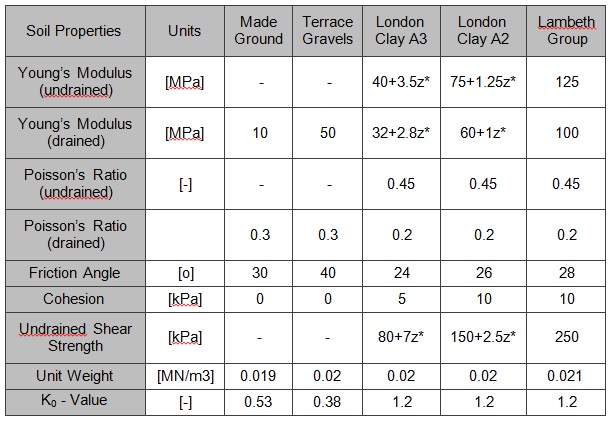
Table 1 – Geotechnical parameters as assumed in the tunnel design of the Bond Street Station Upgrade Project (note z*: depth from top of the LC stratum)
4 Case studies
4.1 London underground Bond Street Station Upgrade
Based on current usage level and traffic studies, London Underground needs to upgrade Bond Street station (BSSUP) in order to provide capacity increase, enhanced passenger flow, and access to the existing platform tunnels (i.e. Jubilee Line and Central Line) and the prospective Crossrail Station. To achieve this goal, a number of additional tunnels will be built and connected to the existing tube system including 2 access shafts, one lift shaft, 4 construction adits, 2 binocular cross passage tunnels, 4 large concourse and connection chambers, 3 underpass tunnels, 2 over-bridge tunnels cutting through existing platform tunnels, 2 niches for electrical and mechanical equipment and 4 inclined tunnels for escalator barrels and staircases. This challenging design makes BSSUP one of the most complex tunnelling projects in the UK. The total length of tunnels amounts to approximately 450 m with tunnel widths ranging from 4 m to 12 m. The project is of particular complexity, due to the fact that the new tunnels are developed through a dense web of existing tunnels but also within a quite congested area with several significant buildings in proximity. Therefore, very strict limitations apply on tunnelling induced deformations. By the end of 2012 the design of the primary and secondary linings has been carried out and delivered from a preliminarily to a detailed design in the framework of a design-built contract, where design was headed by the Atkins-Halcrow JV and construction is taken over by the Costain – Laing O’Rourke JV (CoLOR).
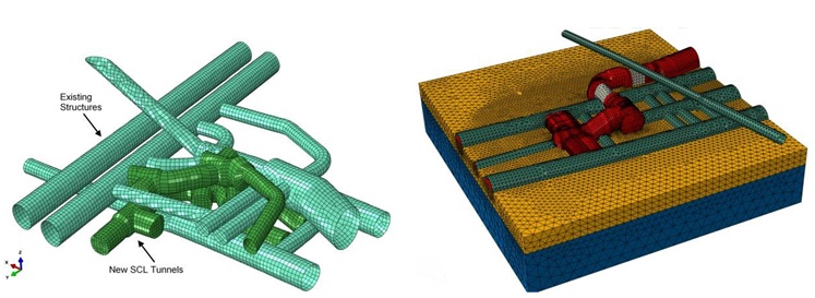
Figure 1 – FE-Modelling of existing tunnels and new SCL tunnels in the Bond Street Station Upgrade
In addition to a series of 2D analyses carried out in the preliminarily design, a comprehensive stepwise 3D analysis was inevitable due to the complexity of BSSUP. Due to the large extent of project, a single 3D-FE model including all tunnels was not feasible. Therefore 3 separate FE models were created as depicted in Figure 1, with approximately 600 000 to 1 000 000 elements each. Water table stands 6m below ground surface. The majority of the SCL tunnels are located within the London Clay stratum with a very low permeability. Therefore undrained soil parameters are considered for the analysis of tunnel excavation stages and the primary lining installation. The typical tunnel support in this project consists of primary and final linings comprising sprayed steel fibre reinforced concrete (SFRC). The primary lining is designed to carry temporary loads only and the final lining to sustain the long term loads including water pressure, assuming that the primary lining deteriorates in time and there is no load sharing between them.
4.2 London underground Tottenham Court Road Station Upgrade
Tottenham Court Road (TCR) Station in central London is upgraded to provide step-free access from the street level to all platforms and interchanges via the enlarged and new ticket halls; additional access points were designed to the Northern and Central Line platforms to (a) relieve congestion and (b) to provide connections to the TCR Crossrail Station. The winning tender for this design scheme was made by the joint venture (JV) of Taylor Woodrow and BAM Nuttall as contractors, and Halcrow with DSP in the design and site-supervision of the SCL structures with a total length of 380m.
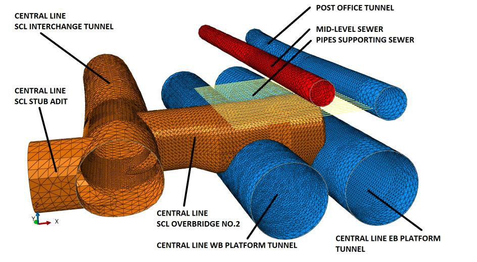
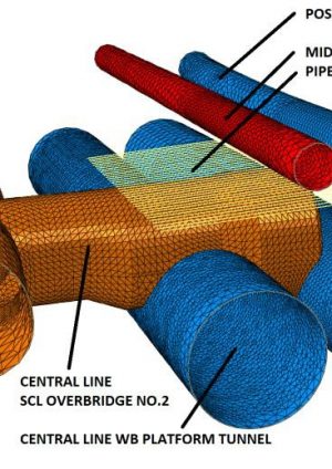
Figure 2 – 3D FE model of the Central line SCL overbridge at Tottenham Court Road Station including the existing and new structures
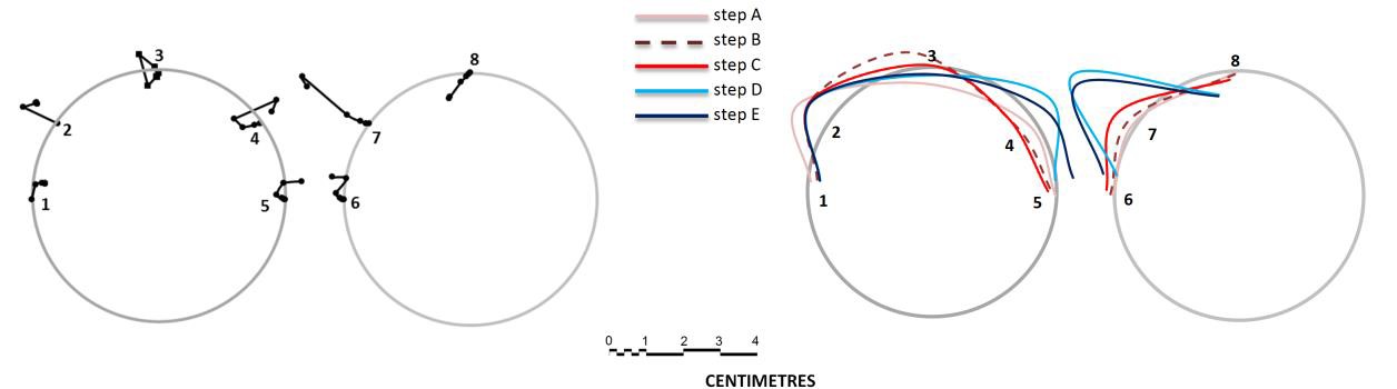
Figure 3 – Platform tunnel deformations at the over-bridge axis: monitoring data (left), and nonlinear 3D model predictions at various construction steps (right)
Tunnel diameters vary between 4.0m for cross passages and 11.0m for the Northern Line Concourse Tunnel. Multiple transitions and interfaces to existing LU structures sought a challenging design and construction scheme under the busy streets of central London. The initial SCL construction method and design of tunnels were changed after the contract was awarded replacing wire-mesh and lattice girders with SFRC. One of the most important additional changes was the replacement of the original timber-propping/square works design of two over-bridges (a cross passage passing over a platform tunnel with partial removal of the platform tunnel) with an SCL structure. This is the first time in the UK that over-bridges have been constructed in SCL. This change in the overbridge design provided a significant saving in cost and 7 weeks for the construction program, and was a highly successful value engineering exercise.
DSP performed a three dimensional finite element analysis to support the over-bridges design, as well as the impact assessment of the over-bridge on adjacent existing structures, i.e. central line platform tunnels, existing mid-level sewer and existing Post Office Tunnel (Figure 2). For the described layout, the ground was modelled using 740 000 linear tetrahedral elements and sprayed concrete linings were modelled using 40 000 linear shell elements, while undrained soil parameters were taken for the analysis in order to account for the “fast” construction in comparison with the time of consolidation in LC. Construction of the primary lining was completed in summer 2012 and the monitored displacements in the two platform tunnels showed a good conformity with the 3D model predictions as shown in Figure 3, not triggering any impact on the operation of the LU Central Line.
4.3 Crossrail Farringdon Station
Farringdon Station will be the only one among the 8 Crossrail interchange stations in London that provides access to all three rail networks of London (i.e. Crossrail, London Underground, and the National Rail) making it one of the busiest train hubs in the UK. This Crossrail station comprises 2 ticket halls, a lift shaft, passage connection to Thameslink, 2 Escalator barrels, 2 concourse tunnels, 11 cross passages, 2 ventilation adits and two 300 m long Platform Tunnels.
The Crossrail Farringdon Station is a deep level station with two platform tunnels stretching between the existing London Underground Farringdon and Barbican Stations at a depth of approximately 30 m below street level. The contractor, Bam-Ferrovial-Kier JV (BFK), was awarded the construction contract (C435) for the main construction works at Farringdon station by Crossrail Limited (CRL) in November 2011. SCL tunnels mainly drive through the border of LG and TS layers with overlying strata of LC, RT and MG formations. In addition, the tectonised region (4 normal and reverse faults perpendicular to the station) and sporadic confined sand lenses and channels – potentially with high water pressure – make ground conditions for tunnelling in this region rather challenging. DSP has been appointed by BFK to provide the design support for all the temporary SCL works such as depressurization, excavation sequences, or tool box items, within the Crossrail integrated design process. The station lies underneath buildings with poor structural conditions such as Lindsey Bridge.
3D non-linear FEA divided into 3 large models were employed to cover the whole SCL station structure, assessing the ground movements, face stability, structural design and excavation sequences. Figures 4 and 5 illustrate the models used for various parts of the station. Figure 6 indicates the agreement between predictions with non-linear FE models and the settlement monitoring data obtained during construction above a wraparound excavation (PL2RC) with a section area of 57 m2 at the west end of the station.
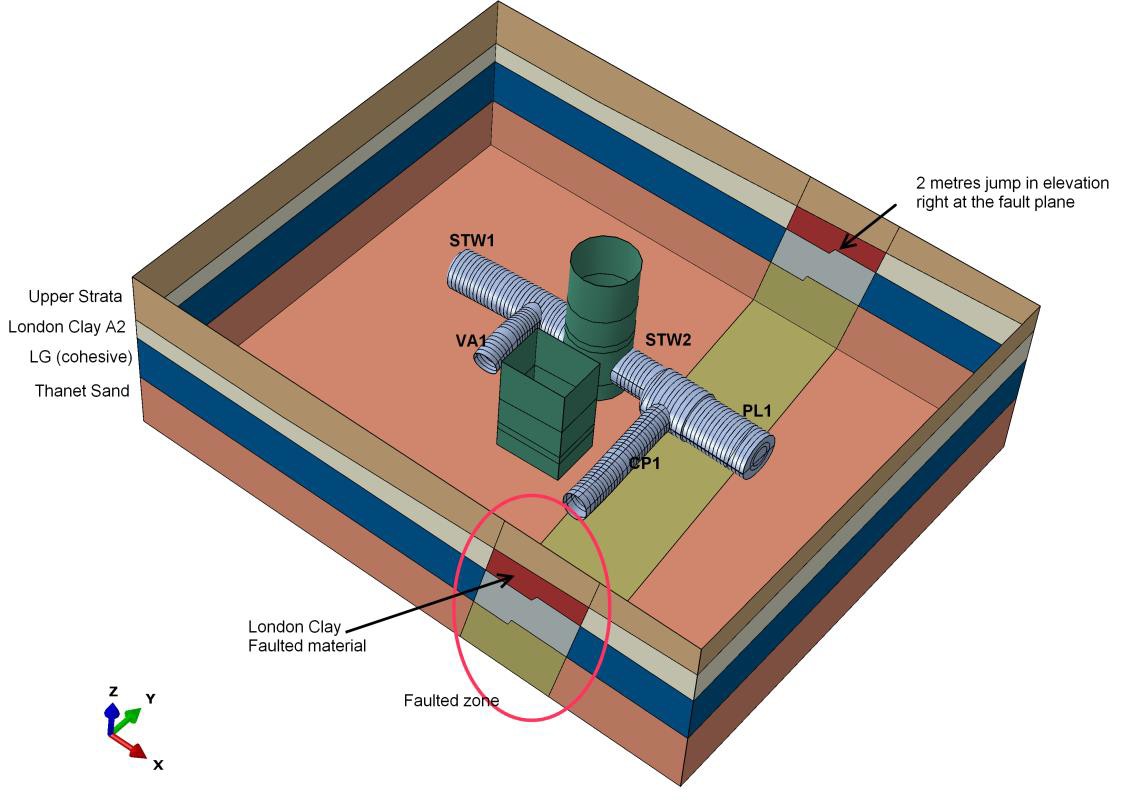
Figure 4 – 3D FE model overview of the Farringdon Station West Ticket Hall and the fault zone
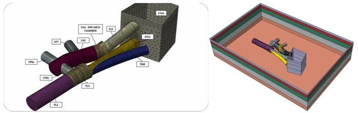
Figure 5 – Overview and detail of the 3D FE model for the Farringdon Station Eastern Entrance Ticket Hall
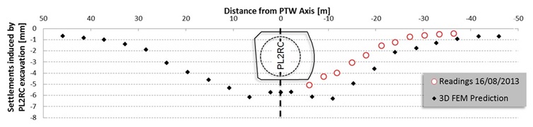
Figure 6 – Ground surface settlements induced solely by the PL2RC excavation against measurements on the surface.
4.4 Crossrail Limmo Auxiliary Shaft
The Limmo Auxiliary Shaft forms part of contract C305 awarded to the Dragados-Sisk JV covering the eastern section of the Crossrail running tunnels between Victoria Dock Portal to the Eastern end of Farringdon Station, and from Stepney Green Shaft to the Pudding Mill Lane Portal. These tunnel drives comprise approximately 11.95km of twin bored tunnels and a number of structures to be built using Sprayed Concrete Lining (SCL), for which DSP is providing design, supervision, and construction management services. The Limmo Auxiliary Shaft is a 27m internal free diameter and 37.8m deep structure intended to provide direct temporary access to the Crossrail tunnel alignment where four openings allow TBM drives to enter and exit the shaft. It has a top section of sheet-piling (to a depth of 17m, meeting the London Clay stratum) and a lower SCL section (another 24 m deep) leading to the SCL Launch adits and backshunt stub tunnels, which had been the focus of the design. This structure was decided on an alternative of the twin shafts originally envisaged at this very location in the final design in order to facilitate the increased flexibility for the Drives Y/G construction and the assembly of the TBMs, to optimise the SCL works and early TBM launch, and finally to decrease the programme risk for the TBM works.
The design of the SCL shaft and the impact assessment on adjacent existing structures were based on a three dimensional finite element analysis. Critical existing structures included the Limmo Main shaft and the Docklands Light-Railway (DLR) both at a distance of approximately two diameters, and the existing gas main at a distance of roughly 20 m from the excavation. The ground was modelled using 75000 second-order tetrahedral elements and sprayed concrete linings were modelled using 11000 second-order triangular shell elements (Figure 7). The model proved to have yielded a good prediction of the breakouts’ structural behaviour and combined with an engineered monitoring and action-trigger scheme it provided an optimum structural assessment and design illustrated in Figure 8.
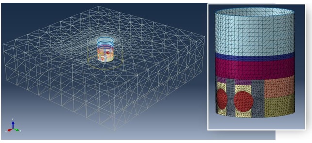
Figure 7 – Overview of the 3D FE model for Limmo Shaft.
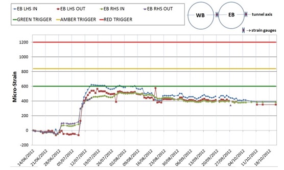
Figure 8 – Limmo Auxiliary Shaft – Rebar strain measurement at axis level of Eastbound tunnel / West. (Note: Green trigger is the unfactored value predicted in the FE analysis)
4.5 Independent design check of Crossrail Category 3 SCL structures
All SCL structures of Crossrail are Category 3 structures in the UK and Eurocode classification system and as such they represent infrastructure with the highest risk elements meaning that the highest level of checking effort needs to be undertaken. The independent design check in this case is a fully independent calculation of the structural lining, a thorough review of the proposed construction procedures (excavation sequence) and a review of material and workmanship specifications. This procedure leads to a substantial refinement and increased confidence for the design. On Crossrail, all SCL design has been performed under the contract C121 in the period 2009-2011. The designs to be certified with a Category 3 Independent Design Check (hereafter C3IDC) were the final design packages and the temporary works, as well as changes performed in later stages including the contractor driven amendments (the Limmo Auxiliary Shaft is an example). For the C3IDC for SCL structures in Crossrail Mott-MacDonald assigned URS (then Scott Wilson) the role of the C3IDC checker. URS assembled a team of SCL specialist sub-consultants such as IGT, Donaldson Associates, and DSP to check individual structures, and iC Consultants to provide high-level technical reviewing services, with DSP carrying out the design check of the Whitechapel Station and Crossover, the Fisher Street Intervention-Ventilation Shaft and Crossover, and two wraparound structures in Bond Street Station. The work package also included structural calculations as a basis for the check of typical Bond Street Station and Liverpool Street Station junctions. A substantial part of the design check was structural checks of both the primary and the secondary support performed at critical parts of the above mentioned structures. The analyses where typically based on 2D staged models, while 3D modelling was implemented for the design check of specific components, i.e. breakouts/openings and tunnel junctions or wraparounds with wished-in-place modelling approaches. Also an advanced 2D analysis has been performed on a binocular construction. Indicative models are illustrated in Figure 9. Based on these efforts, a series of safety, structural, and logistic issues where identified and improvements took effect after recommendations of the design checker and in collaboration with the designer and occasionally the contractors.
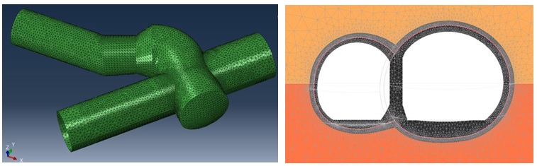
Figure 9 – Models for the Independent design check of Crossrail Category 3 SCL structures: 3D FE model of Wraparound detail (left) and 2D model of asymmetrical binocular tunnel (right)
5 Conclusions
Not more than a decade ago it was very difficult for designers to undertake massive 3D FE models and justify such analyses to clients in terms of time and cost for none-research projects. However, seemingly large 3D FE models are becoming a standard design tool in complex tunnelling projects like those demonstrated in this paper. In all projects discussed, 3D models were prepared with a reasonable time in the design period successfully. Valuable results were extracted from comprehensive 3D models that cannot be provided by 2D analysis which has inherent subjective assumptions. In fact providing 3D models which enable us to explain complex ground behaviour helped us to prove the value engineering ideas and push forward the design approval process with more confidence and make novel ideas happen. Finally, it shouldn’t be forgotten to allocate reasonable time and cost for performing 3D analysis in a design programme, and it ought to be undertaken by experts who fully understand tunnelling, Geotechnics and Finite Element principles.
References
Crossrail Ltd. 2009 – Crossrail Context Report. London
Crossrail Ltd. 2009 – Geotechnical Sectional Interpretative Report 1&2: Royal Oak to Liverpool Street
Dassault Systemes Simulia: ABAQUS Analysis User’s Manual-V6.12, 2011
Feiersinger, A. 2011. Comparison of deformations predicted using 3D finite element analysis with deformations encountered during construction. Tunnels and Tunneling. August 2011: 53-56
Feiersinger, A. & Mitsch, T. 2010. Deformation comparison at Green Park. Tunneling Journal. December 2010 – January 2011: 24-29
Feiersinger, A; Mitsch, T.; Spyridis, P. (2012): Preservation of structural and functional integrity in the in teraction of new and existing structures: the case of London Underground´s Green Park station. In: The third International Symposium on Life-Cycle Civil Engineering – IALCCE 2012 Vienna 3-6- 1 Oct. 2012.
Final Geotechnical Interpretative Report (GIR) 2009 – Bond Street Station Upgrade Project
Firth, A. Adding confidence and reducing risk – the role of independent design checking in major projects. IABSE Symposium, Weimar 2007, International Association for Bridge and Structural Engineering
Gakis, A., Flynn, S., & Nasekhian, A. (2014). Back Analysis of Observed Measurements for Optimised SCL Tunnel Design. North American Tunneling: 2014 Proceedings.
Gakis, A., Salak P. StJohn A. Geotechnical Risk Management for Sprayed Concrete Lining Tunnels in Farringdon Crossrail Station In: World Tunnel Congress 2014. Iguassu Falls – Brazil, May 9-15, 2014.
Spyridis, P., Nasekhian, A. and Skalla, G. (2013), Design of SCL structures in London / Entwurf von Tunnelbauwerken in Spritzbeton-Bauweise am Beispiel London. Geomechanics and Tunnelling, 6: 66–80.
-
Authors

Ali Nasekhian, Dr-Ing - Dr Sauer & Partners Ltd
FE Design Engineer, Crossrail Farringdon Station
Angelos Gakis Dr. Dipl-Ing, MSc DIC, CEng MICE - Dr Sauer & Partners Ltd
Chief Geotechnical Engineer, Crossrail Farringdon Station
P Spyridis
Dr. Sauer & Partners
Thomas Schwind BSc - Dr Sauer & Partners Ltd
Technical Director, Dr. Sauer & Partners
