Connaught Tunnel Surface Rail Approaches Settlement Mitigation
Document
type: Technical Paper
Author:
Jane Hughes BSc, CEng, MICE, Jonathan Craft BSc, MSc(Eng), DIC, CEng, MICE, ICE Publishing
Publication
Date: 07/09/2015
-
Read the full document
Keywords
Geotechnical engineering; foundations; field testing & monitoring
List of abbreviations / notation
CRL Crossrail Ltd
DLR Docklands Light Railway
LUL London Underground Limited
ATD above tunnel datum
LM load model
CMC controlled modulus column
LTP load transfer platform
VCC vibro-concrete column
CFA continuous flight auger
1. Introduction
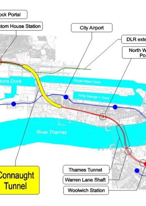
The London Docklands section of the Crossrail railway line which runs between Custom House Station and North Woolwich Portal, passes beneath the Royal Docks through the rehabilitated Connaught Tunnel (ref. Figure 1). The Crossrail Act of 2008 incorporated the tunnel and its approaches into the south-east branch of the new Crossrail line between Whitechapel Station and Abbey Wood which is due to open to the public in 2018. While the new track either side of the approaches to the existing tunnel, is at grade and follows the alignment of the defunct North London Line, a ballasted track was deemed unsustainable given the requirement for frequent interventions and track tamping to maintain its functionality throughout the mandated 120 year design life. Furthermore, given that the rest of this section of Crossrail is on slab track, it would have been an impracticable proposition to mobilise the essential tamping equipment for such a relatively short stretch of track. Therefore, an alternative track support system was proposed here comprising a granular load transfer platform (“LTP”) bedded on a grid of vibro-concrete columns (“VCC”), and it is the design of this track slab foundation that is the subject of this paper.
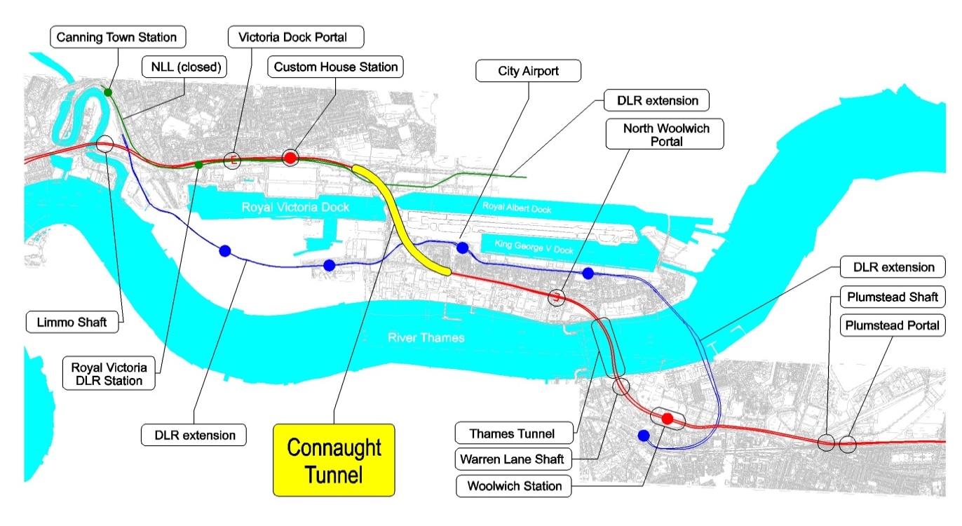
Figure 1 – Crossrail South-East Spur and Location of the Connaught Tunnel
2. Ground Conditions
Given that this is an existing albeit disused rail route, there is a variable thickness of Made Ground including track ballast immediately below grade especially along the surface (i.e. above-ground) sections of the route. Beneath the Made Ground there are layers of Alluvium and Peat overlying the sands and gravels of the River Terrace Deposits (“RTD”). This is common to all parts. However, the geology exhibits distinct differences either side of the Dock Passage. Thus, to the north (and west) of the Dock passage a wedge of London Clay is encountered between the RTD and the Lambeth Group, while to the south (and east) the RTD sit directly on the Thanet Sand. In other words the Lambeth Group thins out beneath the Dock Passage.
Measured groundwater levels in the Upper Aquifer ( RTD) are between 97 m ATD and 100 m ATD (approx).The tunnels would appear to have been founded on very stiff clayey horizons within the Lambeth Group. Underlying the Lambeth Group is found the Lower Aquifer comprising the Thanet Sands and Chalk. Piezometric levels in the Lower Aquifer are between 85 m ATD and 88 m ATD.
The geology of the east and west Surface Railway sections is summarised in Tables 1 & 2 and illustrated in Figure 2.
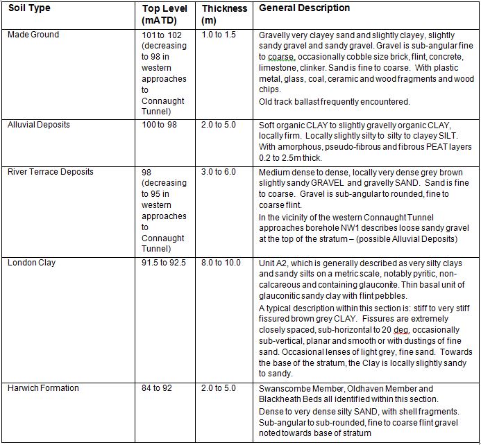
Table 1 – Geology beneath the Connaught Tunnel Western Surface Railway (based on borehole information)
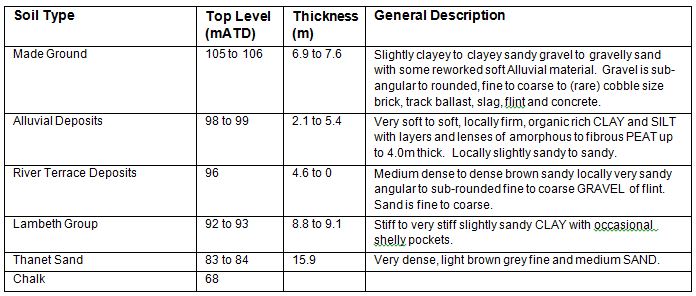
Table 2 – Geology beneath the Connaught Tunnel Eastern Surface Railway (based on borehole information)
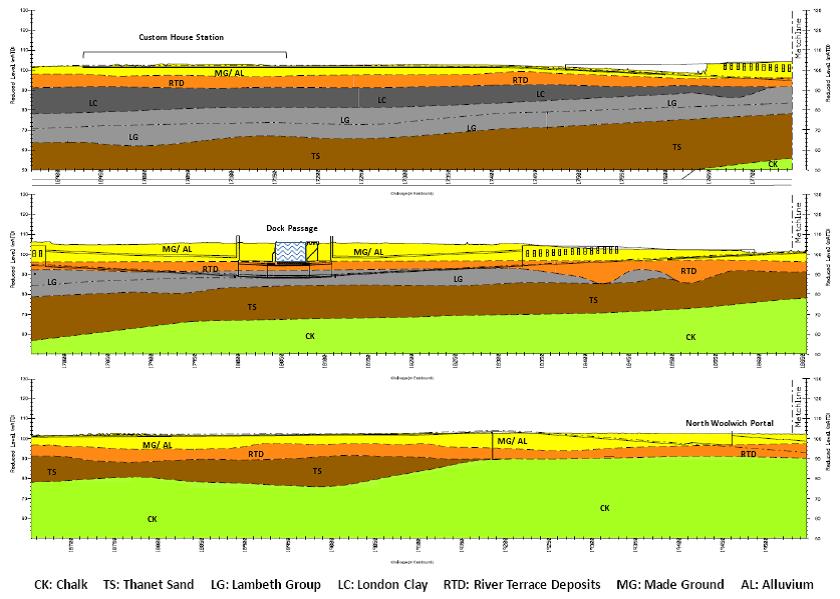
Figure 2 – Geology of Connaught Tunnel and Approaches
3. Design
3.1 Performance Criteria
Design loadings are based on the requirements of BS EN 1991-2:2003.
Thus,
- vertical loading is based on LM 71 as indicated here below, and
- traction loading is 825 kN over 25 m length on each track (SLS unfactored).
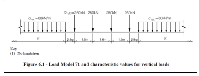
It is considered that the application of the 250 kN wheel loads represents an exceptional load case as it is very unlikely to endure for appreciable lengths of time when compared to the design life of the railway. In other words, based on LM 71, at any moment in time under a 200 m long train, point loads totalling 1000 kN are applied over a length of 6.4 m while 80 kN/m run is applied over the remaining 193.6 m of the train as it moves along the track. It is considered reasonably conservative therefore, when modelling this as a two-dimensional loading case to average this loading to 82.4 kN per linear metre of track.
3.2 Settlement Mitigation
When calculating immediate (‘construction’) settlements, a degree of engineering judgement is required regarding the proportion of settlement that is likely to occur under undrained and drained conditions. In this case, up to 6 years could elapse between the construction of the track-supporting slab and the first occurrence of live rail traffic, which is the baseline for the measurement of ‘additional’ settlement due to live loading. Thus in calculating construction settlements, it would be reasonable to include a proportion of long-term (i.e. drained) settlement due to consolidation of the clay layers beneath the toes of the ground improvement columns under the dead loading only during the period before the railway becomes operational.
Under live rail traffic, due to the repeated rather than sustained loadings, the soil will be subjected to cycles of undrained-drained behaviours. Thus it could be argued, that more realistic estimates of settlement could be obtained by adopting soil stiffnesses in the analysis that lie between drained and undrained values. However, the total settlement calculations carried out in this study have been based on the use of drained stiffnesses for the live loadings, and may be deemed therefore to represent a worst case scenario.
4. Ground Improvement Scheme
The requirement for frequent interventions and track tamping to maintain a ballasted track was deemed unsustainable to support the above loadings over the 120 year design life required by Crossrail for their railway. Therefore, an alternative track support system has been designed. This comprises a granular load transfer platform (“LTP”) bedded on to a 1800 mm triangular grid of 450 mm diameter VCC installed through the alluvial deposits down to the RTD on a. Soil parameter values adopted in the calculation of settlement for the ground improvement scheme are given in Tables 3 and 4 below. These are considered to represent the worst case where the maximum thickness of Alluvial Deposits and minimum thickness of RTD are found.
The stiffnesses of the Alluvial Clay and the Peat have been derived from oedometer test results (see Table 3 below).
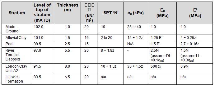
Table 3 – Soil profile and parameter values for settlement assessment of ground improvement design: Custom House to Connaught Tunnel (Note: z is depth measured from ground level)
The following data was used for analysis of the surface railway between Connaught Tunnel east approach and North Woolwich Portal to characterise the worst combinations of peat and soft alluvial clays:
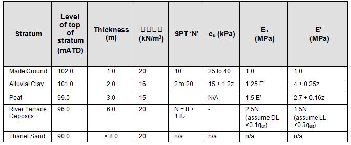
Table 4 – Soil profile and parameter values for settlement assessment of ground improvement design: Connaught Tunnel to North Woolwich Portal (Note: z is depth measured from ground level)
In the event however, the Contractor proposed an equally effective but more economical alternative solution comprising six rows of 320 mm diameter (nominal) so-called Controlled Modulus Columns (“CMC”) on a square grid generally at 1.8 m centres and toed a minimum of 1.0 m into the RTD. The columns have a single, full length reinforcing bar plunged into the wet concrete and are trimmed flush with the LTP. A layer of woven geotextile is placed on top of the CMCs to prevent the LTP material from punching through into the underlying soils (usually soft to firm alluvial deposits).Type 6N engineering fill is then placed and compacted in layers to achieve a minimum stiffness (E) of 50 MPa.The resulting 450mm thick load transfer platform (see Figures 3a & 3b) acts as a stiff transfer medium designed to distribute the imposed track loads to the CMC reinforced ground and the underlying more competent River Terrace Deposits.
The design was carried out using a combination of 2-D and 3-D finite element (PLAXIS) analyses, based on input data derived from the parameters given in Tables 3 & 4 above.
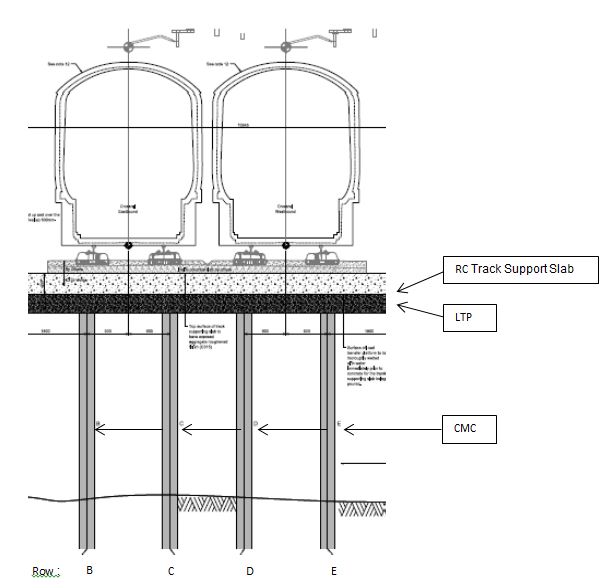
Figure 3a – Typical surface rail track foundation cross-section
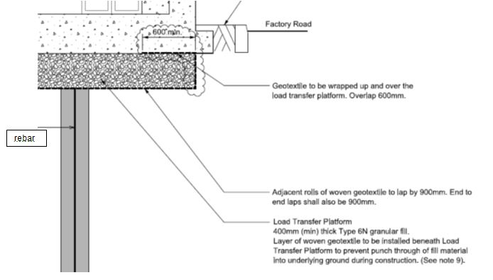
Figure 3b – Typical surface rail track foundation – detail
5. Controlled Modulus Columns
Both the as-designed scheme of ground improvement (VCCs on a triangular 1800 mm grid) and the Contractor’s alternative, are based on displacement piling methods, which a priori would tend to cause heave in the alluvial clays and silts overlying the River Terrace Gravels. However, the extent of such heave was very much mitigated by the adoption of the scheme as constructed, as the CMCs, being of smaller diameter and on a coarser grid (1800 mm square), displace approximately 80% less ground than the original scheme based on VCCs.
The CMC system comprises a hollow stem mandrel mounted on a high torque powerful pull-down piling rig similar to a CFA rig[1]. The displacement auger is composed of three different sections:
- the bottom part has a constant-volume flight which evacuates the arisings upward during penetration;
- the middle part has the same diameter as the auger thereby not only inhibiting evacuation of the arisings but pushes them laterally displacing the surrounding ground;
- the upper part is a regular auger but with flights in the opposing sense to the bottom part thereby bringing any remaining disturbed ground down to the displacement section and so improving the overall quality and continuity of the column.
This is essentially a vibrationless process (i.e. unlike the originally proposed VCC technique). Once the desired penetration into the RTD (a minimum of 1.0m) has been achieved which is indicated by a large increase in torque as captured by the on-board computer and as displayed on the screen in the driller’s cab, drilling is stopped. Concrete is then pumped into the hollow stem of the mandrel as the latter is extracted, always ensuring that at all times there is a positive head of concrete at the base of the mandrel to prevent the occurrence of necking of the column due to suction.
The design of a grid of CMC is based on the optimum distribution of loads between the columns via the load transfer platform and the surrounding ground. However, whereas a scheme based on stone columns may be said to improve the host soil by enhancing its overall deformation modulus – there being a relatively small difference in the respective stiffnesses of soil and column (say between 1/10 and 1/100) – substituting CMCs for stone columns increases the comparable stiffness ratio by three or four orders of magnitude. In this case, an equal plane strain hypothesis is no longer applicable. Rather, analysis indicates that the ground just beneath the LTP tends to settle more than the column (i.e. the column head is tending to punch into the LTP) whereas at the toe the column settles more than the ground (i.e. column toe is penetrating into the competent ground beneath). In other words, while negative skin friction is occurring at the upper levels leading to higher compressive stress concentrations in the top section of the columns, there is a neutral point in the column below which the column is subject to positive skin friction whereby the load is transferred from the column to the ground. Such complex load-transfer behaviours in the soil, can only be modelled in a meaningful way by using finite element or finite difference analyses. The use of such programs allows variable geometries and ground conditions to be taken into account as well as asymmetric rail loading conditions and train braking forces.
6. Preliminary Load Testing
6.1 Zone Tests
Preliminary testing comprised a combination of individual column and zone testing. The methodology for the zone testing is outlined in the ICE Specification for Ground Treatment, 1987[2]. After the installation of the CMCs and trimming thereof to the required cut-off level, geotextile was laid across the test area and a 400mm thick layer of compacted Engineering Fill (Type 6N) was placed. A grillage of steel beams was set on this fill to form a square loading platform 3.6m by 3.6m. The zone was loaded incrementally up to the specified working load (WL) of 30kN/m2 (equivalent to 389kN over the zone), then to 150% WL and finally to 250% WL, sustaining this load before unloading to zero.
Examples of the resulting load-settlement curves are shown in Figures 4 & 5.
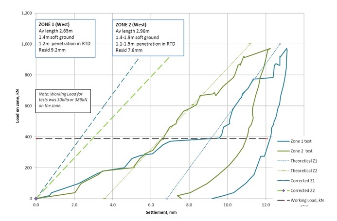
Figure 4 – Zone test load-settlement chart on CMC groups – West
For each preliminary zone test, the maximum displacement (averaged over the four monitored points) has been plotted against load and is presented in Figures 4 and 5. Ignoring early bedding-in effects, a theoretical line has been drawn to give a ‘corrected’ load-settlement line. It can be seen that the gradient of the corrected lines, which can be correlated with the soil stiffness, is very similar for all cases.
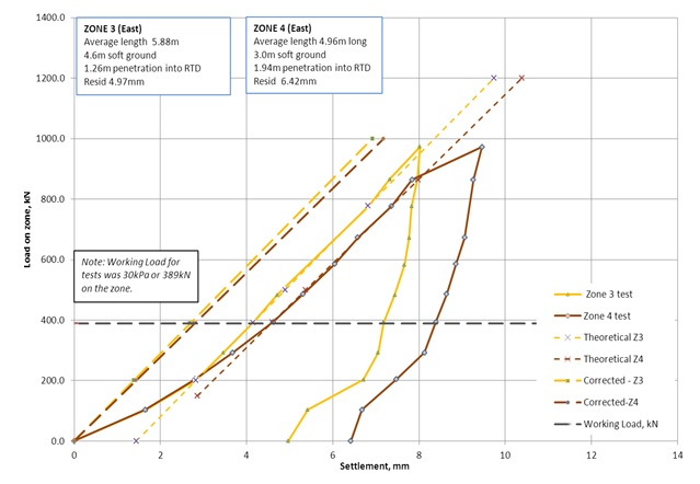
Figure 5 – Zone test load-settlement chart on CMC groups – East
Using simple elastic methods, approximate drained stiffnesses (E) have been derived for the River Terrace Deposits adopting this corrected load-settlement relationship from the Zone Tests. These are presented in Table 5 below. The E values that were agreed in the Approval in Principle document[3] and input to Plaxis analyses for specific locations are also included as a comparison
Zone Test and approximate chainage E’, MN/m2of River Terrace Deposits derived from Zone Tests E’, MN/m2,of River Terrace Deposits, assumed in Plaxis analyses CMC toe Base of RTD CMC toe Base of RTD Zone 1 and 2 (West)
E/B Ch 17500
33 52 – – West: E/B Ch 17270 – – 37 57 West: E/B Ch 17460 Constant 50 Zone 3 and 4 (East) E/B Ch 18750 and 19010 30 53 E/B Ch 18950 31 55 E/B Ch 19175 38 56 Table 5 – Soil-stiffnesses comparison
The stiffnesses assumed for design purposes are very close to those derived from the site zone tests and it was therefore concluded that the parameter values adopted for the design were valid.
6.2 Individual CMC Tests
The plate load tests indicate the typical load carrying characteristics of the CMCs in end bearing, in contrast to the zone tests which reflect the overall behaviour of the ‘improved ground’. Thus the plate load test results provide further assurance of the integrity and competence of the individual element and the stratum in which it is founded.
It can be seen from the straight line portions of the plots in Figures 6 and 7 that CMCs which are constructed to Specification are generally capable of operating within their elastic range up to loads of at least 200kN.
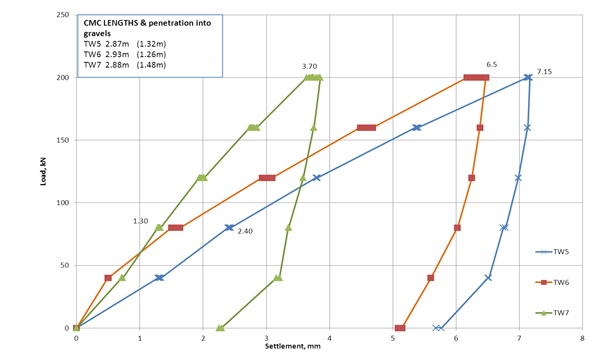
Figure 6 – Load-settlement chart for individual CMCs – West
TW7 gave a slightly stiffer response than the other two columns in the West, with a settlement of only 3.7mm under 250% WL compared with about 7mm for TW5 and TW6.
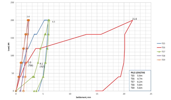
Figure 7 – Load-settlement chart for individual CMCs – East
The atypical behaviour of TE6 was attributed to construction defects and not ground conditions.
Elastic calculations based on the plate load test settlements indicate a short term stiffness in the River Terrace Deposits of about 77MPa at CMC toe level, increasing to about 90MPa at the base of the RTD. This is considerably higher than that assumed for design and confirms the competence of the soils at founding level.
7. Performance
Apart from the load testing as herein described, routine integrity testing, carried out on the heads of exposed CMC piles prior to the placement of the LTP, demonstrated the acceptability of each column as installed.
Long term monitoring will assure the overall performance of the system under live loading, in preparation for which, baseline co-ordinates will have been recorded at regular intervals along the alignment after the construction phase has been substantially completed.
8. Conclusions
The studies and testing carried out on this site have demonstrated that the Contractor-proposed alternative track slab foundation based on a grid of controlled modulus columns, is not only a cost-effective means of mitigating settlements on this site, but it offered the project significant cost and programme savings. It also had environmental benefits in that the already low volume of spoil that would have been generated had the VCC (also a displacement piling technique) been used, was further considerably reduced due to the substitution of the CMC technique, hence leading to even fewer tipper lorry movements to and from the site. Furthermore, the CMC process required less energy than the VCC process which combined with the programme savings referred to above, meant that the overall carbon footprint of this phase of the works was significantly reduced. In addition, because the CMC installation does not require any vibratory energy, it was also a lot quieter process than VCC installation, thereby minimising its impact on the neighbourhood.
References
[1] F Masse, B Brockbank & S Pearlman (2004) CMC (Controlled Modulus Columns): Potential Application to Canadian Soils with a New Trend in Ground Improvement. Geo-Quebec 2004: 57th Canadian Geotechnical Conference, Session 4F pp 32-39
[2] Institution of Civil Engineers (1987) Specification for Ground Treatment, pp 13-17
[3] J Hughes (2011) Approval in Principle for Ground Improvement Works between Custom House Station and North Woolwich Portal. Crossrail Limited Document No.: C122-OVE-C2-RGN-CR146-50001
-
Authors

