Covered Way 126 – Safeguarding a Brittle Structure over a Live Railway during Ground Movements
Document
type: Technical Paper
Author:
Richard Bailey, Mark Steele, Paul Braddish, ICE Publishing
Publication
Date: 31/08/2016
-
Read the full document
Introduction
The Crossrail project includes a new railway under London, with 21km of new twin running tunnels and major new station works at 10 locations. At Whitechapel new facilities for Crossrail form an expansion of the existing station which serves London Overground and Underground lines. The C122 Arup-Atkins joint venture was employed by Crossrail to assess the effects on existing buildings and infrastructure of the ground movements arising from underground Crossrail works, and where appropriate to devise means of mitigating these effects.
This paper describes the assessment of Covered Way 126 (CW126) at Whitechapel, and the design and implementation of mitigation measures which safeguarded the Victorian tunnel structure against damage resulting from ground movements induced by Crossrail.
Context
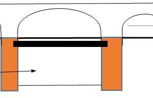
CW126 is situated to the north-west of Whitechapel Station. It is a cut-and-cover tunnel structure which encloses two tracks of the London Overground (LO) railway. It consists of masonry abutment walls supporting cast-iron roof girders, which in turn support masonry jack arches. The cast-iron girders in the tunnel roof structure are solidly built into the abutment walls, and are constrained from rotating in the event of differential settlement between the walls. The girders span over live tracks and hence the implications of damage due to ground movement were potentially severe.
Figure 1 shows the new Crossrail works and existing railway assets at Whitechapel. The Durward St. shaft, the eastbound running tunnel, and the bypass tunnel are the works which were assessed to cause most of the ground movement at CW126.
The crowns of the new running and station tunnels are about 20m below ground level. The external diameters of the bored running tunnels and platform tunnels are 6.8m and approximately 11m respectively. The station tunnels, and the tunnels near CW126, were constructed using sprayed concrete. Most of the running tunnels were constructed using tunnel boring machines. Vertical circulation is achieved in the 30m deep Durward St shaft, which was formed with diaphragm walls and a bottom-up construction sequence. New works at ground level will transform access to the station and interchange between lines.
The covered way runs along an approximate NNW-SSE axis. For simplicity, in the remainder of this paper the covered way is taken as running north-south, and the girders east-west.
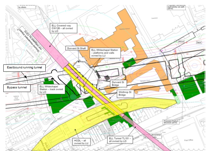
Figure 1 – Station layout at Whitechapel © Crown Copyright Brief history of CW 126
The East London Line (ELL) at Whitechapel was opened in 1876. Between 1933 and 2007 the line was operated by London Underground.
The structure which became CW 126 originally had three levels: the 3 tracks of ELL ran between 5 and 7m below ground level; at ground level a jack arch deck supported on cast-iron beams carried access roads, while a brickwork arched viaduct carried six sidings of the Spitalfields Coal Depot over the top at a 50° skew, all as illustrated in Figure 2.
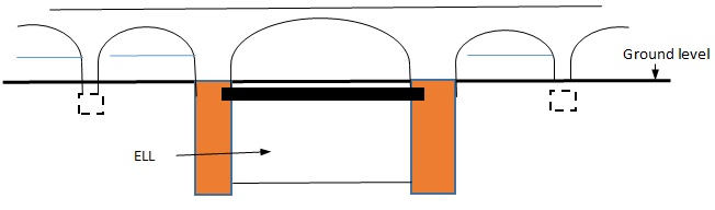
Figure 2 – Earlier form of structure which became CW126 The main span over the East London Line appears to have been a skew arch. The adjacent arches were all square. The transition from skew to square arches required piers of irregular thickness.
Circa the late 1960s the arches above ground level were demolished, leaving a structure similar to that which exists today. The remaining abutments below the old arches, which form part of the walls of CW126 have a variable thickness, and are significantly thicker than required for the structure which remains.
In December 2007 the ELL was closed for extensive improvement works as part of the East London Line project (ELLP), and reopened as part of LO in April 2010. Reference 1 gives an overview of the project. The improvement works at Whitechapel included various measures in preparation for Crossrail, and modifications to CW126. The latter consisted of:
- Reducing ground level above the roof of the covered way by removing a thickness of fill.
- Reducing the height of the parapets on the end girders.
- Casting a 100mm thick fibre reinforced concrete slab over the old roof and using it as a substrate for a new waterproofing membrane.
- Installing tie-rods between the bottom flanges of each end girder and the adjacent internal girder.
- Taking cores through the abutments walls, several of which proved the thickness of the abutments to be between 3 and 4m.
During the CRL works site offices and a storage deck were supported off steel beams which spanned east-west between concrete bases founded on the two abutments of CW126. Although these were relevant to the assessments and the design and implementation of mitigation works, the effects were secondary, and for conciseness these aspects are not considered further in this paper.
The situation prior to Crossrail
The layout of CW126 and its surroundings immediately prior to commencement of the Crossrail project are shown in Figure 3. The girders at the south end of the covered way are shown in Figure 4.
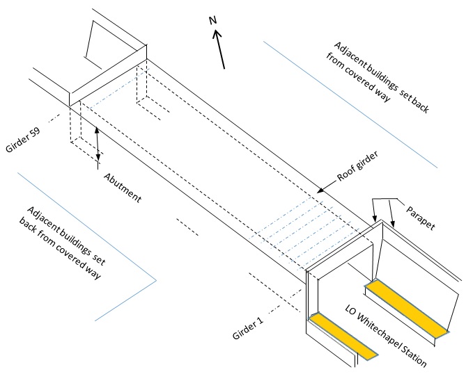
Figure 3 – CW126 and its immediate surroundings The clear separation between the below-ground abutment walls is a nearly constant 11.5m.
The cast iron girders have 610mm wide bottom flanges and support jack arches with a span of 915mm. The end cast-iron girders supporting high parapet walls and are 915mm deep I sections. The remaining girders are hog-backed with height varying from 610 to 915mm and with 102 mm wide top flanges. In total there are 59 girders, giving an overall length for the covered way of 89m. Note that all dimensions given in this paragraph are approximate.
Ground investigations commissioned by Crossrail indicated that the abutments were founded a little into the London clay, with the superficial material being River Terrace Deposits, alluvium and made ground. A small amount of perched ground water was found at top of the London clay.
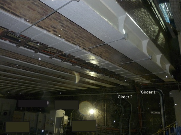
Figure 4 – Girders at south end of CW126 Assessment for existing loads
In order to determine the residual allowable stresses in the girders which could be mobilised to resist settlement effects, the girders were initially assessed using the allowable stresses given in BD21/014 under existing dead loading. The assessment was based on simply supported end conditions, which were likely to have existed when the dead load was originally applied to the girders. The BD adds support to this assumption by specifying that composite action with the jack arches is not taken into account for dead loads.
Each end girder carries only half a jack arch span but also supports a high brickwork parapet (reduced in height during the ELLP). The end girders have top flanges as wide as their bottom flanges, and are as deep at midspan as the internal girders. It was shown that under vertical loads only the internal girders were the critical case.
Unsurprisingly, the limiting factor was the tensile stress in the bottom flanges at midspan. Away from the southern end of the covered way, the tensile stress due to existing loads was approximately 70% of the allowable, leaving a residual of 13N/mm2 to resist load effects from ground movement.
Included in the analysis of the girders near the end of the covered way was an assessment of the stresses which arise from unbalanced lateral reactions from the jack arches at the end of the covered way. Tie-rods were installed between the end girder and the adjacent internal girder during the ELLP. It was not clear whether the rods had been tensioned to reduce the lateral reaction due to dead load, or whether they were intended to reduce the lateral stresses from imposed loads only. Various ways in which the structure might be carrying these reactions were considered and a reasonable estimate of the resulting stresses was made. The residual stress available to carry ground movement effects was less than that distant from the ends of the covered way, and less certain.
Assessment for ground movement
Ground movements were calculated for each part of the Crossrail underground works and summed to get the combined effect on CW126 at different stages of construction. The principal aspects of movement were:
- Settlements localised at and increasing towards the south end of the structure
- settlements greater on the west side than on the east
- lateral movements and slope of the ground tending to force the top of the east abutment eastwards (and no such effect at the west abutment)
The effects of distortion on the abutments in their own planes were assessed using the method proposed by Burland2 and shown to be small. It was shown that after discounting a rigid body rotation the remaining distortion of each jack arch was a negligible twisting.
A first step in assessing the girders for the effects of ground movement was to understand the detail where the girders take support from the abutments. Investigations during the ELLP had shown that the embedment length was about 600mm. The girders are built into the brickwork of the abutments. Such details are conventionally taken as simple support in assessing for vertical load. However this may be a simplification which is conservative in assessing for vertical load but unconservative in assessing for ground movement.
Previous experience within Arup of load testing masonry jack arch floors on cast iron beams in late Victorian mill buildings was taken into consideration when determining the implications of girder end fixity and load application on girder stresses. It was noted that these floors often display the following characteristics:
- Girder end fixity and continuity across internal supports through composite action between the cast iron and the masonry, achieved through the ability of lime mortar to form a strong bond to the cast iron and to resist tensile stress.
- Load sharing to adjacent girders.
- Cross-vaulting, causing a proportion of the imposed loading to be taken through the masonry directly to the stiffer support points, bypassing the girders.
By comparison with information in reference 3, the abutments of the covered way are thicker than would be needed for a gravity wall of the same retained height. The normal assumption that the roof of the covered way must be in compression in order to prop the walls apart was therefore not valid. The calculated movements of the abutments were such as to tend to put tension into the girders.
The amount of that tension could have been calculated using a soil structure interaction model. However it was possible to find an upper bound tension using a simple limit equilibrium model, as illustrated in Figure 5.
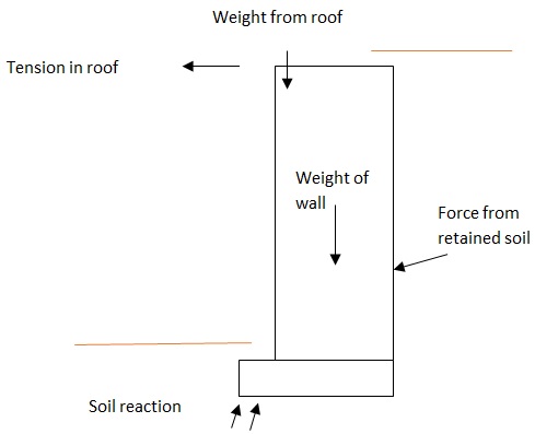
Figure 5 – Limiting equilibrium of abutment The calculation required an estimate of a lower bound pressure from the retained soil, and an upper bound bearing capacity of the soil under the base. The calculation showed that for a simple 2-dimensional arrangement the tensile stress induced in the girders could not exceed 2 N/mm2.
Beyond the southern end of the covered way the ground is retained by massive brickwork gravity walls. These are integral with the abutments of the covered way. The ground movements tended to pull the tops of these walls apart too. This suggested a potential to concentrate significant (but very difficult to calculate) tension in the girders at the south end of the CW. The girder tension could not exceed that which could be transmitted between the brickwork and the iron, but calculations showed that that amount could be significant. It was thought likely that the stiffness of the girders would tend to reduce the adverse movements, and that any tension in the girders would be small, but for the end girders this could not be proven.
A worst case calculation for differential settlement was carried out assuming that the girders were fully built into the abutments, and that the girders acted compositely with some of the material surrounding them. A simple calculation was done for the maximum moment that could be transmitted from the brickwork to a girder by shear on an enclosing perimeter, and by shear and tension within the brickwork on enclosing surfaces. In order to be cautious the calculation used upper bound brickwork strengths, which were derived from codified (lower) characteristic values using experience. It is usually cautious to ignore the tensile strength of brickwork, but in this case it was cautious to include it. Both of these calculations showed that the hogging bending tension in the asymmetrical standard internal girders arising from differential settlement could exceed the allowable stress.
Girder 1 is symmetrical and has parallel flanges and is thus much stronger in hogging near its supports than the standard girders. However the 2m high parapet which was continuous over the ends of girder 1, added to the restraint and it could not readily be shown that this girder would remain in a satisfactory condition either.
To test some of the assumptions in these calculations the brickwork around the end of one of the standard girders was removed by careful coring and chiselling. This revealed that:
- the girder had a trapezoidal end stiffener matching the widths of the two flanges
- the brickwork was strongly bonded to the iron wherever they met
- the brickwork was sound
- the bottom flange had slotted holes for holding down bolts, but there were no such bolts.
Chemical testing of removed samples revealed that the bricks were joined with a class M4 designation iii lime mortar.
In addition a close inspection was made of the junction between the bottom flanges of the girders and the abutments. A typical junction is shown in Figure 6. The inspection revealed that the girders appeared to be separated from the underlying padstones by a thin sheet of bedding lead. The girders sat in recesses in the padstones equal in depth to the bottom flanges of the girders. The gaps next to the edges of the flanges appeared to be mortared up. No evidence was found which suggested that the girders were routinely moving longitudinally relative to the abutments.
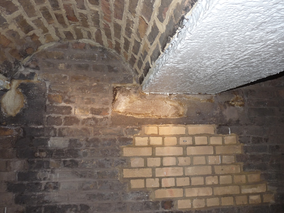
Figure 6 – Typical junction between girder, jack arch and abutment Although some of it had been repaired, the generally good condition of the exposed original 140 year old bricks suggested that they were engineering bricks. As the strength of the joint between the girder and the abutment was primarily related to the strength of the mortar, the bricks were not tested.
The calculations were revisited using the information derived in this way, and the potential for the girders to be overstressed remained. It was considered that:
- The calculations could not be improved sufficiently to guarantee that load effects induced in the girders would not be significant
- It would be possible to instrument the girders to check whether significant load effects were being induced by ground movement
- It was unacceptable to allow a brittle girder over a live railway to become overstressed
- It was unacceptable to have any significant risk that the behaviour of the structure might require tunnelling to stop while mitigation measures were implemented.
It was therefore decided to design and carry out physical mitigation works prior to tunnelling in order to reduce the risk of brittle failure or delaying the tunnelling. The works were designed to weaken the brickwork around the girder ends to the point where it could readily be shown that the girders could not be overstressed by differential settlement. Precise instrumentation was fixed to the critical girders in order to confirm that tension in the critical bottom flanges remained within acceptable limits.
Movements of the structure were monitored with 3D mini prisms attached to the abutments and girders, and an automatic total station.
As an additional safeguard it was required that the underside of the girders be inspected from track level every night during periods when the rate of ground movement was greatest. The jack arches were inspected at the same time to mitigate the small risk that deformation could allow a brick to come loose and then fall.
The assessment and mitigation design were subject to a category 3 check.
Design and installation of precise instrumentation
The primary intention of the instrumentation was to check whether any tensions were being induced into the bottom flanges of the girders, or whether the girders were moving in their axial direction relative to the abutments. Secondary objectives were to detect any strains related to differential settlement, or any strains at midspan of girders 1 and 2 due to variations in lateral bending moments. The instrumentation had redundancy built into it so that in the event of some information being doubtful there would be independent means to verify it. The chosen layout of instrumentation is shown in Figure 7.
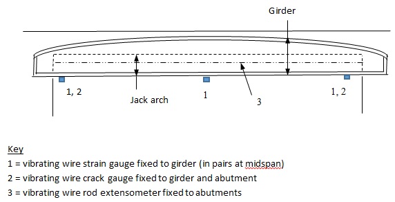
Figure 7 – Precise instrumentation installed on or near selected girders Some gauges were fixed to girders where no ground movements were expected. Their response was to be compared with gauges where movement was expected, and used to assist in isolating and removing background noise due to passing trains, temporary imposed loading above the roof, and thermal effects.
The vibrating wire extensometers were intended to provide an alternative means of determining changes in abutment separations at girder level. The vibrating wire crack gauges were intended to show what if any movement was occurring between the girders and the abutments. It was envisaged that strains in the bottom flanges of the girders times the girder lengths might equal changes in the separation of the abutments minus relative movements between the abutments and the girders.
Following careful surface preparation of the girders, the strain gauges were attached using an epoxy adhesive, as welding might have damaged the girders. The crack gauges were installed to the girders using Lindapter clamps and metal framing. The fibreglass bodies of the rod extensometers were clamped to brackets on both abutments and supported at 1 metre intervals from the jack arches. The extensometers included 30mm range displacement transducers. The cabling for the electronic devices was fed to a multiplexer, which was connected to a wireless data logger which sent the data via 3G or ADSL to a server for processing. The processed data was then transferred to and stored in a Crossrail database which could be accessed by all relevant parties.
Setting monitoring trigger values
Crossrail construction contracts embodied a traffic light system relating Green, Amber, Red and Black trigger values to pre-determined risk-mitigation actions. At CW126 a Red trigger would potentially require a halt to underground excavation, while a Black trigger would close the LO railway.
It was necessary to define a maximum permissible increase in tensile strain in the girder bottom flanges at midspan. This amount needed to be large enough to be practical, but not so large as to risk overstressing the girders. The girders at the end of the covered way were the ones most exposed to excessive tension, but also those where the existing tension was hardest to calculate. The limiting strain (90ue) chosen as the Red trigger, corresponded to approximately 9N/mm2, or a 1mm lengthening of the girder, and was justified in part by the fact that the girders appeared to have successfully carried the equivalent extra stress prior to recent load reductions. The Black trigger was not quantified in advance, and might not have related to a value measured by instrumentation.
A subsequent paper by Kirk5 cited evidence that higher tensile stresses can be used in thinner pieces of cast-iron. However a contribution by Bussel6 noted that for the thicknesses of materials normally found in bridgework, the stresses in BD21/01 remain appropriate.
Pre-construction mitigation works
In order to ensure that differential settlement could not induce excessive bending moments into the girders the joints at the girder ends were weakened. At girders 2 to 6 vertical stitch drilling as shown in Figure 8 was carried out.
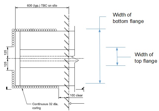
Figure 8 – Plan on mitigation works carried out at girders 2 to 6. In order to be sure that the drill holes were accurately set out it was necessary to carefully expose the top flanges of the relevant girders. This process confirmed that all the girders were embedded by the amount expected, and provided some reassurance that all the girders had the same end detail.
The gap in the drilling near the centreline of the girder ensured that there was a positive load path for compression, should that be needed. A sufficient load path remained to carry the unbalanced horizontal jack arch reaction into the abutments.
The mitigation works at girder 1 consisted of creating a movement joint through the full height of the parapet and the girder immediately beyond the girder ends.
These mitigations were also designed to provide a high level of assurance that excessive axial tensions could not be transmitted to the girders. This could not be categorically confirmed however as not all the relevant details of the girders and masonry encapsulating them could be ascertained with certainty.
Results from precise instrumentation
The responses of the vibrating wire crack gauges to temperature appeared to be inconsistent with fully built-in or fully free girders, or any intermediate condition. As a consequence this data was not relied on. For various practical reasons the results of the electronic extensometers were not useful. The strain gauges were therefore the single source of precise monitoring from which to calculate the induced strains in the girders.
The pairs of gauges at midspan at no stage gave results which suggested any change in lateral bending moments were being applied to either girder 1 or 2.
A simple calculation showed that if thermal strains in the girders were not restrained by the abutments and the retained ground, the limiting strains would be exceeded without any ground movement. The amount of restraint could not be calculated accurately. In order for the strain gauges to be useful it was necessary to find a way to distinguish the effects of ground movement from those due to temperature changes. It was fortunate that there was no live load on the girders during construction, as this would have been a third variable affecting the gauge readings.
The construction programme at first allowed about six weeks of data to be gathered that could be guaranteed to be free from ground movement effects.
Each strain gauge has its own built-in thermistor so that corrections could be made for the gauge’s own response to temperature. As a result each gauge produced a stream of strain and temperature data which could be manipulated with spreadsheets. It quickly became apparent that measured strains were not proportional to temperatures measured at the same time, suggesting that the thermal inertia of the roof was having a significant effect. A typical plot of measured strain against temperature over the six weeks is shown in Figure 9.
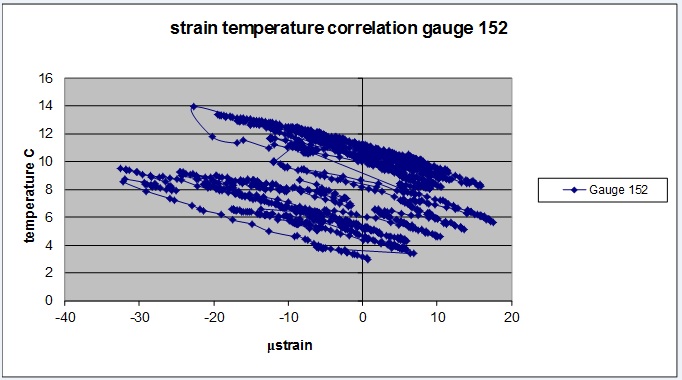
Figure 9 – Typical relationship between measured strain and temperature By making various trials it was established that good correlations could be obtained between measured strains and modelled strains, where the modelled tensile strain εm is defined as
εm = c1 – c2t +c3t96
where t is the instantaneous measured temperature, t96 is the average measured temperature over the preceding 96 hours, and c1, c2 and c3 are constants.
Figure 10 shows such a good correlation over the six week period. Not all the gauges had data which could be correlated as well as that, but many did. It was not clear why some of the gauges had data with worse correlations.
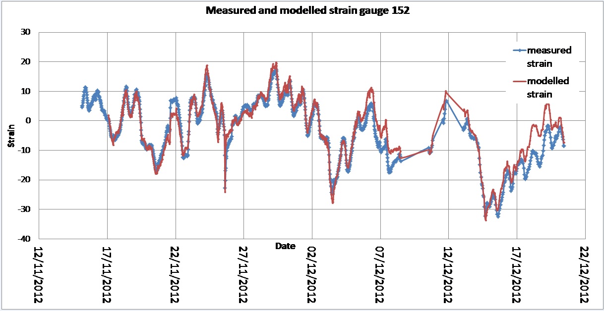
Figure 10 – Measured and modelled strains Constants c1 and c2 were always positive. Note that an increase in temperature causes the girder to expand, but by less than it would do if it were free, the gauge software is arranged to show no strain if the girder expands freely, and so an increase in temperature results in a measured compressive strain.
Various developments allowed the baseline period to be extended to six months. The constants were modified slightly using the additional data. The strains modelled using the baseline data appeared to have reliably calculated strains due to temperature effects over the next two years of ground movements.
During those two years the maximum midspan bottom flange tensile strain that was attributed to ground movement was 10 to 20µε, thereby confirming either that the stiffness of the structure substantially reduced greenfield strains, or that the mitigation works had freed the girders from the abutments.
Very occasionally the data obtained from an individual gauge was assessed as anomalous, in that it did not fit the pattern derived from adjacent gauges and other instruments, and did not follow the expected trends due to temperature changes. This anomaly was typically apparent as an initial unexplained gradual increase in compressive strain followed by a sudden large increase. These unexplained measurements were thought to show a loss of adhesion to the girder, and lead to immediate replacement of the relevant gauge.
Further mitigation works
Towards the end of construction it became apparent that ground movements were becoming more extensive than had been calculated, thus causing unmitigated girders to reach the Red trigger on differential settlement. It was possible to increase the limit on differential settlement of girder 7 by taking advantage of some features which became apparent during the pre-construction mitigation works. After a consideration of options it was decided to mitigate two further girders (nos. 8 & 9) but to measure the strain in the girders released by the mitigation works, thereby providing an indication of how conservative the assessment of this aspect was. The scheme for this is shown in Figure 11. The intention was to provide as complete as was practically possible a moment release at the east (high) end of these two girders.
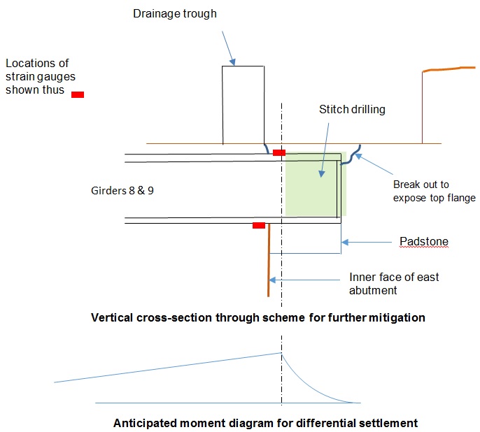
Figure 11 – Scheme for further mitigation with instrumentation There was some difficulty in getting the gauges on top of the girders to adhere, thought to be due to the ponding of surface water, but convincing information was obtained nevertheless. Two strain gauges showed a gradual change, followed by a sudden jump, during the stitch drilling. This was thought to correspond to an initial increase in flexibility of the joint, followed by a moment release as the drilling neared completion.
The gauges showed a reduction in tensile strain at the top of the girder, and a smaller reduction in compressive strain in the bottom flange of the girder. Analysis showed that the mitigation had released a hogging moment and an axial tension in the girder. The calculated moment was less than a tenth of the conservatively assessed value. The tension was less than half the upper limit assessed for girders away from the end of the covered way.
Although the evidence for these small induced stresses was limited, it was considered to be sufficiently reassuring to allow an increase in the Red trigger for differential settlement on unmitigated girders by three times, thereby ensuring that further ground movements would not bring the need for further mitigation works.
Observations on thermal response of the covered way
If the girders had been free to expand, the change in measured strain would have been zero. If they were fully restrained, it would have been approximately -11 µε/°C.
For a rapid change in temperature, as might happen during a day, the change in modelled strain per unit temperature is approximately -c2. For a slow change in temperature, such as might happen between seasons, with t = t96, the change in modelled strain per unit temperature is c3 –c2.
Away from the ends of the covered way, c2 was found to be 2 or 3 µε/°C. Near the ends of the covered way the value was mostly between 4 and 6 µε/°C. This showed that the girders were more restrained against thermal expansion near the ends of the covered way. This was thought to be the result of the continuing retaining walls being integral with the abutments of the covered way. This in turn validated the view taken in the assessment that the girders at the end of the covered way were more exposed to tension induced by ground movements.
Constant c3 was mostly in a range from 1 to 3 µε/°C.
These values have been converted into proportions of full restraint and are shown in Table 1.
Girder position Temperature change Rapid Gradual Away from ends of covered way 25% 5% Near ends of covered way 50% 30% Table 1 – Measured proportions of full longitudinal restraint of girders
Note that for a gradual change in temperature the girders at the ends of the covered way are markedly more restrained than the others. It is thought that during a gradual change in temperature the brickwork and concrete in the jack arches have the same temperature as the girders, and the stiffness of the whole roof will be relevant to and reduce the degree of restraint provided by the soil behind the abutments.
Reinstatement
It is anticipated that the covered way will be reinstated where mitigation works were carried out, but that will not happen until near the end of the overall construction process.
Conclusions
The unusual proportions and geometry of the covered way, combined with the brittle cast-iron in its roof girders made the structure particularly susceptible to damage from ground movement. The potential risks to the LO railway, and to tunnelling progress, led to simple physical mitigation works being carried out, backed up with precise instrumentation of the girders. These measures were completely successful in providing assurance of safety throughout the Crossrail works which were causing ground movement.
The key instrumentation consisted of vibrating wire strain gauges stuck to the bottom flanges of the girders. Modest redundancy in the gauges was sufficient to overcome difficulties with the occasional loss of adhesion. Simple numerical modelling enabled strains arising from changes in temperature to be distinguished from those due to ground movement. The data provided a rare insight into the thermal behaviour of the structure.
References
- Bessant G. The extension of London Underground’s East London Line. ICE Proceedings, Transport. 160.3. 101-108.
- Burland J. Assessment of Risk of Damage to Buildings due to Tunnelling and Excavation. 1st International Conference on Earthquake geotechnical Engineering. Tokyo. 1995.
- Baker B. The Metropolitan and Metropolitan District Railways. ICE Proceedings. Paper no. 2054. 1885.
- Highways Agency. BD21/01. Design Manual for Roads and Bridges – Assessment of Highway Bridges and Structures. 2001.
- Kirk M. London Olympic Park underpass leads to better understanding of cast iron. ICE Proceedings. Civil Engineering 166. 129-135.
- Bussell M. Discussion of London Olympic Park underpass leads to better understanding of cast iron. ICE Proceedings. Civil Engineering. 167.1 13
-
Authors

