Crossrail Sprayed Concrete Linings
Document
type: Technical Paper
Author:
Andrew Pickett BEng CEng MICE, ICE Publishing
Publication
Date: 03/11/2014
-
Read the full document
Introduction
In June 2009 Mott MacDonald undertook the framework design package C121 for the design of all Sprayed Concrete Lined (SCL) tunnels for the Crossrail project. Since then the design has gone through RIBA D to RIBA F and Issue for Construction design stages.
This paper introduces the scope of the work, how C121 set out the basis of design, the challenges faced and the main project design interfaces and how they were managed. It will also present how the Mott MacDonald design has been coordinated with the architecture design to meet the Architect aspirations for the overall Crossrail aesthetic.
The paper will also generally discuss details of design including the varying geology and will set out the methodology and ethos behind the design and how Mott MacDonald developed their design techniques to meet the challenges of the project while giving Crossrail best value over the design period of outline to tender, through the Optimised Contractor
Involvement stage and to Detailed design.C121 Structures
The C121 design package consisted of significant structures on the central section of the Crossrail project. C121 were responsible for designing the following structures:
• All station tunnels/ adits at:
o Bond Street
o Tottenham Court Road
o Farringdon
o Liverpool Street Station
o Whitechapel• All intermediate shafts, crossovers and cross passages
o Cross passages for running tunnel packages
o Stepney Green Crossover
o Whitechapel Crossover
o Eleanor Street
o Mile End
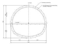
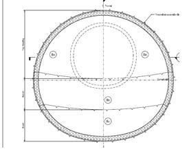
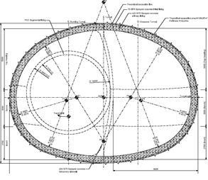
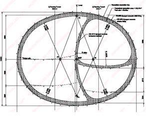
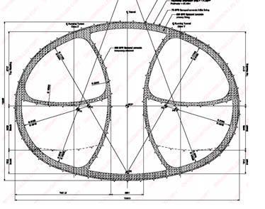
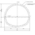
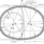
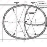
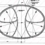
o LimmoFigure 1 shows a typical station layout (with station interfaces) and Figure 2 shows a cross section of Stepney Green Crossover.
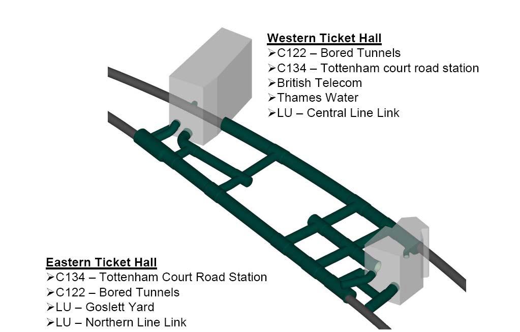
Figure 1 – Tottenham Court Road Station and design interfaces
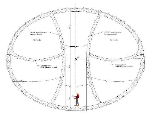
Figure 2 – Stepney Green Crossover Cavern
The platform tunnels at each station are typically 240m in length and the Stepney Green Crossover cavern will be the largest tunnel constructed in London in SCL. So the challenges at the beginning of the contract were clear, and required logical approach to the design and organisation of the C121 design team.
C121 Team
Figure 3 shows the organisation chart for the C121 design team and Figure 4 shows a typical set of interfaces for each station package.
The team had to have a robust set up to be able to meet the design challenges of designing all the structures in a consistent format. It was based around a core design delivery teams for discreet packages, which were supported consistently from specific teams such as,
Geotechnical, Environment, Construction planning and Environment. It was also supported by Design challenge teams or peer assists that would come in and take a holistic review of the Crossrail SCL structures. This facilitated an efficient consistent design delivery and enabled consistent interfaces across other design packages as shown in Figure 4.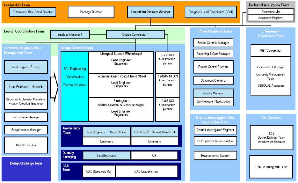
Figure 3 – C121 Organisation chart
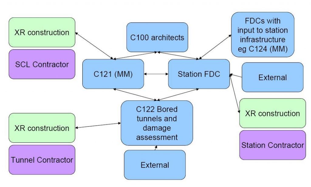
Figure 4 – Typical interfaces for one Station package
Basis of Design
Design Criteria
The Sprayed Concrete Linings (SCL) for the Crossrail Project are to be designed taking account of previous experience of the design and construction in soft ground of such tunnels. Due to being in London and the high profile of the project the consequences are high. The risks associated with SCL construction are mitigated through the use of precedent proven technologies. The tunnels are to be sized to comply with the project aims and they must be capable of being built safely and cost effectively within the programme requirements.
Safety considerations include the wellbeing of those constructing the tunnels, those people in adjacent structures (including existing tunnels) and the general public that may be affected by tunnel construction.
The priorities identified for achieving these aims were:
• Mechanise construction methods with the primary aim to keeping men away from the face, maximising safety with benefits for productivity and e.g. robotic spraying.
• Reducing men working at height, near to the face and using hand held equipment. The design minimises the number of joints in the permanent works and where possible uses fibre reinforcement thereby avoiding risks associated with traditional reinforcement installation.
• Incorporating issues of practicality for construction logistics and CDM risks for the construction and maintenance stages.
• Robust designs that are compliant with Crossrail Design Standards and current Best Practice and have an operational design life of 120 years with low levels of maintenance.
The following design techniques have been used:
• Bench marked the design against previous best practice in SCL projects and proven technologies.
• Carried out Comparative Risk Assessment to demonstrate the design risks are ALARP by assessing the safety critical activities and comparing the relative risks of different options.
• Used the current best practice methods to numerically model the ground: structure behaviour and establish the required lining thicknesses and structural requirements. Calibration of the analysis has been carried out against previous projects in London. Sensitivity analysis were carried out to establish the effects of variation in the main ground parameters selected.
• Carried out ongoing Peer reviews to allow for independent scrutiny of options.
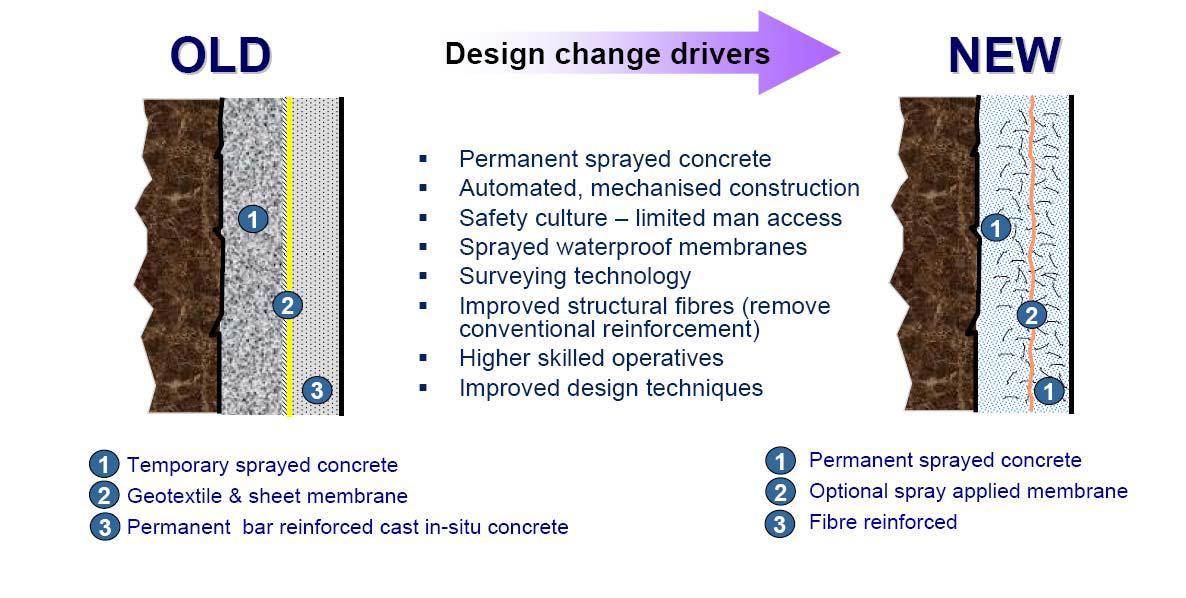
Design Drivers
The design drivers for SCL structures are as follows:
• Permanent sprayed primary linings incorporating fibre reinforcement. The external 75mm of the lining considered to be sacrificial in the long term.
• Utilising the primary sprayed concrete as a permanent lining at junctions where it incorporates standard steel reinforcement.
• Excavation face sizes based on experience and stability calculations. Where large tunnels are required, and the geometry is appropriate, the use of pilot tunnel construction sequences rather than sidewall drift construction to provide suitably sized headings.
• The use of modern electronic surveying and setting out techniques which combined with the use of pilot tunnels, eliminates the requirement for lattice girders for profile control in tunnels.
• A full design based on moderately conservative ground parameters. A sensitivity analysis to confirm that the design using these parameters is robust.
• Junction opening designs which allow later erection of the permanent structural reinforcement within a completed sprayed concrete shell, rather than during the advance of the tunnel.
• Spray applied waterproof membranes (except Farringdon and tunnels in the Lambeth Group)
• Sprayed secondary linings, where there is a sprayed waterproof membrane.
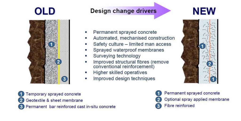
Figure 5 – Rationale for permanent primary and secondary SCL
The Design
The lining system for the SCL tunnels on Crossrail consists of a fibre reinforced primary lining, a waterproofing membrane and a fibre reinforced secondary lining. The lining system is currently a double shell lining with both linings considered part of the permanent load bearing structure. A spray applied waterproofing membrane is used in all tunnels except those found in the Lambeth Group soils, such as Farringdon Station. The linings are currently designed to share the loading, and the primary lining is considered load bearing throughout the design life of the structures. The linings are not currently designed as acting compositely where shear transfer and full bonding performance between at the interface between primary lining, waterproofing membrane and secondary lining would be required.
Primary Lining
The permanent primary lining has been designed to take the full short-term applied ground load and any other loads, such as from compensation grouting and surface surcharges, expected in the two years prior to secondary lining installation. Any additional long-term loads, such as those applied through ongoing consolidation of the London Clay, subsequent to the installation of the secondary lining is shared between the two linings, according to the results of numerical modelling.
The primary lining will be a sprayed concrete lining containing structural fibre reinforcement. The structural fibres are proposed in order to increase the ductility of the concrete and provide toughness and post crack resistance in the long term.
The excavation profile and thickness of the primary lining for each advance will be controlled using target-less remote laser scanning equipment, set up at a safe distance from the excavation face. The profile control system will be subject to testing and approval processes prior to application in the Crossrail tunnels.
Lattice girders have not been included due to the availability of modern setting/surveying techniques for shape control.
This allows for the removal of lattice girders for all tunnels apart from turnout tunnels employing sidewall drift construction sequences.
Secondary Lining
The secondary lining is designed for:
• Long term water pressure,
• Internal loads, such as mechanical and electrical equipment,
• Long term load conditions
• Temperature and shrinkage,The proportion of consolidation loading applied to the secondary lining has been calculated using numerical modelling methods. The proportion of load transferred between the two linings is a function of the interface between them, i.e. the chosen waterproofing method. A spray applied membrane which bonds to both structural linings allows a greater degree of sharing between concentric linings. A sheet membrane, which allows slip and leaves a small space between the linings will not transfer load to the inner lining to the same degree.
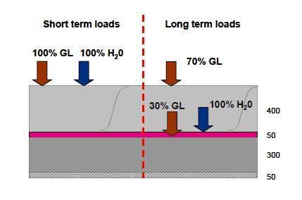
Figure 6 – Load sharing between primary and secondary SCL linings
Numerical modelling methods allow for load sharing between the tunnel lining and the ground and stress relaxation due to tunnel excavation using a sequential SCL approach. As a result, in the long term it is possible that the calculated radial pressure acting on the linings is less than the total overburden load. Values used for Crossrail modelling have been calibrated against tunnels built previously in London Clay, i.e. Heathrow, Kings Cross and London Bridge and further calibrated against 3D models of the construction sequence proposed at this stage of the design.
Secondary linings are designed to carry sufficient residual capacity to resist ground loading after a EUREKA time/temperature fire curve, as defined in the Technical Specification for Interoperability – Safety in Railway Tunnels TSI-SRT and will contain micro-synthetic fibres in order to limit explosive spalling and maintain structural integrity. It has been shown in extensive fire testing for projects such as Heathrow Terminal 5, A3 Hindhead, and CTRL that the inclusion of micro synthetic fibres in high strength, low permeability concrete mixes (such as proposed for the Crossrail linings) significantly reduces the risk of explosive spalling when exposed to severe hydrocarbon fires.
Waterproofing Systems
Waterproofing membranes will be installed between the primary and secondary linings of all SCL tunnels, both public and non-public. The waterproofing system proposed is to provide an “un-drained” lining; the groundwater will be prevented from entering the tunnel by the waterproofing membrane and not be managed in the tunnel drainage system.
Waterproofing of sprayed concrete lined tunnels has traditionally been achieved through installation of polymer sheet membranes between the primary sprayed concrete layer and the secondary cast in-situ concrete layer. However recent projects such as Hindhead have demonstrated that the developments in sprayed waterproof membranes technology have shown sprayed waterproof membranes to be as good as cast sheet membranes in low permeability geology, and therefore, to facilitate their economical use.
Much of the Crossrail SCL works are located in London Clay, or other equally low permeability strata. In many ways this makes the tunnels ideal for watertight concrete design. The advantages of a spray applied waterproofing membrane are:
• Facilitates the use of spray applied secondary linings as spraying onto sheet membranes is recognised as a difficult operation with potential risk of defects.
• The safest of the waterproofing and secondary lining options considered in the Comparative Risk Assessment, notably in terms of reducing work at height.
• A tunnel that is resistant to water ingress.
• Lowest cost option for waterproofing.
• Shortest construction programme.
• Positive precedent projects in UK and internationallyIn the case where, due to the potentially higher water permeability of the ground (for example sand channels and laminated beds in the Lambeth Group), there is a greater risk of a substrate with active water ingress a sheet membrane has been chosen as a more suitable method for waterproofing. The most significant example of this is the proposed Farringdon Station.
Design process
The design process for C121 SCL Design is summarised in Figure 7. The process described takes into account the outline design processes provided in the BTS-ICE Tunnel Lining Design Guide (2004), and the ICE Design and Practice Guide – Sprayed Concrete Linings for Tunnels in Soft Ground (1996).
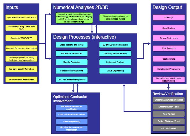
Figure 7 – Summary design process for C121 SCL Design
Expert Design Review/ Peer Review
In addition to Crossrail’s Technical Assurance procedures, for example IDRs and Constructability Reviews and Category III Design Checks, Mott MacDonald employ the additional valuable process of Peer Review on all their major projects. The Peer Review comprises recognised design and construction experts not directly involved with the project to provide an independent assessment of the design, ensuring safety, and offering improvements where appropriate.
Challenge Team
Mott MacDonald formed a team of industry experts to periodically be called upon to challenge our design philosophy and approach, but also to provide additional views and ideas that assist the SCL design development. This approach has proved highly valuable on major projects, and to date has provided expert guidance on support on the Crossrail project.
Innovation and Value management
There have been several innovative solutions that have been put forward for the SCL design, these have included those already covered within the design which have improved safety from removing men from the face and reducing working at height while giving added programme benefits, such as:
• Sprayed waterproof membranes and secondary linings
• Elimination of lattice girders
• The use of steel fibre reinforcement instead of conventional reinforcementWe have also provided innovation and design solutions which have programme and wider architectural benefits, three examples are as follows:
• Junction construction methodology
• Standardised cross sections
• Curved junctionsJunctions and Openings
The design of SCL junctions is driven by the following:
• Designed to permit no disruption to the main tunnel construction programme. Therefore this allows the primary lining to be installed without reinforcement at junctions, but enlarged locally to accommodate later installation of rebar. (Traditional design approach was to install steel reinforcement, or thickening beams “as you go” round-by-round which is difficult and can cause durability risks.
• The primary shell will be sprayed using structural fibre reinforced sprayed concrete.
• The design approach provides a safe environment for creating the opening through an already stressed main tunnel shell.
• The design is to limit the amount of ground settlement above junctions.
The design sequence for tunnel junctions is as follows:
• Construct the main tunnel with an enlargement at the opening location. During this construction no reinforcement is installed.
• Later in the programme, remove backfill and install reinforcement in the entire area around the opening and spray a thickening patch of primary lining in junction zone. This lining including its reinforcement is designed to carry all the loads up to the installation of the secondary lining, and a proportion of the ground load in the long term.
• Break-out from the main tunnel and construct the primary lining of the smaller tunnel, once thickening patch has acquired 28 day design strength.
• At a later stage, install the waterproofing system, erect reinforcement around the opening for the secondary lining, and cast or spray the secondary lining.
Installing reinforcement into the primary lining while constructing the main tunnel was rejected based on the need for men to approach the face.
The chosen method allows for the construction of the main bore to be carried out with minimal changes from a standard excavation (slight increase in profile only) and install long bars of reinforcement in the required location once the lining is at a suitable strength to safely work nearby, all without impeding the productivity of the face, and in a much more controlled environment.
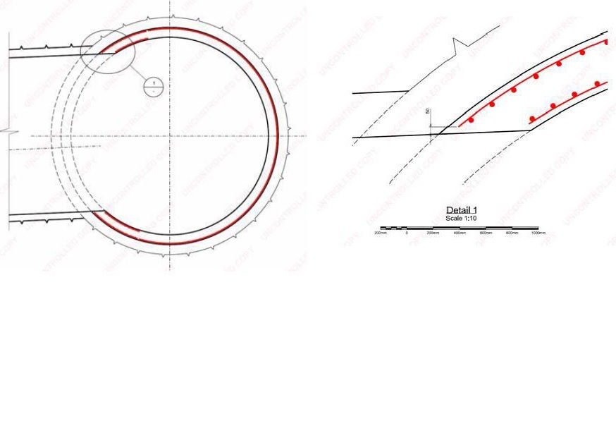
Figure 8 – Typical reinforced junction detail
Standardised cross sections
When C121 started RIBA D, there were in excess of 100 different cross sections. C121’s aspiration was to reduce the number to maximise a set of standard cross sections. By standardising the amount of cross sections there were a number of benefits as follows:
• Reducing the number of different tunnel profiles and methods required for their construction.
• Repetition makes tasks easier to remember and therefore safer and more repeatable.
• Avoiding setting out errors and confusion.
• Reducing costs of fixings and cladding through consistent solutions system wide
• Facilitating the cladding design and a platform for architectural innovation, such as curved junctions.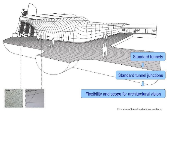
Figure 9 – Standardisation
Curved junctions
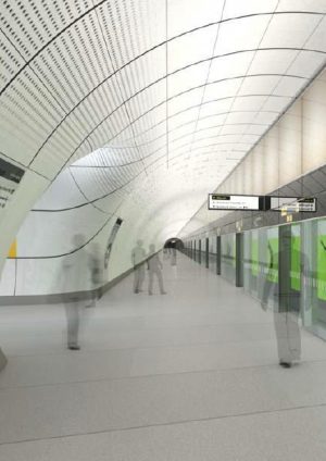
Following the standardisation of the tunnel cross sections C121 worked with the architects to provide SCL solutions for improved aesthetic and functionality (curved junctions). SCL secondary lings lend themselves to smooth transitions and rounded junctions, however on conventional design they have always been shown as right angles. C121 in collaboration with the architects maximised the reality of how SCL is formed to provide a platform for the architects to innovate and present ideas for curved cladding thereby to ease wayfinding, promote passenger flow, avoiding blind spots for improved personal safety and presenting a pleasing modern aesthetic across the Crossrail stations. An example of a platform tunnel with a curved junction is shown in Figure 10.
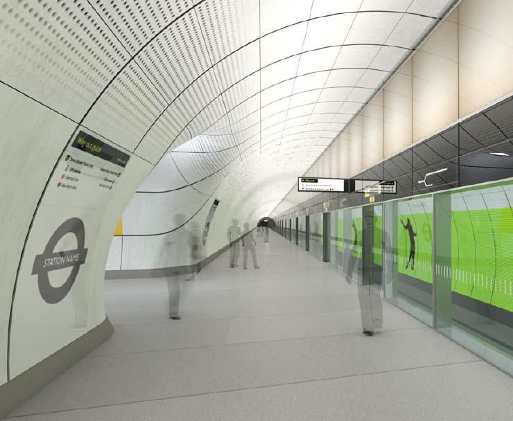
Figure 10 – Curved junctions
Value management
While a permanent SCL primary lining has a higher material cost than a conventional temporary lining by combining the following design steps there can be significant cost saving in programme. The following design steps combine to have a programme saving when compared to the conventionally reinforced temporary lining with lattice girders for shape control, sheet waterproof membrane and cast in place secondary lining, as follows:
• Steel fibre reinforced primary linings – reduces programme time for erection and fixing of conventional reinforcement.
• Junction innovation as described in ‘Junctions and openings’ reduces programme and allows no stoppage when tunnelling long tunnel drives (such as platform tunnels)
• Improved survey/setting out techniques – removal of lattice girders and therefore reduction in the erection and placement of lattice girders during primary lining installation
• Sprayed waterproof membrane – reduces programme compared with installation of sheet waterproof membrane, and allows bonding of a sprayed secondary lining;
• Sprayed secondary lining is quicker to install in comparison to placement of shutters for a cast secondary lining.
• Standardised cross sections increases familiarity for efficiency in plant and setting out.These innovations have led to typical saving of 5-8 months in programme for a typical station compared to conventional SCL tunnels, as shown in Figure 11.
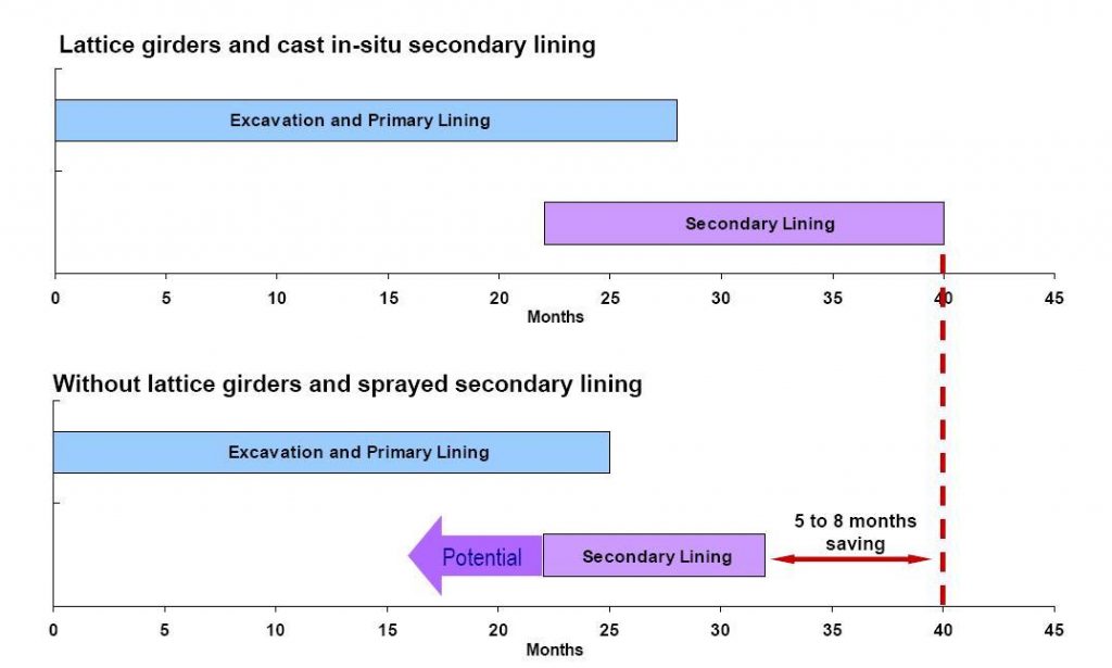
Figure 11 – Programme savings
Construction
The construction excavation sequences for the tunnels have also been standardised for differing tunnel sizes. The sequences have been chosen based on industry best practice and through a Comparative Risk Assessment CRA process to determine to meet CDM requirements as designers, examples of this were CRA carried out comparing pilot to sidewall drift techniques for tunnels up to 13m in excavated diameter. A summary of the excavation sequences are shown in Table 1.
Diameter/ span Description Typical profile Applicable Crossrail Tunnels Precedent Up to 5m Full face Service Tunnels
Temporary access/
construction tunnels
Heathrow Express Rail Link
Heathrow T5
Channel Tunnel Rail Link Ph 2
CTRL Phase 2 Wayside & Corsica Street Vent Shafts
Thames Water Tunnels –
Hampton (London Clay), Honor Oak Park (Chalk)
5 to 9m Top heading,
bench, invert
(May
include
temporary
invert strut
in top
heading)
Running
tunnel cross
passages
Station cross
Passages
Ventilation
Tunnels
Escalator
tunnels
Channel Tunnel (Chalk Marl)
Heathrow Baggage Tunnel,
Heathrow Express Rail Link,
Heathrow T5 (London Clay)
Channel Tunnel Ph I – North
Downs Tunnel (Chalk)
Channel Tunnel Rail Link Ph2 – Corsica Street Shaft – vent tunnel enlargements (Lambeth Group – silty sands)
A3 Hindhead Tunnel (Sands/weak sandstone)
9 to 13m Pilot-enlargement 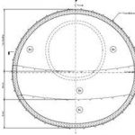
Platform Tunnels
Concourse Tunnels
Jubilee Line Extension C102 –
Waterloo Station 9.5m OD Platform Tunnels, 12.5m OD Concourse Tunnels
Jubilee Line Extension C104 –
London Bridge Station 9m OD Platform Tunnels, 12m OD Concourse Tunnels
Kings Cross Station Modernisation
7.5m OD PLA & NLA concourse, 9.8m OD NLA Escalator
12 to 14m Single
sidewall
drift
Fisher Street and Stepney Green tunnels Jubilee Line C102 – Turnout tunnels (London clay)
Jubilee Line C104 – Turnout tunnels (London clay)
14 to 18m Double
sidewall
drift
Stepney Green Heathrow Express Rail Link (London clay) – Turnout tunnels and Crossover cavern
Channel Tunnel Crossover Cavern (Chalk marl)
Table 1: Construction sequences proposed for Crossrail Project
Optimised Contractor Involvement
Due to its size and programme the Crossrail contracts did not lend themselves to traditional Early Contractor involvement, i.e. contractors being involved in the design prior to the Invitation to tender (ITT) documentation issues, therefore the Employer took the opportunity to involve the Contractor immediately after the Contract was let and during the detailed design stage of the project in the form of Optimised Contractor Involvement (OCI).
The key OCI objectives set out were as follows:
• Obtain the Contractor’s acknowledgement that the Employer’s design is buildable
• Identify opportunities for the Employer’s design to be modified to allow for safer or more cost effective construction;
• Coordinate the basis and detailed design for construction temporary works with the
Employer’s designers;
• Promote a better understanding by all parties of the contract scope
• Promote a better understanding by all parties of the potential risks and allow targeted elimination and mitigation of riskInitially this was achieved through targeted workshops followed by separate meetings to concentrate on specific issues. The advantages of the OCI process were:
• A team approach to the final solution
• Increased opportunity for innovation
• Better integration of construction methods
• Timely procurement of materials
• Fewer variations
• Collaborative approach to sustainable issues
• Reduction of construction riskConclusion
In conclusion there were big challenges faced by Mott MacDonald on commencement of the Crossrail design, through concentrating primarily on safe design by reducing the requirement for tunnel operatives at the tunnel and designing best practice with enhanced robustment. Mott MacDonald have achieved delivering a Crossrail design to programme and best value which has been benchmarked on recent SCL design in the UK such as the A3 Hindhead tunnel which successfully opening in Summer 2011.
-
Authors

Andrew Pickett BEng CEng MICE - Mott MacDonald
Design Team Leader C121, Mott MacDonald