Delivering a Safe Integrated SCL Design: The Challenges and Successes of Crossrail Contract C300/C410
Document
type: Technical Paper
Author:
Adrian St.John, BEng (Hons) Eur Ing FICE CEng, Andrew Pickett BEng CEng MICE, Andrew Kendall BEng (Hons) CEng MICE MCIHT, Vicky Potts MA MSc PhD, Damian McGirr BEng (Hons) MICE CEng, ICE Publishing
Publication
Date: 03/11/2014
-
Read the full document
Introduction
Crossrail is Europe’s largest construction project, and will transform rail transport in London, increasing capacity by 10%, supporting regeneration and cutting journey times across the city. The Crossrail route will run over 100km from Maidenhead and Heathrow in the west, through new tunnels under central London to Shenfield and Abbey Wood in the east. There will be 38 Crossrail stations including 9 new stations at Paddington, Bond Street, Tottenham Court Road, Farringdon, Liverpool Street, Whitechapel, Canary Wharf, Custom House and Woolwich.
Crossrail contract C300/C410 “western running tunnels and station caverns” was awarded to a joint venture of BAM Ferrovial Kier (BFK) in January 2011 with a value of approximately £500m. The project comprised the construction two 6.2km tunnel drives between Royal Oak and Farringdon and the construction of circa 75 sprayed concrete lining (SCL) tunnels for Bond Street and Tottenham Court Road Stations. The design for the SCL works (Primary and Secondary linings) is by Mott MacDonald (MM) as part of the C121 Framework design contract.
This paper focuses on the design of the SCL works on C300/C410 and, in particular, the way in which the project team managed a unique set of circumstances and overcame considerable technical and organisational challenges.
The SCL primary lining was designed to withstand the various temporary conditions and also formed part of the composite permanent works design. It was considered beneficial to retain design responsibility for the composite SCL primary and secondary lining design with one party (the Employer’s SCL designer, MM), whilst ensuring that the Contractor (BFK) retained responsibility for excavation and temporary support. However, such an approach also presented potential difficulties.
The approach to SCL design and construction was heavily influenced by the Health and Safety Executive (HSE) report into the collapse of NATM tunnels at Heathrow Airport (HSE, 2006). The findings of this report, combined with other HSE and ICE publications (e.g. HSE (1996) and ICE (1996)) and Crossrail Information Paper D23 (Crossrail, 2007), had a profound impact on the contractual arrangements and responsibilities for the design and construction of these tunnels.
The challenge of delivering a safe, assured and integrated SCL solution incorporating both permanent and temporary loading conditions has been overcome through close collaboration and co-operation, despite no formal contractual relationship existing between the various parties.
Contractual Arrangements and Division of Responsibility
The C300/C410 contract was based on the NEC Engineering and Construction Contract (NEC3), target contract with activity schedule (Option C). This form of contract encouraged collaboration and communication between the parties, and incentivised cost and time savings through a painshare / gainshare arrangement.
The Works Information stated that the Contractor (BFK) was not responsible for designing any of the permanent works, and was responsible for designing all temporary works. However, in relation to the SCL design, this specifically included the Employer retaining responsibility for primary SCL design at all stages of construction, including portions of lining prior to ring closure.
As part of the tunnelling industry’s drive towards delivering an efficient one-pass lining, Crossrail’s SCL design philosophy used composite action between the primary and secondary linings, and used the primary lining as temporary ground support for the part-constructed tunnels. This new approach was in contrast to previous projects which considered the primary lining as purely temporary works and, accordingly, its beneficial effects were disregarded in the permanent works design. Whilst delivering an innovative and efficient SCL design solution, this new strategy introduced a potential conflict since BFK were not only responsible for the design of all temporary works but also responsible for the safety and security of excavations at all times.
The above arrangement posed an interesting challenge for the teams; BFK were unquestionably responsible for stability and safety of the excavation, yet the temporary works consisted of a partially-constructed SCL primary lining which had been designed and checked by the Employer. This unusual arrangement caused a great deal of debate between BFK, the Project Manager, MM and the Contractor’s SCL designer (Donaldson Associates Ltd (DAL)). Clarifying and resolving this interface was one of the early challenges for the project team.
The contract included an “Optimised Contractor Involvement” (OCI) period which took place immediately after award. OCI was a Crossrail-wide initiative to gain early alignment between BFK, the Crossrail Project Manager, Employer’s designers and key members of the Contractor’s supply chain.
The key objectives of the OCI process were as follows:
• to review the buildability of the Employer’s design.
• to identify opportunities for refinement of the Employer’s design.
• to ensure alignment between temporary and permanent works design.
• to improve understanding of the contract scope and risk.A key element of the OCI therefore involved extensive workshops and discussions between BFK’s SCL engineering and SCL construction teams, MM and DAL. These initial workshops had two distinctive threads; firstly, debating the precise wording and intent of the contract in order that all parties fully understood the division of responsibilities; secondly, to seek improvements in the Employer’s SCL design in respect of buildability, sequence and methods.
A key driver was to make most efficient use of the SCL designers available within this specialist field, and keep the number of design parties involved to an absolute minimum, thereby reducing interfaces. The Employer had already appointed MM as his SCL Designer, and a significant amount of design had already been completed. For the SCL design it was necessary to consider all of the temporary and permanent loading conditions acting on both the primary and secondary lining. To provide an efficient design with load sharing between the primary and secondary linings, finite element modelling was used to ensure a more complete understanding of the lining behaviour. This entailed a number of assumptions about BFK’s preferred sequence and timing of the SCL works; these sequences were reviewed, optimised and validated during the OCI period in order to gain alignment between the parties.
In order to produce an assured design, the Employer (via MM) had engaged an independent Category III checker (URS) for the SCL design. The Category III check was predicated on an assumed sequence and, again, it was essential that this sequence was understood and agreed between all parties.
The key reasons for the approach adopted on C300/C410, illustrated in Figure 1, were thus:
• The Employer had already engaged the services of a competent SCL designer and Category III checker with sufficient resources to deliver a complete SCL design “for construction”. Employing additional designers and checkers would increase demand on scarce SCL design resource in an already over-heated market.
• In order to deliver a safe, assured design, the Employer’s design already needed to consider the primary lining at every stage of construction, both temporary and permanent.
• If the Contractor were to be held responsible for the design of all temporary works (including the SCL primary lining in its temporary state), what value would be added by employing an additional designer and a Category III checker? The main impact would be wasteful duplication of effort and resources.
• Employing additional designers and checkers would introduce confusion and potential mis-alignment of models, geometry and design information during design development, in what was already a complex and challenging interface.
Figure 1: From OCI to IFC – delivering a safe, integrated and assured SCL design
In order to clarify the design delivery philosophy, a Division of Responsibilities document was jointly prepared and signed by the relevant parties.
The key elements of this were:
• the Employer retained responsibility for the design of the primary SCL lining at every stage of construction, both temporary and permanent.
• BFK had to “understand and accept” the Employer’s SCL design. This entailed a “due diligence review” (DDR) process carried out by DAL.
• DAL (on behalf of BFK) had to design and Category II check of a set of “toolbox items” which could be deployed in response to adverse conditions encountered in the field.
• BFK had to declare that the Employer’s design was buildable, that the sequences shown were consistent with the BFK’s methods, sequences and plant, and that the “toolbox items” could be deployed without detriment to the primary SCL lining.
• DAL would provide highly-qualified “Senior SCL Engineers” and “SCL Shift Superintendents” to be embedded into the BFK Engineering team to oversee excavation stability at all times through the SRG/RESS process described later in this paper.The division of responsibilities in the context of advancing a typical SCL tunnel is shown indicatively in Figure 2, and a summary of the integrated design process is included as Figure 3; this was successfully adopted as the design delivery strategy for the C300/C410 SCL works.
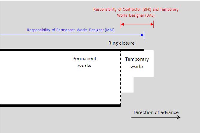
Figure 2: Typical SCL excavation sequence illustrating division of responsibilities
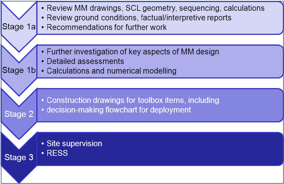
Figure 3: Integrating the permanent and temporary works via a “Due Diligence Review” (DDR) process, backed up with experienced site supervision
Design Development
At contract award the design of the SCL structures (Bond Street and Tottenham Court Road station tunnels) were at RIBA F stage (detailed design), which had been developed from RIBA D.
At this stage the design underwent a significant change to incorporate BFK’s vision for how the stations would be built incorporating the C300 running tunnel contract, which was originally a separate contract.
The original strategy was to build the station platform tunnels prior to the running tunnels. BFK however devised a solution to increase efficiency by constructing the running tunnels through Bond Street and Tottenham Court Road stations prior to the SCL platform construction, thereby using the segmental running tunnels through the station as platform pilot tunnels. This delivered considerable cost and programme savings, reduced settlement by 30%, took 90,000 lorry movements off the road and was a key factor in the BFK winning bid combining C300 with C410 into a single integrated contract.
The programme however did allow for some of the station SCL works to be carried out prior to the TBM running tunnel arrival. The OCI period following RIBA F design therefore worked towards ensuring that the original design met the aspirations of BFK and also provided new solutions to carrying out the SCL works under the new overall construction sequence and for the pre-TBM SCL advance works.
As a consequence of the above, the design was developed in two strands:
1. Contractor’s preferred excavation sequences and advance rates
2. Design options for SCL advance works (discussed in more detail in section 7 of this paper)Due to the complex nature of SCL design in clay, arising from the time dependent natures both of loading from the ground and the strength gain of shotcrete and the interaction of these effects, MM had to form a basis of design in relation to both the general excavation sequence and advance rates as follows:
Following industry recommendations (ICE, 1996), excavation faces were limited to a maximum of 30m2. The tunnel excavation sequences were categorised as follows:
• <5m diameter:- full face
• 5m-7m diameter:- Top heading / invert
• 7m-9m diameter:- Top heading / bench / invert
• 9m-12m diameter:- Pilot tunnel / top heading / bench / invertDuring the OCI process, a number of refinements were proposed by the contractor to improve efficiency and to suit his preferred plant and method of working.
An example of this was optimisation of the enlargement of the platform tunnels. The “TBM first” scheme provided a much larger pilot tunnel than was originally envisaged. This reduced the excavation required for enlargement sufficiently that the platform tunnel excavation sequence could be optimised to a pilot / top heading / invert sequence, i.e. eliminating the bench stage. This refinement was proposed by BFK and then verified as acceptable by MM to the SCL design.
BFK’s proposed advance rates were generally faster than those originally assumed by MM. MM therefore carried out 3D numerical modelling to check how the load being experienced on the tunnel varied with the early age of the SCL. In most cases MM were able to adopt BFK’s proposed advance rates.
Changes incorporated into the design had to be re-issued at RIBA F and were subject to Crossrail’s design assurance process, which included two main areas:
• Coordination with interfacing Framework Design Consultants (e.g. the designer of the Bond Street Station box and Station architecture (including the spaceproofing of tunnels))
• Revised Category III checkCo-ordination issues mainly related to ensuring that the space provided inside the tunnels remained the same (to satisfy functional requirements) and adapting the SCL – station box/ticket hall connections to suit the programme changes e.g. tunnelling out of a station box as opposed to tunnelling up to a station box.
Due Diligence Review
The purpose of the Due Diligence Review undertaken by Donaldson Associates Ltd (DAL) was to develop a detailed understanding of:
• the SCL design basis/philosophy
• the design assumptions and any constraints or limits these might impose on the design
• the anticipated behaviour of the excavation and lining (assessment of convergence of the tunnel lining, lining loads and ground movements)
• the sensitivity of the design, for example to changes in advance rate or ground conditions
• design risks associated with the SCL tunnelling for each tunnelThis would then trigger a buildability review undertaken by BFK, inform the subsequent design of “toolbox items”, describe in Section 6 of this paper, and assist personnel (Senior SCL Engineers and SCL Shift Superintendents) on site during construction in interpreting observed behaviour. A complete Category III check on the design had already been undertaken and it was not intended to repeat this exercise. For this reason the DDR was limited to considering the behaviour of the ground and lining up to the point of ring closure for the lining, as indicated in Figure 2 (i.e. the primary lining has been completed around the full perimeter of the excavation in accordance with MM’s design, drawings and specification).
The DDR process is broadly outlined in Figure 3. The review was based on the following information, supplied by MM:
• Drawings
• Design basis reports
• Numerical modelling reports
• Geotechnical factual and interpretative reports
• Defined advance rates
• Defined performance and strength criteriaInitially DAL undertook a high level review of this information to identify areas of the design that were complex or higher risk. For each tunnel the geometry, ground conditions, excavation sequence and key risks were collated during this phase of work, together with technical queries on the MM design. A series of workshops were then held between DAL, BFK, MM and Crossrail to discuss the issues identified during the initial review, again on a tunnel by tunnel basis. This allowed DAL to evaluate the conditions across the various sites and identify key issues, as well as critical tunnels (based on geometry, excavation sequence and ground conditions), for further consideration. These were selected to ensure that a full range of design scenarios were assessed to develop a detailed understanding of the lining behaviour and design constraints, without analysing each individual tunnel. For example, the geometry and ground conditions for all parent-child junctions were considered to identify a worst case for further assessment. Similarly critical tunnel sections for each of the excavation sequences listed in section 3 of this paper were selected on the basis of the ground conditions and the design primary lining thicknesses and geometry.
To complete this review DAL undertook their own numerical modelling of those tunnels considered critical, as well as looking at key issues across the full contract (e.g. junction design, reinforcement at joints). The numerical models created by DAL were used for parametric studies to develop an understanding of the lining response to various conditions (for example changes in advance rate, strength criteria, poor ground conditions) and assess the sensitivity of the design to these different factors. Where necessary, additional meetings and workshops between all parties were held in relation to specific aspects of the design. These meetings generally related to the most complex, and consequently highest risk, tunnels, and the workshops allowed all parties to collaborate to find safe methods of addressing the risks that were considered acceptable from both a design and a construction perspective.
At the end of this process the concerns identified during the initial screening were reviewed on a tunnel by tunnel basis to ensure that all had been addressed. DAL produced a DDR certificate, declaring understanding and acceptance of the Employer’s design for each tunnel.
Design of “Toolbox Items”
Having completed the DDR for a given tunnel, DAL were then in a position to design temporary measures or “toolbox items” to improve excavation stability, without compromising the permanent lining, as indicated in Figure 1.
“Toolbox item” Notes Spiles To prevent blocks of clay falling into the excavation; to be used in conditions where potential block sizes are considered likely to exceed the capacity of the initial lining indicated on the MM drawings. Spiles must not intrude into permanent lining. Face dowels Needed to ensure face stability in poor ground conditions (soft clay, or other materials in the face). Pocket excavation Depressurisation To prevent water ingress and/or heave of the invert (if water-bearing soils present in sand channels below tunnel) or face (if water-bearing soils present ahead of face), Table 1: “Toolbox items” used in C300/C410
At Bond Street and Tottenham Court Road stations, these “toolbox items” would only ever be utilised if ground conditions proved worse than anticipated. In order to deliver the philosophy of an assured engineering design prior to construction, these “toolbox items” were fully designed and Category II checked for each tunnel. This provided the site team with the flexibility to deploy these items if worse than expected conditions were encountered (see section 6 on Construction and Supervision). This meant that an assured and integrated temporary works design was available at all times, even in unexpectedly adverse conditions, and without causing a delay to works. The “toolbox items” are briefly summarised in Table 1.
The most adverse conditions considered in the temporary works design were defined by the Geotechnical Baseline Reports for Bond Street and Tottenham Court Road Stations.
Inevitably the design process could not eliminate all construction risks. The “toolbox items” described above mitigated some of the risk inherent in the SCL design for the permanent works; however residual risks remained that could not be addressed through either permanent or temporary works design.
One further advantage of the DDR process was that risks were identified at an early stage and discussed extensively throughout the process at meetings and in workshops. Residual risks were collated into CDM risk registers, and highlighted on construction drawings. In order to make this risk and knowledge transfer more effective, BFK instigated a series of workforce briefings which were delivered jointly by DAL and MM. These covered residual design risk and SCL design intent, and ensured a high degree of understanding of these key issues by the construction and supervisory teams from Crossrail, BFK, DAL and MM.
Construction and Supervision
Upon completion of the DDR process, BFK prepared a “buildability declaration” confirming that the DDR was complete, that BFK were satisfied that the Employer’s design was buildable and compatible with the “toolbox items” and that, from a design perspective, a complete, integrated, assured “for construction” SCL design could be released to the site team. This was ratified by the Crossrail Project Manager. The full process of completing this design assurance is included in Figure 4.
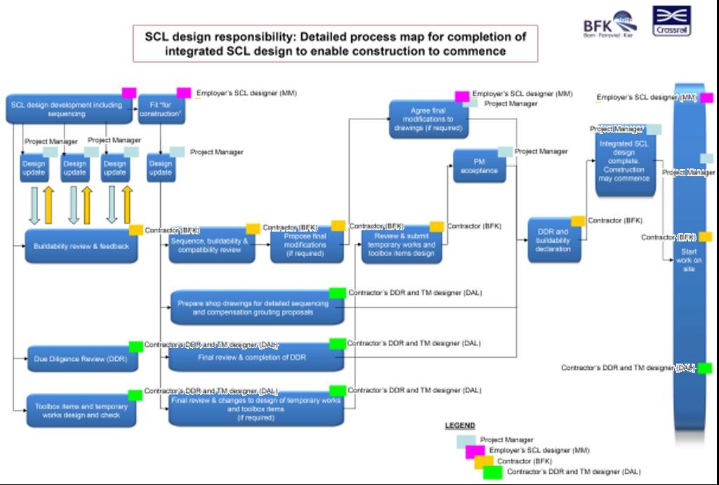
Figure 4: Detailed process map to deliver an integrated and assured SCL design incorporating both temporary and permanent works
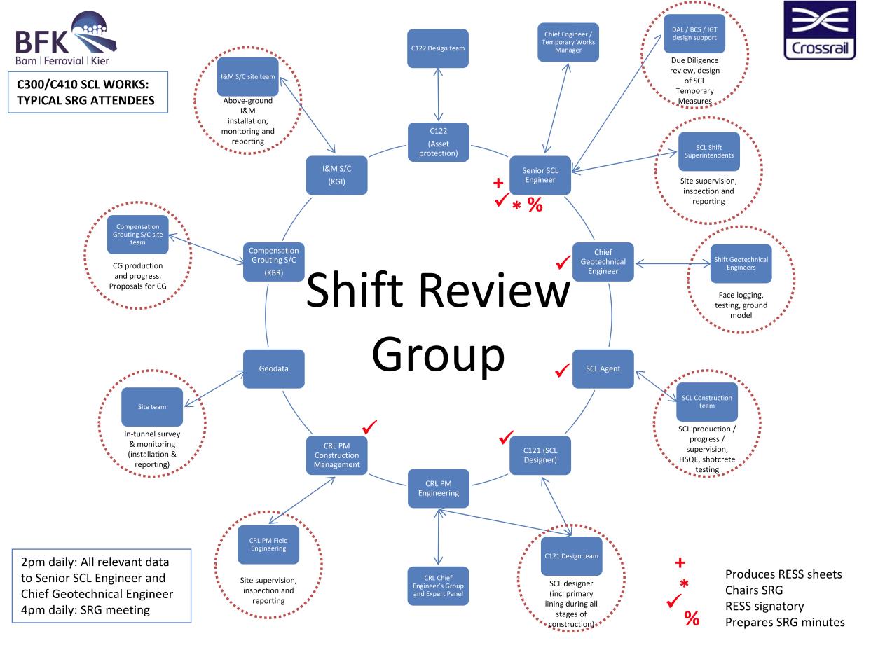
The “Shift Review Group” (SRG) and “Required Excavation Support Sheet” (RESS) constituted a critical aspect of the safe construction of the SCL works. The members of the SRG are illustrated in Figure 5.
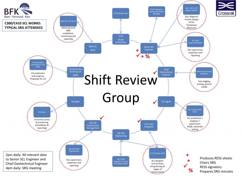
Figure 5: Typical attendees and flow of information for the SCL “Shift Review Group”
The purpose of the SRG was to review the relevant data from the previous day’s activities and to agree a plan to safely advance the tunnels for the coming 24 hours. Excavation stability and asset protection were paramount, and excavation works could not proceed without a valid RESS.
This entailed detailed co-ordination between the surface and sub-surface monitoring team, the compensation grouting team, the SCL primary lining designer (MM), the geotechnical team, surveying team and construction team. In order to achieve an effective and efficient sharing of information, each party uploaded its relevant data onto a “collaboration server” two hours prior to the SRG; this information was reviewed by all parties and, on that basis, a preliminary RESS was prepared by the Senior SCL Engineer. The Senior SCL Engineer then chaired the SRG meeting, and made the required changes to the RESS to obtain the necessary acceptance and signatures to validate and issue the RESS to the site.
Key elements of this process included:
• The Crossrail SCL philosophy was that the assured design should not be changed in the field; any changes should be limited to the deployment of additional “toolbox items” to improve excavation stability.
• Certain changes to the SCL design were permitted, but were documented carefully with due regard to the designer and Category III checker. Such changes, by their nature, were comparatively slow to implement and thus were thus avoided if possible.
• The performance of the primary SCL lining was monitored on site against in-tunnel convergence trigger levels that had mitigation actions to be implemented if they were exceeded. Both Crossrail and MM employed field engineers and inspectors to monitor the SCL works.
• Careful communication between the compensation grouting team and SCL construction team was essential to ensure that the grouting exclusion zones were respected.
• The Senior SCL Engineer reported through the BFK Engineering team to maintain a degree of independence from the BFK SCL construction team. The Senior SCL Engineers covered dayshifts only (12/7) but were supported on a 24/7 basis by the SCL Shift Superintendents.
• “Toolbox items” could be deployed at the direction of the Senior SCL Engineer and/or the SCL Shift Superintendent.Despite the complexity of the arrangements, the site teams rapidly established themselves into effective working relationships, and this model has been successfully used throughout the SCL works on C300/C410.
Example Case Study – AP3A and AP1 Wraparounds
As mentioned in section 3 of this paper, as a result of the change in overall sequence (adoption of the “TBM first” scheme), the SCL station tunnel design had to be adapted to provide additional design solutions to carry out the pre-TBM SCL advance works.
In each case MM met with Crossrail, BFK and DAL to review BFK’s aspirations and to review best these might be implemented whilst minimising the impact on the following interfaces:
• Station and spaceproofing interface
• Third party assessment (through the impact of ground movement induced by tunnel construction)This case study discusses one of these pre-TBM initiatives; the AP3A wraparound (Bond Street) was successfully developed from concept to detailed design. The wraparound design met BFK’s requirements, and was acceptable to interfacing parties, the CAT III checker and subsequently also the client’s Expert panel review.
AP3A Wraparound Design
Figure 6 shows the layout at the Eastern Ticket Hall prior to the revisions due to pre-TBM advance works.
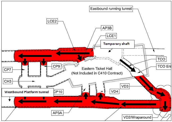
Figure 6: Eastern end of Bond Street Station – original scheme
The layout shows the westbound platform tunnel being constructed via TCO and VD3, with AP3A driven back towards the Eastern Ticket Hall.
In collaboration with the Bond Street Eastern Ticket Hall contract, early access was made available to C300/C410 from the “Master Plan Shaft”, at the western end of the Eastern Ticket Hall shown in Figure 7. This meant there was alternative access to construct the platform enlargements, which led to the conception of the AP3A wraparound solution. Figure 7 shows the plan of the wraparound; this gave BFK flexibility to construct the westbound platform from an alternative access.
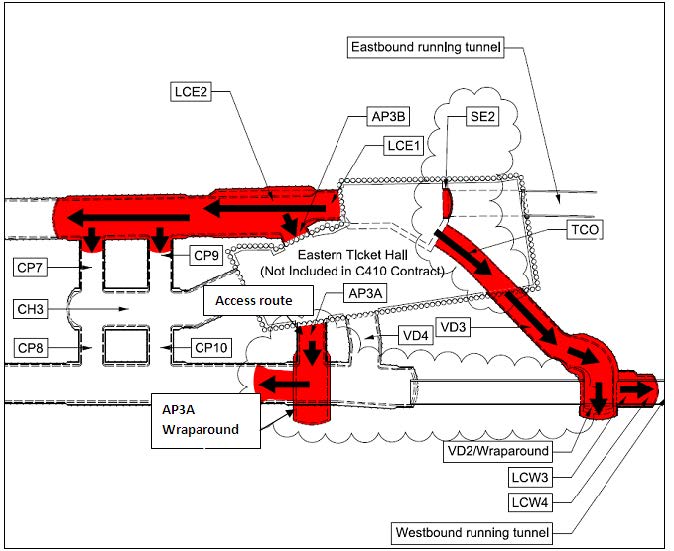
Figure 7: Eastern end of Bond Street Station – showing the AP3A wraparound
The wraparound design was subject to the following constraints and challenges:
1. Short design period
2. Design assurance – Category III checking and Crosssrail “gate” within the short design period
3. Stringent settlement criteria
4. Westbound TBM programmeThe short design period meant that the design had to consider how quickly it could be designed and Category III checked. The preferred solution may have been to design a wraparound large enough to build the platform tunnel from a typical parent-child relationship. With the typical maximum ratio between the parent and child tunnel height being 0.7 this would equate to the wraparound cross section being a minimum of 14-15m in height (the platform tunnel being 11m high). MM had experience of a wraparound this large on the C510 Crossrail contract but this required extremely time-consuming and sophisticated numerical modelling. This was not a viable option given the programme constraints. This coupled with the increased settlement due to the larger excavation, and the close proximity of a critical and sensitive Grade II* listed structure (20 Hanover Square) above meant an alternative solution was required.
The preferred solution was to provide a smaller wraparound which was suitable for a child tunnel large enough to accommodate the TBM, which could then be enlarged to full platform size at a distance from the wraparound. This would provide a chamber for commencing the future platform enlargements once the TBM had reached Farringdon. The principal benefit of the AP3A wraparound solution was that it provided BFK with a safe and convenient means of commencing platform tunnel enlargement. It also allowed some flexibility to suit the TBM advance rate.
The main challenges to overcome with this design were as follows:
1. Provide access for platform enlargements
2. Safe break-in of the TBM
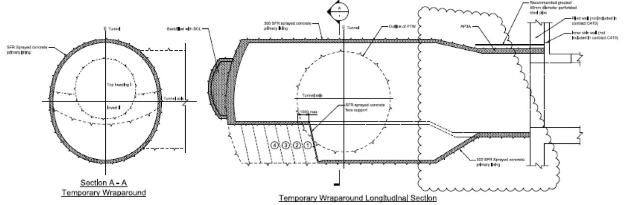
3. Once platform enlargements had occurred to the west of the advance chamber, how to construct the platform tunnel and permanent works junction to AP3A back through the temporary wraparound structureThis was solved through the following excavation steps, summarised in Figures 8, 9 and 10:
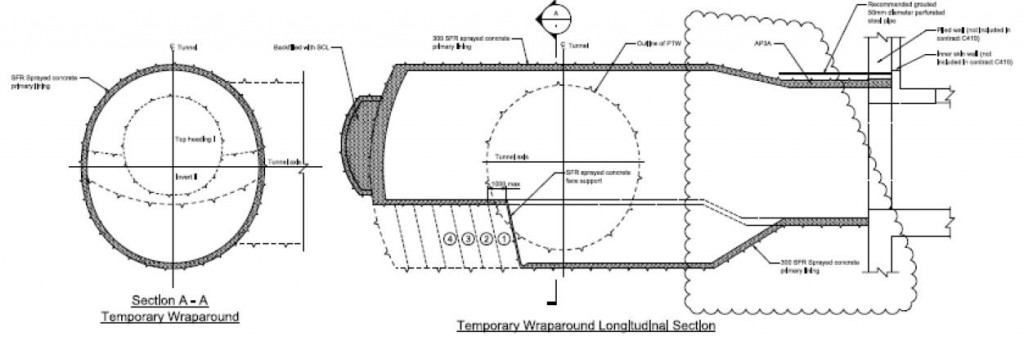
Figure 8: AP3A wraparound construction
Figure 8 shows the general excavation sequence for the wraparound from the Eastern Ticket Hall, comprising pilot tunnel, top heading, bench/temporary invert and finally permanent invert. The temporary wraparound structure provided an ideal starting point for the advance chamber SCL works.
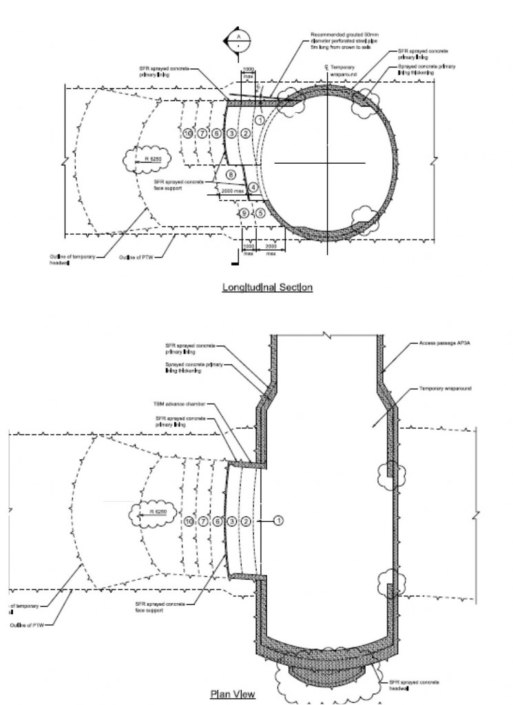
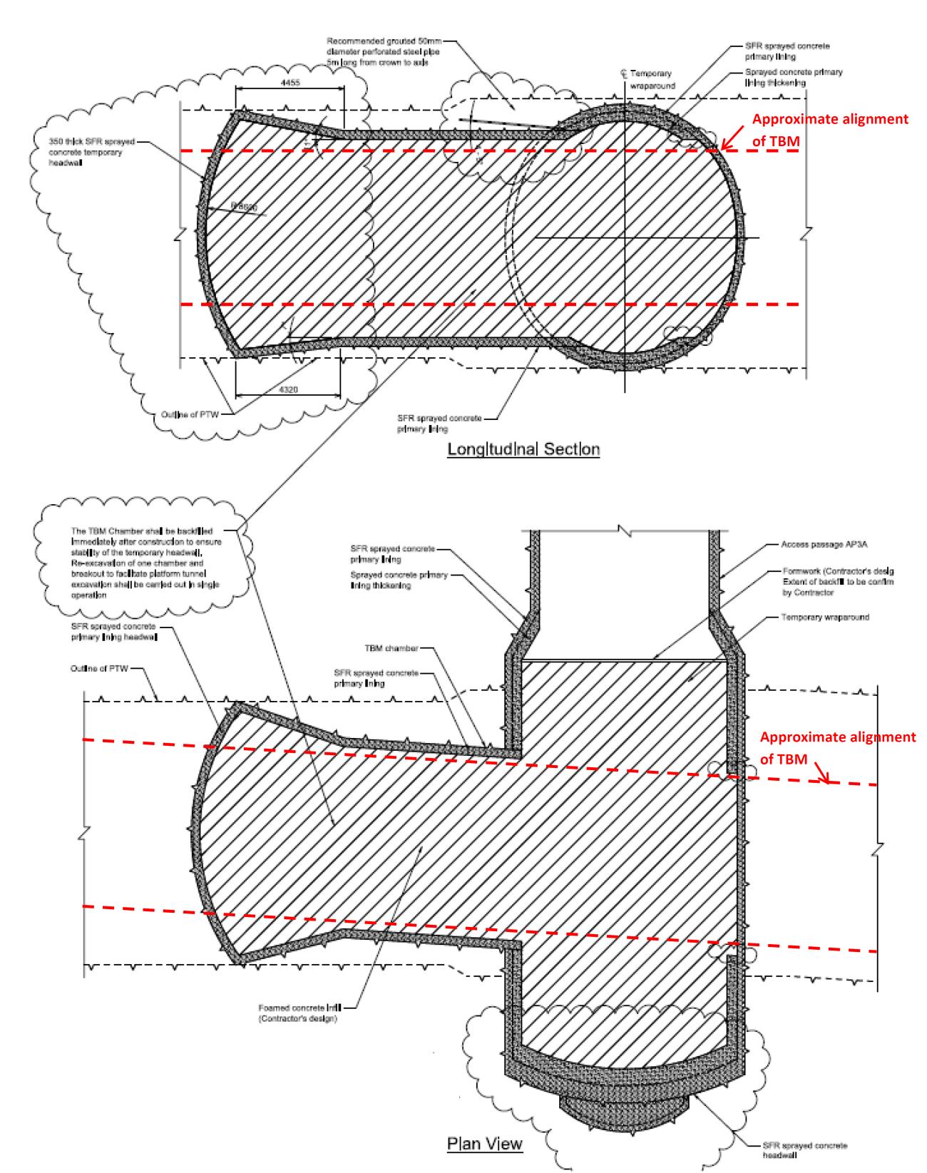
Figure 9: AP3A wraparound advance chamber construction
Figure 9 shows the excavation steps for the advance chamber out of the wraparound structure which flared to the full platform section. Once completed, the advance chamber was backfilled with foam concrete to allow the TBM to pass through rapidly and without interruption, creating a ‘pilot’ tunnel (see Figure 10).
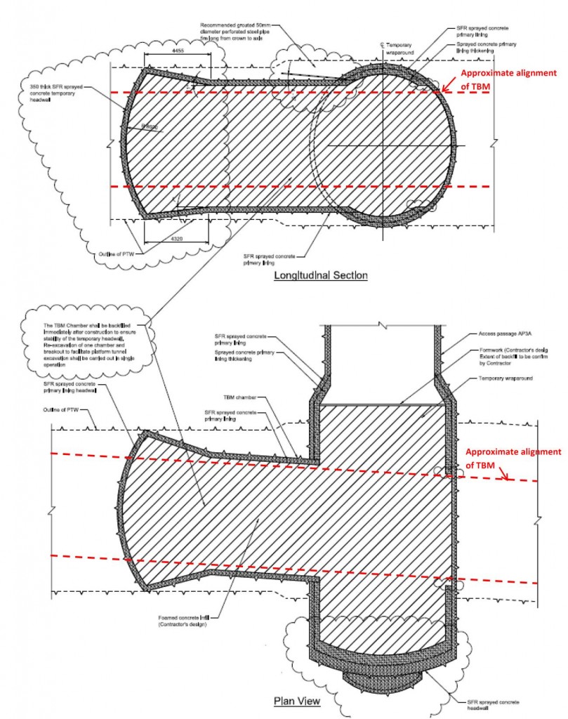
Figure 10: TBM passage through AP3A wraparound and advance chamber
Discussion – AP3A Temporary Wraparound Design
The temporary wraparound design was an excellent example of collaboration between the Client, two adjoining Crossrail Contractors, the permanent works Designers and the Contractor’s temporary works designer. This produced innovative SCL design, meeting the needs of all parties and delivered significant cost and time savings.
Subsequently this design provided enough flexibility to be employed elsewhere on C300/C410, e,g, Tottenham Court Road AP1, providing further benefits and flexibility to the Crossrail construction programme.
Conclusions
A novel approach to design management has been developed for the SCL works under Crossrail contract C300/C410 “western running tunnels and station caverns”. This arose because the use of the primary lining in the permanent scheme made it desirable for the designer to retain responsibility for the lining in its temporary state, however the contractor and his designer clearly retained responsibility for excavation stability.
To deliver an assured and integrated design whilst satisfying the requirements of all parties in view of their responsibility, and avoiding duplication of effort given the assured nature of the permanent works design, a bespoke integrated design management procedure was developed. This involved a due diligence review of the final SCL design by the contractor’s designer to develop a detailed understanding of the SCL design, development of assured “toolbox item” design to complement the permanent works, construction supervision and a clear definition of responsibilities during construction.
This unusual division of responsibility necessitated a high level of interaction between the designer (MM), the contractor (BFK) and the contractor’s designer (DAL). In spite of no formal contractual relationship existing between some of these parties, and the complexity of the process developed to satisfy the division of responsibilities, the process has been successfully implemented for C300/C410. This is illustrated by the example of the AP3A temporary wraparound at Bond Street.
It is recognised that this solution arose from an unusual set of circumstances and that adopting the same approach may not be appropriate for other projects. Nonetheless continued advances in tunnel lining design mean that similar scenarios in terms of using the primary lining as permanent works will arise again, and the integrated design management process described in this paper is one successful approach that should be considered and developed further.
List of Notations
BFK Bam Ferrovial Kier JV (Contractor)
DAL Donaldson Associates Ltd, in conjunction with specialist sub-consultants IGT Geotechnik und Tunnelbau, and Bernd Strobl Ingenieurleistungen (Contractor’s Temporary Works Designer)
ICE Institution of Civil Engineers
HSE Health and Safety Executive
MM Mott MacDonald (Permanent Works Designer)
SCL Sprayed Concrete Lining
TBM Tunnel Boring Machine
URS URS (Category III checker for Permanent Works Designer)References
Association of British Insurers and the British Tunnelling Society (2003). The Joint Code of Practice for Risk Management of Tunnel Works in the UK.
Crossrail (2007). Crossrail Information Paper D23 – Sprayed Concrete Linings.
ICE (1996). Sprayed Concrete Linings (NATM) for Tunnels in Soft Ground, an ICE Design and Practice Guide. ThomasTelford.
HSE (1996). Safety of New Austrian Tunnelling Method (NATM) Tunnels: a review of sprayed concrete lined tunnels with particular reference to London clay.
HSE (2000). The collapse of NATM tunnels at Heathrow Airport: A report on the investigation by the Health and Safety Executive into the collapse of New Austrian Tunnelling Method (NATM) tunnels at the Central Terminal Area of Heathrow Airport on 20/21 October 1994. -
Authors

Adrian St.John, BEng (Hons) Eur Ing FICE CEng - BAM Ferrovial Kier
Adrian St.John is a Fellow of the Institution of Civil Engineers and a Supervising Civil Engineer. He has spent most of his 24 year career working on major infrastructure and tunnelling projects in the UK and overseas, including the Brighton Stormwater tunnel and High Speed 1 at St Pancras. He spent 6 years as Chief Engineer for BFK Joint Venture who were the main contractor on Crossrail contracts C300, C410 and C435, and is the Design Director for Carillion Eiffage Kier (CEK) Joint Venture bidding for the forthcoming HS2 main civil works.

Andrew Pickett BEng CEng MICE - Mott MacDonald
Design Team Leader C121, Mott MacDonald
Vicky Potts MA MSc PhD - Donaldson Associates Ltd
Donaldson Associates Ltd
Damian McGirr BEng (Hons) MICE CEng - Donaldson Associates Ltd
Donaldson Associates Ltd