Design and construction of Fisher Street crossover cavern on Crossrail contract C300/C410, London
Document
type: Technical Paper
Author:
Adrian St.John, BEng (Hons) Eur Ing FICE CEng, Wolfgang Weinmar, MSc, Daniele Fornelli, MSc (Hons), Damian McGirr BEng (Hons) MICE CEng, ICE Publishing
Publication
Date: 31/08/2016
-
Read the full document
Notation and glossary
ALARP As low as reasonably practicable
BIM Building Information Modelling
BFK BAM Ferrovial Kier joint venture, the Main Contractor
DAL Donaldson Associates Ltd, the Contractor’s SCL designer
DDR Due Diligence Review
C121 Mott MacDonald, the Employer’s SCL designer
EB Eastbound binocular tunnel
EBX Eastbound crossover cavern
FIS Fisher Street
IGT IGT Geotechnik und Tunnelbau, Austrian SCL specialist partner for DAL
PCC Precast concrete
PM Project Manager
SCL Sprayed Concrete Lining
SRG Shift Review Group
TBM Tunnel boring machine
WB Westbound binocular tunnel
WBX Westbound crossover cavernIntroduction
The Fisher Street crossover cavern formed a significant part of the £750m Crossrail contract C300/C410 “Western Running Tunnels and Station Caverns” which was delivered by BFK Joint Venture between January 2011 and October 2015.
The project works comprised the construction of two 6.2m diameter 6.4km long tunnel drives between Royal Oak and Farringdon and the construction of sprayed concrete lining (SCL) tunnels for Bond Street and Tottenham Court Road Station, together with an SCL crossover cavern between the running tunnels at Fisher Street (see Figure 1).
Figure 1 – Plan view of C300/C410 running tunnels, with crossover and Fisher Street shaft (connected to running tunnels via intervention adits IA1 and IA2) Donaldson Associates (DAL) was appointed as BFK’s SCL designers for these works, with their Austrian partner IGT Geotechnik und Tunnelbau Consulting Engineers providing a number of key site supervisory staff. DAL’s scope of work comprised a Due Diligence Review (DDR) of the Client’s SCL primary lining design, which formed part of the permanent works, and the design of “Toolbox items” and any other necessary measures required wherever an unacceptable risk of instability during excavation was identified[1]. To supplement this, a 24/7 team of Senior SCL Engineers and SCL Shift Superintendents from DAL and IGT were embedded into the BFK engineering team.
This paper describes some of the key challenges and lessons learned from the design and construction of the complex 15m wide SCL crossover caverns beneath sensitive London buildings without the provision for Compensation Grouting.
These challenges included geometric complexity, reinforcement congestion, joint detailing and detailed SCL excavation sequencing including phased demolition of the temporary sidewall.
Open face SCL excavation through the Lambeth Group posed a considerable risk of encountering water-bearing sand channels. This risk was mitigated through the use of probing ahead combined with targeted depressurisation. The use of a TBM pilot tunnel and a sidewall drift limited the face area, thus improving face stability, enabling rapid ring closure and reducing surface settlement[2].
The project team used 3D printing and 3D visualisation techniques to achieve alignment between the designer’s requirements and the Contractor’s surveying systems.
The paper examines the successes of the project, and highlights a number of useful “lessons learned” which may benefit future similar projects.
Design development
From Contract Award onwards both BFK and Donaldson Associates provided significant input to the evolution of the Employer’s SCL design, both in terms of sequencing, buildability and Due Diligence Review[1].
The key elements of the permanent works included the following (see Figure 2):
- TBM pilots through both the eastbound and westbound caverns. The benefits of such an arrangement are discussed in detail in St.John et al[2].
- Enlarged SCL caverns (WBX / EBX) with constantly flaring profile. This commenced using a top heading, bench and invert sequence which then changed to sidewall drift construction once the cavern became too wide.
- Binocular sections (WB / EB) with a central wall connecting the crossover tunnel with the main running tunnel.
- Crossover tunnel, using top heading and invert sequencing.
- Niches (2 no.)
- Cross passages (2 no.)
Figure 2 – Plan view showing WBX, WB binocular, CP1, CP2, niches, EB binocular and EBX The elevation of the crossover structures put the top headings typically within the London Clay, with the bench/invert sections being located within the Lambeth Group. The original concept also included the provision for compensation grouting within the London Clay above the crossover. Post-contract award analysis of settlement predictions and damage categorisation of the nearby assets indicated that the Compensation Grouting could be deleted over the crossover caverns. Somewhat unusually on Crossrail, this resulted in a 15m wide SCL cavern being constructed within central London at a depth of only 20m, directly beneath sensitive buildings, yet without any provision to mitigate ground movements caused by tunnelling save for changes in construction sequence and the deployment of toolbox items.
One of the key residual risks of this design was the possible presence of pressurised water-bearing sand lenses within the Lambeth Group. To mitigate this risk, BFK and DAL developed a detailed probing ahead and de-pressurisation strategy to reduce the residual risk as low as reasonably practicable (“ALARP”). This strategy was developed following a detailed review of the available factual data and included a bespoke pattern of drilling arrays which could, if necessary, be adjusted in the field depending upon the conditions encountered (see Figure 3). This strategy ensured that any sand lenses intersected during the drilling / probing operations would be safely locally de-pressurised offline, ahead of tunnelling; any pressurised water-bearing sand lenses not intersected during the drilling / probing operations would thus be sufficiently small to have only a very localised impact on stability of the open face. On this basis, all parties were satisfied that the residual risks were ALARP.
Figure 3 – Plan and section showing depressurisation strategy and geology (London Clay overlying the Lambeth Group clays, with the interface occurring near axis level) The original design concept included the mandatory use of lattice girders, for a combination of profile control and structural support. A particular aspect to the cavern geometry was a relatively flat crown and invert, and continually-changing 3D profile which splayed in both horizontal and vertical directions in a non-linear manner (see Figure 4). Through the design development phase, the curvature of the crown and invert was increased. Nevertheless, the degree of curvature remained significantly less than other similar Crossrail SCL structures (see Figure 5). Another key development was the removal of the lattice girders. These were no longer required structurally but their presence caused considerable debate in relation to the health and safety implications of their installation and, if deleted, the Contractor’s ability to control the tunnel profile during excavation and spraying. Through the Crossrail “SCL Working Group”, a lessons learned study from another contract gave compelling reasons why they should be deleted. This view was shared by both BFK and DAL; however, the final decision to delete the lattice girders was ultimately based on BFK’s demonstration that their surveying methods were robust enough, and capable of controlling and delivering the required complex geometry. In the event, this decision proved to be wise, and BFK’s surveying techniques and technologies proved capable of delivering the required control and precision to construct these tunnels to the required standards, although particular difficulties were encountered at the crown joint at the top of the temporary sidewall.
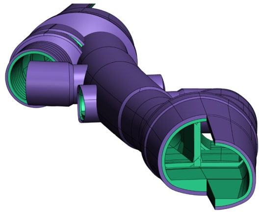
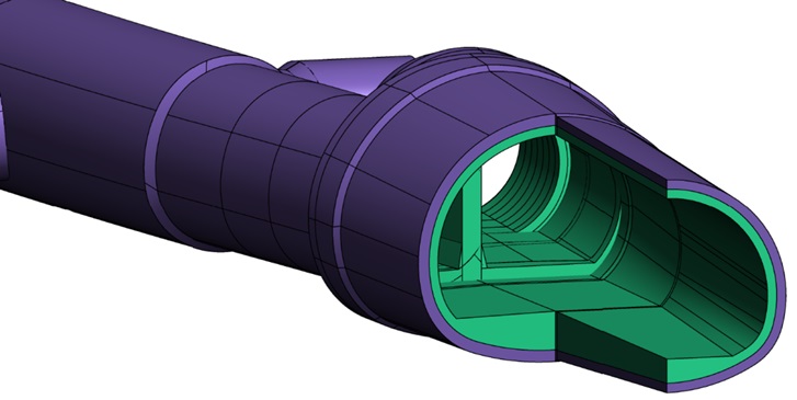
Figure 4 – 3D model views of Fisher Street crossover 
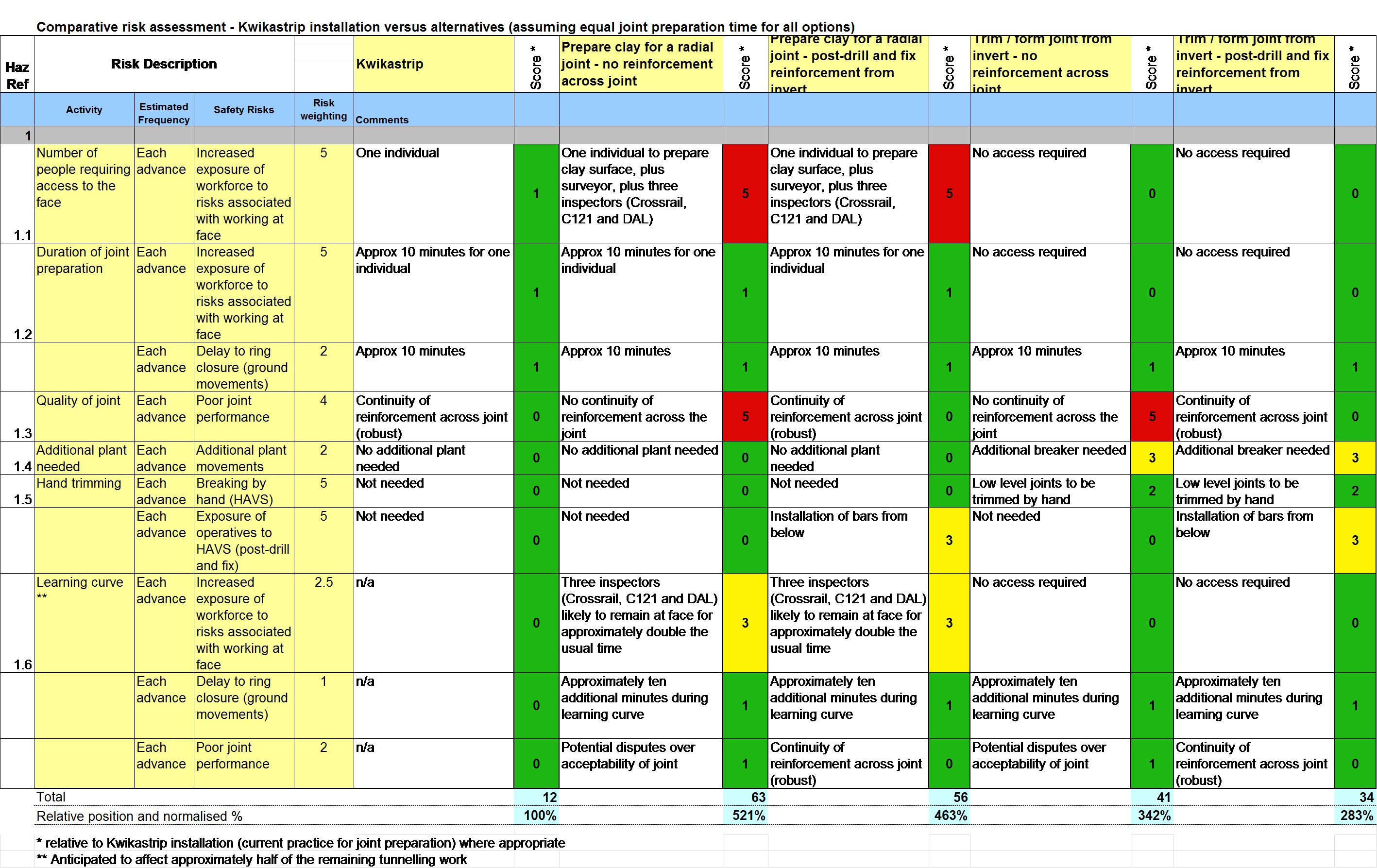
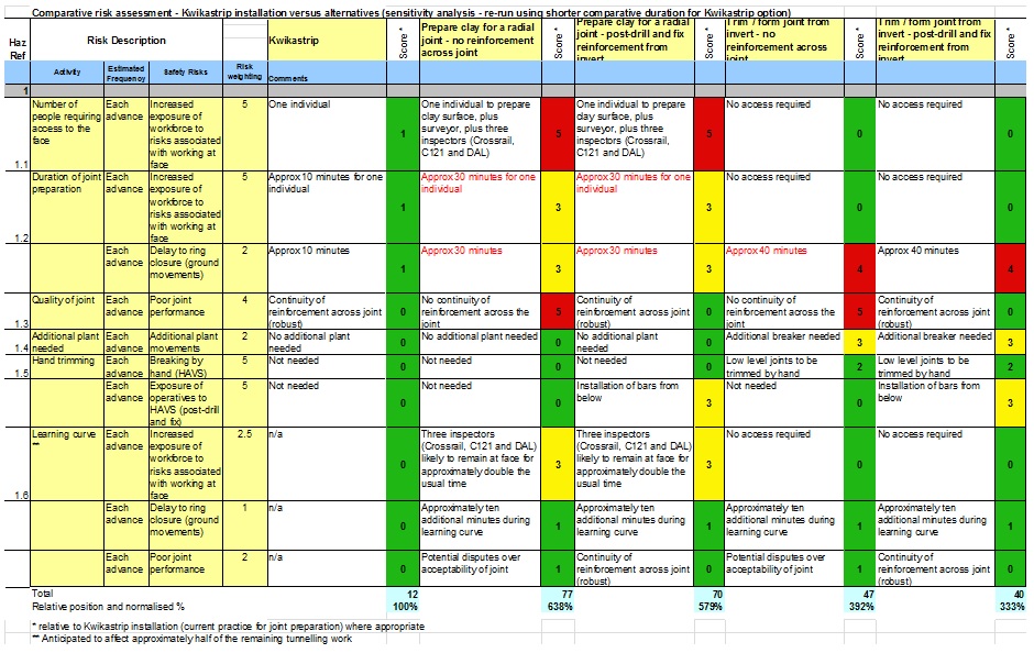
Figure 5 – Comparison between Fisher Street (L) and Stepney Green (R) cavern geometry It was widely acknowledged that longitudinal joint preparation between top heading / bench / invert was a safety-critical aspect to the construction of all SCL tunnels[3] [4]. The project team considered that a Kwikastrip (or similar) joint detail provided the designers with the most robust solution which minimised the residual design risks ALARP. The joint detail at Fisher Street mandated two rows of bars, 12mm diameter, 200mm spacing with a 400mm embedment depth (see Figure 6). For a variety of reasons, this particular detail was not universally specified on Crossrail, and it was recognised this required personnel access to prepare and install the Kwikastrip beneath relatively immature shotcrete. The joint would typically be prepared by a very small number of people, working close to the tunnel wall (not beneath the crown) and only once the exclusion zone had been lifted (minimum shotcrete strength 0.5MPa and minimum 45 minutes after sprayed had finished)[5]. A study was therefore undertaken by C121, the PM team, BFK, DAL and the Crossrail Chief Engineer’s Group to challenge this detail. In particular, to see whether an alternative joint detail could be agreed, which might further reduce personnel access to the face, yet deliver a buildable and robust joint which complied with the designer’s requirements. A comparative risk assessment was therefore undertaken using a range of possible methodologies which might enable safer and quicker joint construction to the required quality standards and design performance requirements. The outcome of this study is included in Appendix A.
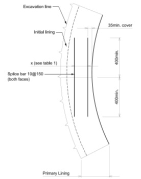
Figure 6 – Standard joint detail with continuity reinforcement (Kwikastrip or similar) The key conclusions were that the use of a Kwikastrip (or similar) joint was the most robust and ALARP solution, and should be mandated by the SCL designer until such time as new equipment may become available. Particular ideas include quick-hitch plant attachments for remote controlled concrete saw-cutting, and remote controlled inspection / measurement devices to assure the standards of workmanship required by the design. Once developed and commercially available, such innovative plant may be capable of providing high quality, assured perpendicular radial joints using remote controlled means without the need for Kwikastrip. As yet, this remains an aspiration but is a clear challenge and opportunity for future development.
Construction
The most significant construction challenges at Fisher Street related to the construction of caverns WBX and EBX, and there were a number of “lessons learned” from WBX which were subsequently deployed in EBX as part of the project’s drive for continuous improvement. These issues are discussed below, together with further refinements which might be applied in the future.
Sequence:
Enlargements WBX and EBX were divided into three sections as described below, each of which was constructed typically using a top heading, bench and then invert (see Figure 7). The top headings were typically 1m long, whilst the bench and inverts were both taken in 2m advances. As a result, the maximum stagger between top heading and ring closure was 5m.
Part 1: enlargement itself, approx. 45m long
Part 2: right hand sidewall, approx. 10m long
Part 3: enlargement of sidewall, also approx. 10m long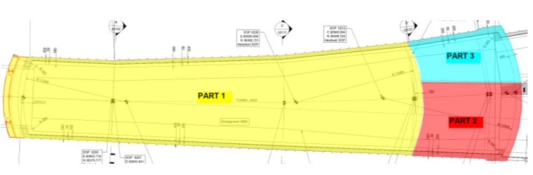
Figure 7 – Plan view of WBX with division into enlargement (Part 1), right hand side with temporary sidewall (Part 2) and enlargement with demolition of sidewall (Part 3) One early refinement instigated by the site team was the omission of the bench for the first 30m of WBX, since the net size of enlargement (from the TBM pilot) was relatively small. This refinement was successfully implemented, resulting in faster ring closure (which assists in reducing settlement) without compromising face stability.
The excavation for WBX commenced by breaking out the precast concrete rings from the temporary (TBM) pilot tunnel using a remote-controlled Brokk (see Figure 8). Two complete rings were demolished, and a temporary SCL flare was later re-excavated using back-excavation to form the permanent headwall collar. The demolition of these rings on WBX caused a degree of damage to the last permanent ring; as a consequence, the starting position for EBX initial breakup was shifted by 10m. This refinement resulted in an additional length of subsequent back-mining, but significantly reduced the damage to the permanent precast rings (see Figure 9).
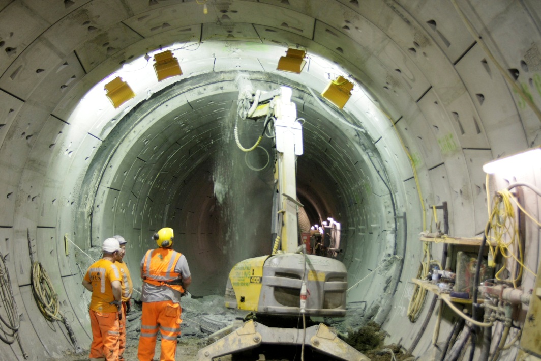
Figure 8 – Remote controlled Brokk being used to demolish precast concrete rings for the initial breakup for WBX 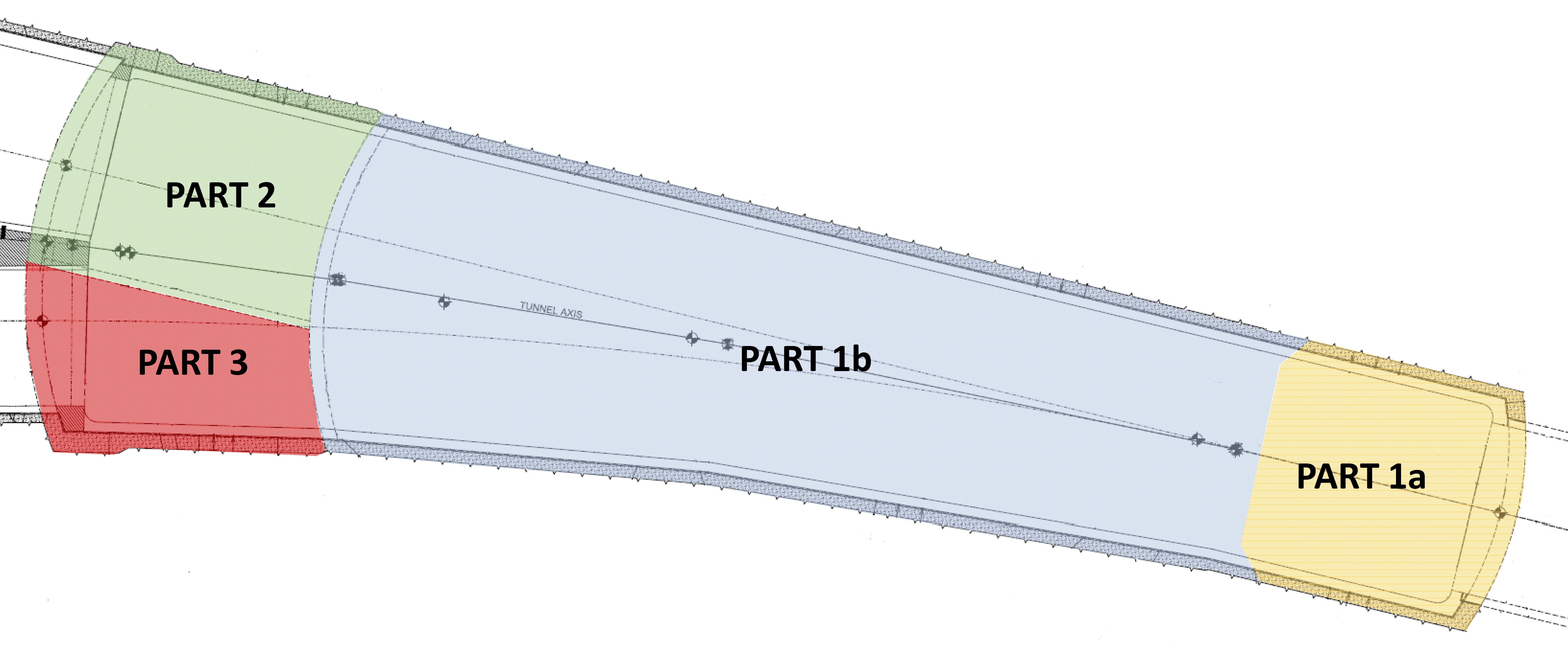
Figure 9 – Enhanced sequence of EBX, with subdivision into parts 1a and 1b to aid logistics and reduce damage to permanent pcc lining Logistics and supply
Fisher Street shaft and intervention adits (IA1 / IA2) (see Figure 1) were used as the primary logistics route to the works, but two key improvements were instigated by the BFK site team.
Firstly, two temporary drop-pipes were sunk to connect the disused Kingsway Tram Tunnel (west of FIS shaft) (KTT) into the crown of both running tunnels. This provided the team with valuable supply point for concrete, both for the SCL works and for the first stage concrete works in the running tunnels (see Figure 10).
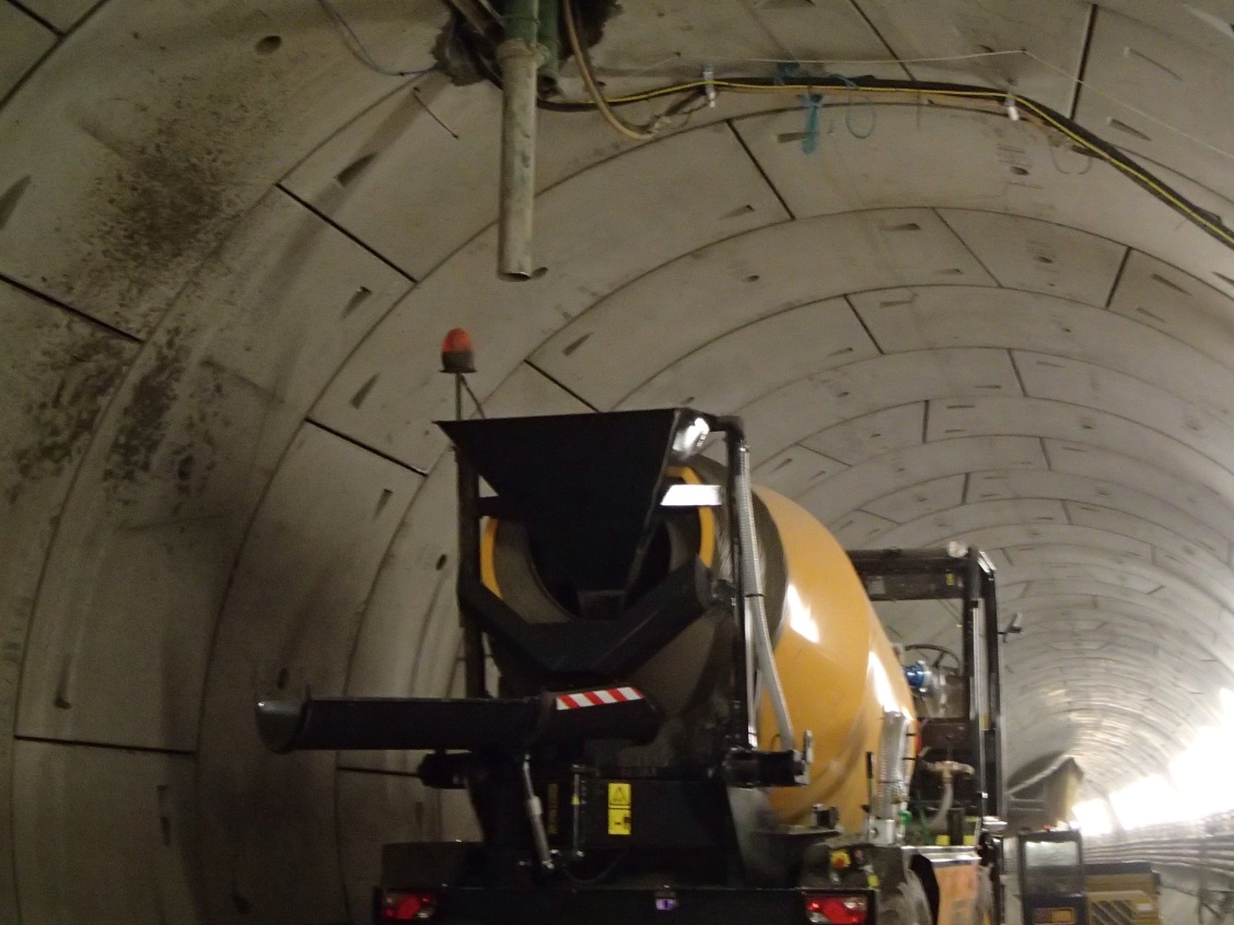
Figure 10 – Temporary concrete drop-pipe connecting KTT to running tunnel, providing the team with significant logistical benefits, reducing demand on Fisher Street main shaft Since the westbound caverns were constructed from west to east, supply from the Fisher Street shaft was simple. However, the eastbound caverns had to be constructed from east to west for safety reasons and to follow the flaring (enlarging) profile, thus requiring the logistics to be supplied from the east. Since Farringdon Station was, in effect, quarantined, the team had to establish a logistics route along the westbound tunnels, through CP5 (which was extremely small and congested) and then back along the eastbound running tunnel (see Figure 11). To improve this logistics route, BFK constructed a temporary concrete supply pipe between the running tunnels approximately 50m westwards of CP5. This was constructed by pipe jacking a 700mm diameter pipe, through which the concrete supply pipes were fed.
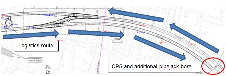
Figure 11 – Plan view showing logistics route through CP5 to supply EBX Both the pipejack and the KTT drop-pipes proved to be of considerable benefit to the project, both in terms of logistics, cost and programme savings.
Geometric complexities: three different alignments through one cavern
The enlargement of WBX and EBX thus entailed the progressive demolition of a precast concrete running tunnel (constructed based on a permanent rail alignment), but with one side of the enlargement following the diverging rail alignment for the crossover. The cavern excavation was therefore constructed based on a third, different alignment, essentially bisecting the other two alignments. The doming of the excavation face both in the vertical and horizontal planes therefore caused a considerable amount of complexity, particularly since the theoretical excavation profile (perpendicular to the third axis), chainages and face doming did not precisely follow the leading edge of the precast concrete rings (see Figure 12). Excavation along the running tunnel axis was not possible since the reinforcement had to be installed perpendicular to the third axis (see Figure 13). This resulted in a significant challenge for the surveying teams, and complexities in fixing the reinforcement in the primary lining.
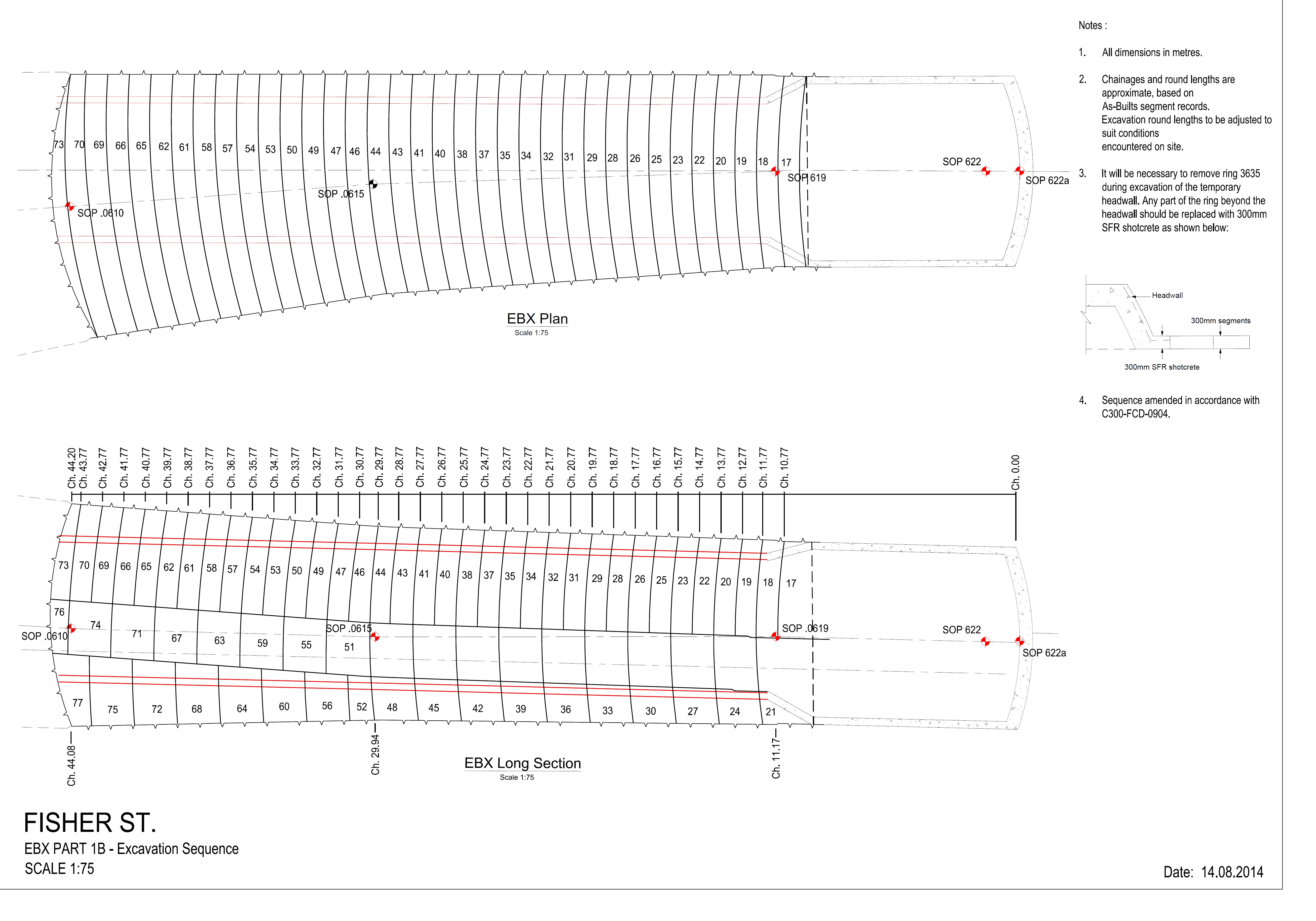
Figure 12 – EBX plan view and long section showing detailed excavation sequence and relationship between three axes, and the interface between circumferential joint on the pcc ring and the SCL advances 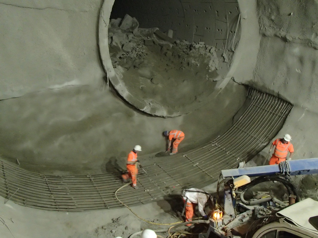
Figure 13 – Fixing invert reinforcement parallel to axis of enlargement (skew to angle of TBM pilot tunnel) This was generally overcome by excavating the face perpendicularly to the enlargement (third) axis, but profiling the right hand side so as to be perpendicular to the precast concrete segments. This could not be fully modelled in 3D, and was thus largely executed using the skill and judgement of the excavator driver and shift surveyor.
Whilst this arrangement was ultimately successful, initial discussions between design, construction and surveying teams indicated the need for a pragmatic approach in the definition of geometry and the expectations in terms of precision.
Constructing joints (top heading & invert) at sidewall drift
Two key issues were critical in relation to the joints, particularly at the crown and invert where the temporary sidewall met the permanent lining:
- Continuity of reinforcement across the joint
- Ensuring that the joint was perpendicular to the primary lining
Reinforcement continuity across the joints was a particular challenge. During the DDR process there was considerable debate over the relative merits of using L-bars, post drill & fix, Kwikastrip or couplers to achieve the required reinforcement continuity.
- According to the original design, L-bars would have been installed in an area of temporary sidewall, and then bent outwards during construction of enlargement (see Figure 14). However, the bars would have been completely covered in shotcrete, and would most likely have been severely damaged during demolition of the sidewall. It was not felt that this was a viable practical solution.
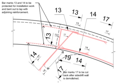
Figure 14 – Original concept of L-bar arrangement, which was subsequently to be bent outwards during enlargement - Post-drilling bars after the enlargement had been excavated (and after the initial sealing layer had been constructed) was also not considered practicable because of the length of embedment required (up to 860mm), the awkward location and geometry of the bars (access required to drill such long bars) and also due to health and safety reasons (working at height, directly under the crown, under the protection of only 75mm of the relatively immature shotcrete “initial sealing layer”).
- Kwikastrip was not practical because the distance between the bars was only 180mm (design required to have 320mm), and the length of legs was only 460mmm whereas the design required 850mm.
- The only safe, practical solution was therefore to use couplers to provide reinforcement continuity at the joints (see Figure 15).
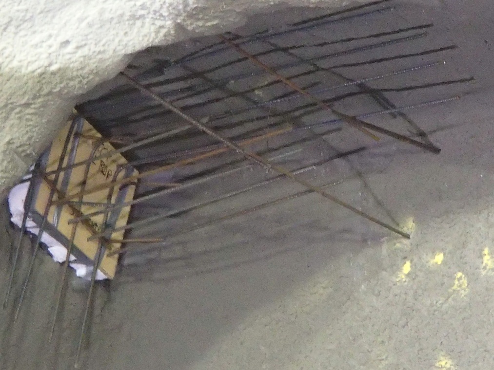
Figure 15 – Photo showing coupler arrangement at joint, with polystyrene and timber joint former The joint in top heading was therefore created by the installation of timber board (to assist with ensuring that the joint was perpendicular to the primary lining) combined with polystyrene to protect the reinforcement. Hyrib was also considered but it was felt that this would have attracted rebound which could then have been extremely difficult to remove. The orientation of the plywood/polystyrene former caused interesting debate, since both options had inherent disadvantages, including steel fibres getting stuck in the polystyrene, etc. and thus increasing the efforts to remove the polystyrene and preparing a high quality joint. On reflection, a sandwich construction (ply-polystyrene-ply) would have been the optimum solution.
Particular challenges also occurred with the fixing of the temporary joint former. With the deletion of the lattice girders (discussed above), there was no longer a convenient method for fixing the joint former. Steel dowels pinned through the initial sealing layer were not permitted for durability reasons, since the primary lining formed part of the permanent works[1]. In the event, additional longitudinal lacer bars were drilled and fixed into the previous advance and face. Whilst this worked adequately, this did increase the likelihood of shadowing. With the benefit of hindsight, a better solution might have been the use of GRP dowels pinned through the initial sealing layer on the outward side of the joint former so that the dowels could be removed during construction of the enlargement.
Geometric control over the placement of this joint former was extremely difficult, not least due to the constantly-changing profile of the excavation. It might have been possible (albeit extremely complex and difficult to control) to provide full 3D geometrical definition of each joint former; however, this would not have mitigated the perhaps larger issue of poor visibility of the joint for the surveyor, excavator driver and nozzleman, which was further exacerbated by the flaring profile (see Figure 16). This joint detail resulted in many NCRs and regular over-excavation, which led to excessive localised shotcrete thickness (typically 700mm rather than 400mm specified). This resulted in slower and more difficult demolition of the sidewall. In summary, the complexities and difficulties of accurately forming such a joint should not be under-estimated by the designer and should thus be avoided by design in the future, if possible. On a practical point, switching to a smaller bucket size for detailed excavation was of some benefit, and the deployment of kinematic integrated profile control systems, already available for plant working above ground, might provide a viable solution to overcome the visibility issues described above.
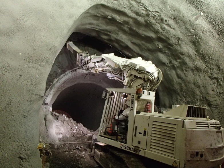
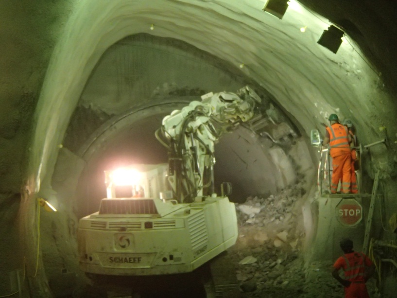
Figure 16 – Poor visibility and severely restricted working space, particularly around top of sidewall joint detail A number of challenges were faced in relation to poor encapsulation of steel reinforcement, particularly around the joint areas. These were mitigated by reducing the pump rate on the spraying plant and reducing the accelerator dosage. Regrettably, this also led to an increase in shotcrete fallouts[6]. One future improvement would be avoiding the use of steel fibre reinforced shotcrete in areas with bar reinforcement or mesh. Encapsulation was also improved by fixing and spraying in of the far face reinforcement, followed by fixing and spraying in of the near face reinforcement. However, the design and reinforcement detailing needs to support this sequence.
Good encapsulation was also significantly hindered by the geometry of the sidewall joint; with limited space and poor visibility, the nozzlemen found it extremely difficult to spray perpendicular to the substrate, with the nozzle at the optimum distance from the lining.
Sidewall demolition sequence
The designer’s original intention was to retain the temporary sidewall until full excavation of Part 3. This was not practical due to concerns over joint quality and, in part, due to BFK’s preferred plant and equipment. The sequencing was therefore refined during the DDR process to allow progressive demolition of the sidewall as excavation of the enlargement proceeded. This was further improved on site by leaving a 500mm stub of sidewall after bulk demolition. The stub was subsequently removed using a combination of milling and percussive breaking, enabling faster production rates, improved quality, more rapid ring closure and thus reduced settlement. This also reduced the risk of forming a non-perpendicular joint.
Fallouts
There were a number of concrete fallouts during the construction of the crossover caverns. The reasons for shotcrete fallouts are not well understood[6] but for this section two particular patterns were apparent during the construction and both were linked to geometry of the profile:
- shallow arch in the crown appears to increase the risk of fallout. Designers should consider this carefully as part of future designs (see Figure 5).
- limited space and awkward geometry of sidewall drift, particularly at the joint positions. This created poor visibility for the nozzleman and meant that the nozzle could not be oriented perpendicular to the substrate due to limited workspace (see Figures 16 and 17). These challenges appeared to result in a higher fallout. This might be overcome by providing a bigger cross section of the sidewall or, in time, a completely automatic spraying system which is not yet commercially available. A marginal improvement could be achieved by deploying additional task lighting to the area.
Further discussion on fallouts is included in King et al[6].
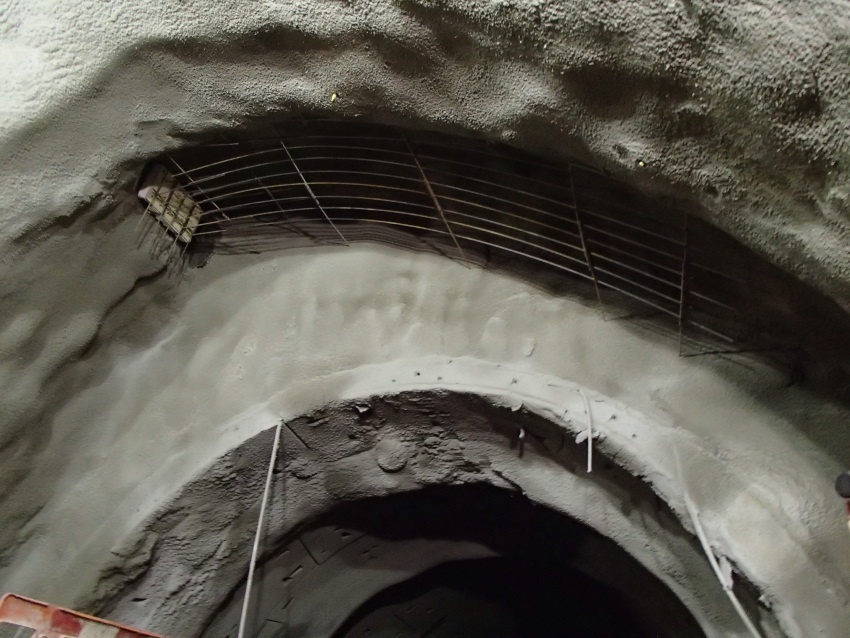
Figure 17 – Top joint of sidewall drift prior to enlargement Other observations for future development
With the benefit of hindsight, it appears that it might have been possible to make further design modifications to combine bench and invert, and / or to completely avoid the complexity of a sidewall drift. The presence of a large diameter precast concrete pilot tunnel has considerable benefits[2], and a comparison is included below between the (offset) permanent headwall detail at the ends of the platform tunnels at both Bond Street and Tottenham Court Road, and the widest part of the WBX/EBX cavern (see Figure 18). There is a striking similarity in the profiles yet, in similar ground conditions, the Fisher Street cavern has had the face subdivided into 6, compared with only 2 at Bond Street and Tottenham Court Road.
It is clear that the Fisher Street caverns were on the lower bound of the size whereupon a sidewall drift should be deployed. In particular, this led to a crown which was possibly too flat, and a significant complexities at the sidewall joints in terms of buildability, reinforcement congestion and reinforcement continuity. This has also had adverse impact in terms of fallouts. On reflection, it seems that it may have been possible to omit the sidewall altogether. This would have had multiple benefits in terms of advance rates, more rapid overall (over whole cross section) ring closure, minimising the number of joints, improving quality and maximising the space for the excavator and spraying plant. However, such a decision would also have been affected by the absence of compensation grouting and the presence of the Lambeth Group below axis.
These observations are not intended as a criticism but as “lessons learned” and suggestions for future enhancement based on the team’s successful, if challenging, completion of the SCL design.
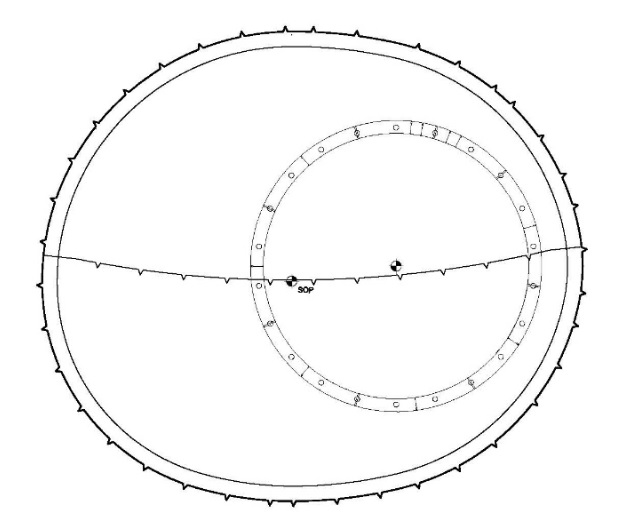

Figure 18 – Comparison between Tottenham Court Road platform tunnel enlargement near permanent headwall (TBM pilot tunnel with top heading / invert) and Fisher Street WBX cavern enlargement (TBM pilot tunnel, single sidewall drift, each gallery with top heading, bench and invert) Surveying / modelling
One of the key challenges for the BFK team was the development of a 3D surveying model (point cloud) which fully defined the geometric requirements of the design based on a set of 2D (PDF) construction drawings. The point cloud was used by the BFK engineers and surveyors to accurately control the excavation and spraying operations. The designer’s 3D model was available for reference purposes only, but it was not considered to be “assured” and therefore could not be used for directly setting out the works. This contractual constraint was a considerable barrier to the effective delivery of the works.
The geometric requirements of the design were extremely complex; the tunnel profile varied constantly in both horizontal and vertical directions and, as the excavation flared, the leading edge of the SCL advances tended to diverge from the leading edge of the precast concrete pilot tunnel, even though the 1m SCL advances notionally “matched” the length of the 1m long temporary pcc rings (see Figure 12).
The Contractor’s team therefore commenced by building their own 3D model from first principles using the 2D PDF drawings. This gave rise to a large number of technical queries, which were augmented by numerous workshops between the design and construction teams. Once almost complete, BFK commissioned 3D printing of the model which had been produced (see Figure 19). This model flagged up a number of remaining discrepancies between the two models (for example, unexpected steps and lips in the profiles), which allowed further refinements and requirements to be instructed by the designer.
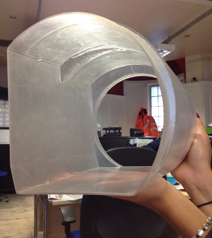
Figure 19 – Photo showing 3D printing model as a visualisation tool Whilst this was an innovative method of overcoming the issue, there are two key “lessons learned” which need to be embraced by the industry, particularly if BIM technology is to be utilised to its full potential.
- Simplicity: whilst the final design was probably quite efficient structurally and from a spaceproofing perspective, it would probably have been much simpler, quicker and cheaper to construct if the profiles had been simplified and standardised. This applies to both the primary and secondary linings. This additional investment in material cost for the reinforcement and concrete would have yielded significant benefits in both direct and indirect cost, and the time required to construct the works. This is not intended as a criticism of the final design, rather a “lessons learned” based on the experience of the team following construction. This was particularly evident in the secondary linings of EB and WB binoculars where rationalisation and simplification would have delivered benefits without compromising the functionality of the completed works.
- Linking design outputs to construction inputs: It should be possible to design and draw such complex structures within a 3D modelling environment and provide a “quality assured” model compatible with the Contractor’s surveying systems, which could be used directly for the setting out of the works (once suitable construction tolerances have been added). Continued reliance upon 2D (PDF) construction drawings will hamper the development and application of BIM. Design and construction contracts need to include suitable provision that the 3D models receive suitable scrutiny and assurance, and that they may be relied upon for the provision of the works. This is considered essential if BIM is to be exploited to its full potential.
Surface settlement
Prior to commencement the designer made settlement predictions generally based on volume loss of 0.5% to 1% for the TBM and 1.5% for the SCL excavations. As mentioned earlier, a number of changes were made to the design post award that had positive benefits for the design and construction including changing the profile, removal of lattice girders and deletion of compensation grouting. The latter meant that there was no compensation grouting for the protection of the sensitive and valuable real estate above the Fisher Street caverns, which were the second largest SCL excavations on Crossrail.
This made the control of ground movement more critical as there were limited options available to provide mitigation. However, as discussed in earlier sections using monitoring data to inform the construction sequence was a key element in the understanding and control of ground movements. All monitoring, both surface and in-tunnel, was reviewed once per day at the SRG meeting. An example of this being achieved successfully was the excavation sequence in WBX where the invert and bench excavation were combined, thus reducing the time to ring closure and thus the associated settlement. However before this decision could be made, settlement data and convergence monitoring in the tunnel were closely monitored to ensure that this change could be safely accommodated without compromising the assured design. Of course it was not only the settlement data that was critical, but also the stability of the excavation. The team instigating a number of measures to mitigate this risk including face stability assessments, a regime of probing ahead and depressurisation drilling, careful control of the excavation and detailed logging of every excavation face.
Figure 20 below details the location of selected critical monitoring points above the crossover. The area had much more monitoring installed than shown here, but it is these points which this paper uses to assess the impact of the tunnelling works at FIS on the surface movements. In particular, these were levelling points installed on buildings directly above the crossover. These buildings were within the influence area of both TBMs and SCL tunnels.
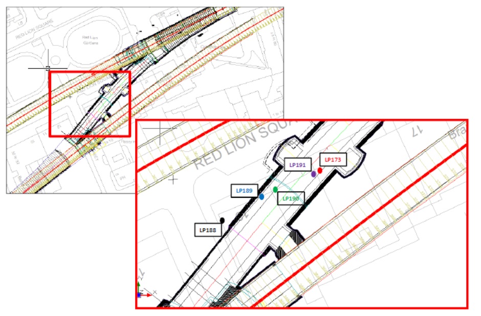
Figure 20 – Plan view showing location of critical surface monitoring points above the crossover In the assessment of the development of ground movements the following stages are considered:
- Passage of the WB and EB TBMs
- Construction of WBX and WB
- Construction of EBX and EB
- Construction of the crossover and the niches and cross passages
The graph below (Figure 21) clearly shows the development of settlement with time above the Fisher Street crossover for each of these stages of the excavation.
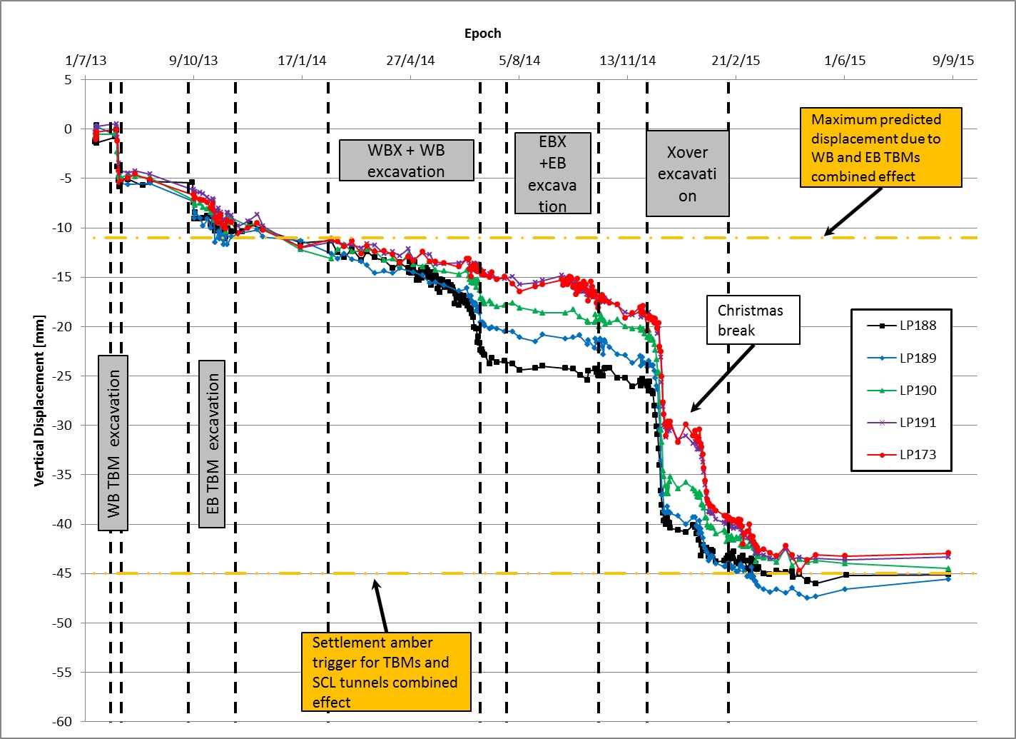
Figure 21 – Time-related settlement in relation to construction activities Initially the passage of the TBMs led to a surface settlement of up to 10mm, which was in line with the predicted movements for the TBMs in this location.
For the analysis of the settlement associated with the remainder of the excavations, there is a difference in the settlement recorded due to the distance of the excavation from some of the points. For example LP188 sees a lot of movement (15mm) during WBX/WB excavation but limited movement (<5mm) during excavation of EBX and EB.
There are a few points of interest in the above graph:
- The settlement recorded for WBX/EB against EBX/EB are quite different, even though they are similar profiles in similar ground conditions. There was up to 10-15mm movement for WBX/WB with only around 5mm for EBX/EB. However the speed of the excavation for EBX was approximately twice as fast as WBX, and is probably a contributory factor in this reduction since the ring closure on EBX/EB would be much quicker. Moreover, the distance between the chosen monitoring points and WBX is slightly less than from EBX, so it was to be expected that the latter would have slightly less influence.
- The magnitude of the movement between the crossover and EBX/WBX was also quite significant. This is a smaller cross section but was the last tunnel completed and also includes the cross passages and niches which will have contributed to the recorded movement. This section was also undertaken with traditional top heading and combined invert/bench with no pilot unlike the other sections at FIS. Note that the stable section in the crossover monitoring data is during the 2 week shutdown for Christmas where a safe stop procedure was installed and hence negligible settlement occurred during this period.
- The overall maximum settlement recorded at the surface for the FIS crossover area was approximately 45mm which is again in line with the maximum predicted settlement of approximately 49mm.
- As showed in Figure 22 approx.30%-40% of the settlement was developed in advance of the arrival of the tunnel SCL front. This shows the effectiveness of the staged excavation and adequate face support for the control of settlements in the longitudinal direction. Note that the settlements have been normalised on the maximum settlement on each measurement point.
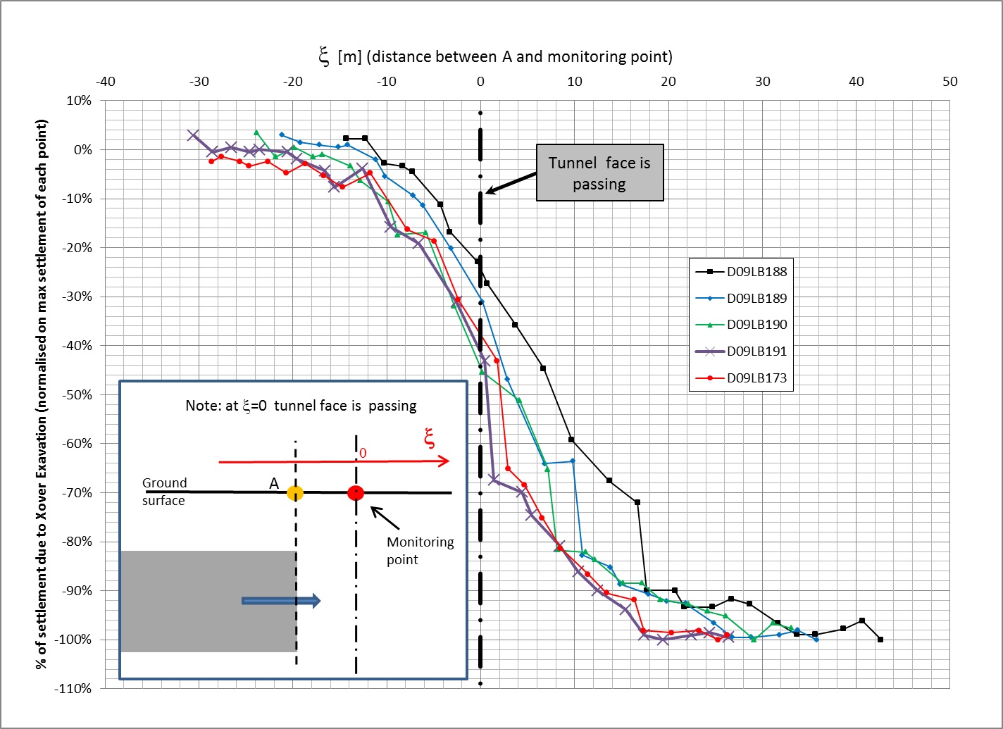
Figure 22 – % of surface settlements developed as a result of the crossover (only) excavation in respect of relative plane distance between tunnel front and monitoring points. Settlements are normalised on the maximum settlement measured on each point. The figure below (Figure 23) details the settlement contour development at Fisher Street. It is clear that the settlement peaks are at the crossover and WBX and EBX, which is as expected given the relative size of the excavations in this area.
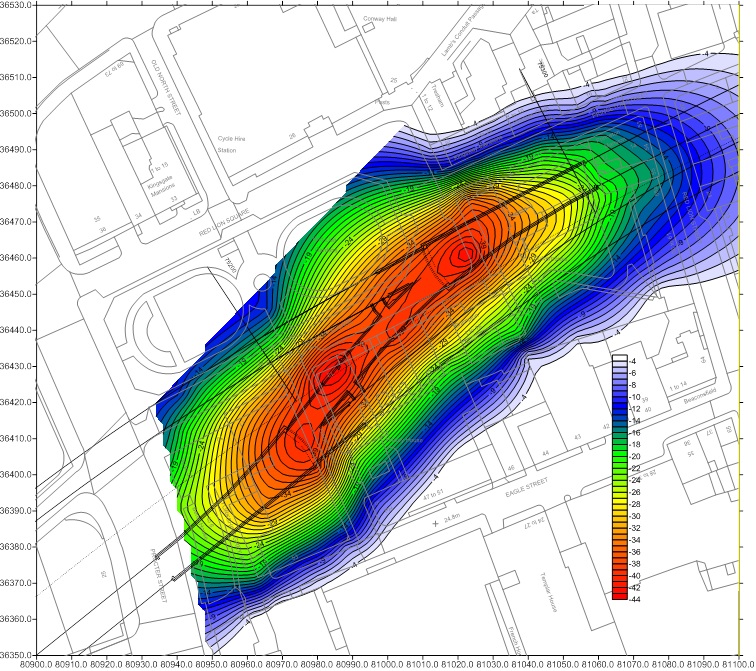
Figure 23 – Contours of surface settlement (mm) due TBMs and SCL excavations in Fisher Street crossover, excluding CP2 and niches Note that this assessment only considers settlement and does not consider slopes or strains on buildings.
The above is only a snapshot of the vast array of time-related settlement data recorded at Fisher Street during each stage of the works. This snapshot has been used in this paper to demonstrate that the construction of large SCL tunnels in urban environments can be undertaken safely and without adverse impact to properties without the need for installation of pre-mitigation measures such as compensation grouting. However this does require good construction control; monitoring to ensure that settlement limits are not being exceeded; effective communication between operatives and engineering teams and the ability to adjust excavation methodology to minimise settlement if required and, if necessary, to deploy toolbox measures.
Lessons learned and conclusions
The construction of the Fisher Street Crossover was one of the most complicated sections of tunnelling on the C300/410 project and possibly even across the project. The design of the crossover required an overall span on approximately 15m. In central London with the value of the surface infrastructure and buildings this was always going to be a challenge. However by the collaboration of all parties in the design and construction process it was possible to achieve the safe construction of the crossover with no adverse impact on surface buildings and without the use of compensation grouting as a control measure. This was achieved through a thorough understanding of the design and construction process and using previous experience and monitoring data to enable positive changes to be implemented.
There are many lessons to be learned from this collaborative approach and these include:
- Compensation grouting is not always necessary for the construction of large SCL excavations in London Clay in an urban environment. Careful control during construction and changes to the excavation sequence can assist in the control of ground movements. It is vital however that there is an adequate monitoring system in place that can be used to react to changing conditions.
- The use of sidewall drifts should be reviewed and their necessity reconsidered for cross sections of this size and shape. It is likely that construction of chambers of this size could be completed with a pilot tunnel advance (TBM or SCL) rather than introducing a sidewall drift and the additional complications of joints and joint reinforcement. Where a sidewall drift cannot be avoided the design should consider more favourable geometry to make the joints simpler and also reduce the reinforcement required.
- The construction of the crossover at FIS without any lattice girders demonstrates that it is feasible with good construction control and surveying techniques to construct complex geometries. The removal of the lattice girders has a positive benefit in terms of safety and the access required beneath recently applied sprayed concrete and with the advance of modern survey techniques and the use of 3D models it is feasible to control the profile to a similar accuracy. Notwithstanding this efforts should be made in the design to simplify the geometry to ease setting out of constantly changing geometries as it introduces additional complications to the process.
- Generally for SCL tunnels where there are longitudinal joints the use of reinforcement across the joint such as Kwikastrip should be mandated until such time as there is equipment available that will allow a perpendicular joint by remote control means and remove the requirement for personnel access to complete the joint.
Finally it is worth recording that the construction of Fisher Street Crossover and the complex geometry inherent within it was made much simpler for the construction and surveying teams with the use of 3D printing and 3D visualisation techniques to achieve alignment between the designer’s requirements and the Contractor’s surveying systems. This should be introduced much earlier in the process for tunnels such as this where there is constantly changing profiles and as the technology develops in these areas it should become an integral part of the design process.
References
[1] Thomas Telford and Crossrail (2015). “Delivering a Safe Integrated SCL design: the challenges and successes of Crossrail Contract C300/C410”. St.John, A., Pickett, A., Kendall, A., Potts, V., McGirr, D. ISBN 978-0-7277-6078-4 pp331.
[2] ITA and WTC (2015). “Use TBM pilot tunnels for large diameter SCL caverns, Crossrail C300/C410”. St.John, A., Potts, V., Perkins, O., Balogh, Zs. Proceedings of the World Tunnel Congress 2015 “Promoting Tunnelling in South East European Region”. ISBN 978-953-55728-5-5 pp734.
[3] HSE (1996). “Safety of New Austrian Tunnelling Method (NATM) Tunnels: a review of sprayed concrete lined tunnels with particular reference to London clay”.
[4] HSE (2000). “The collapse of NATM tunnels at Heathrow Airport: A report on the investigation by the Health and Safety Executive into the collapse of New Austrian Tunnelling Method (NATM) tunnels at the Central Terminal Area of Heathrow Airport on 20/21 October 1994”.
[5] “Best Practice Guide: SCL Exclusion Zone Management” (available via the British Tunnelling Society (https://britishtunnelling.org.uk)
[6] “Sprayed Concrete Lining Falls and Exclusion Zone Management”, King, M., St.John A., Brown, D., Comins, J. Crossrail Learning Legacy
Appendix A: Kwikastrip comparative risk assessment
-
Authors

Adrian St.John, BEng (Hons) Eur Ing FICE CEng - BAM Ferrovial Kier
Adrian St.John is a Fellow of the Institution of Civil Engineers and a Supervising Civil Engineer. He has spent most of his 24 year career working on major infrastructure and tunnelling projects in the UK and overseas, including the Brighton Stormwater tunnel and High Speed 1 at St Pancras. He spent 6 years as Chief Engineer for BFK Joint Venture who were the main contractor on Crossrail contracts C300, C410 and C435, and is the Design Director for Carillion Eiffage Kier (CEK) Joint Venture bidding for the forthcoming HS2 main civil works.

Damian McGirr BEng (Hons) MICE CEng - Donaldson Associates Ltd
Donaldson Associates Ltd
