Design of Crossrail Farringdon Station – from an Engineers Perspective
Document
type: Technical Paper
Author:
Ghanshyam Kumar BEng MTech MEng CEng MIStructE, David Sharples BSc(Hons) CEng MICE, ICE Publishing
Publication
Date: 07/09/2015
-
Read the full document
Notation
BFKJV BAM Ferrovial Kier Joint Venture
CRL Crossrail Ltd
ETH East Ticket Hall
AOD Above Ordinance Datum
ATD Above Tunnel Datum
C121 Contract for design of tunnels lined with sprayed concrete (Mott MacDonald)
C122 Contract for the design of bored tunnels and for the assessment, control and mitigation of ground (Arup Atkins JV)
C136 Contract for the design of Farringdon Station (URS/Scott Wilson)
C430 Contract for the construction of Advanced Works at Farringdon Station
C435 Contract for the construction of the Main Works at Farringdon Station (BFKJV)
CEDS Crossrail Civil Engineering Design Standard
EB Eastbound
EWMA Early Works Managing Agent.
FDC Framework Design Consultant,
FE Finite Element
FFL Finished Floor Level
FRP Fibre reinforced plastic
LOD Limit of Deviation
LUL London Underground Limited
NR Network Rail
O&M Operations and Maintenance
OSD Oversite Development
SSL Structural Slab Level
TBM Tunnel Boring Machine
TfL Transport for London
TLP Thameslink Project
VE Value Engineering
VM Value Management
WB Westbound
WTH West Ticket HallIntroduction
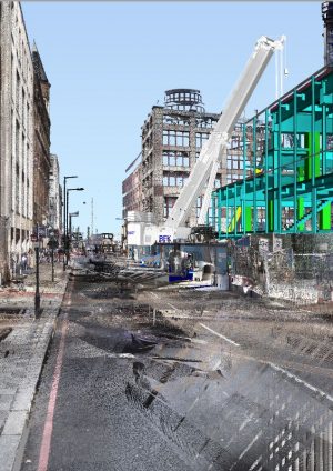
Crossrail Central includes 21km of new twin bore tunnels through central London and the construction of eight new underground stations, plus two new surface stations (see Figure 1). Farringdon is one of the key interchange stations of the Crossrail network. Upon completion, over 140 trains per hour will be passing through the Farringdon interchange when it becomes a link between Thameslink, Crossrail and London Underground services. It will be the only station from which passengers will be able to access all three networks. Farringdon will become one of Britain’s busiest train stations, and will be a key link in bringing passengers from outer London to the business hubs in the City and Canary Wharf. Situated at the intersection of a new east-west (Crossrail) and north-south (Thameslink) axis (see Figure 2), it will be possible to directly connect with three of London’s five airports.
The purpose of this paper is to describe a number of key design features of the underground interchange station at Farringdon currently under construction on constrained sites in central London adjacent to historic buildings.
This paper:
- outlines some of the key design issues
- describes the location and constraints of the station
- explains how the station addresses particular key design issues
- demonstrates how the design was impacted and modified by construction issues
- establishes how the solutions adopted are both appropriate and cost-effective
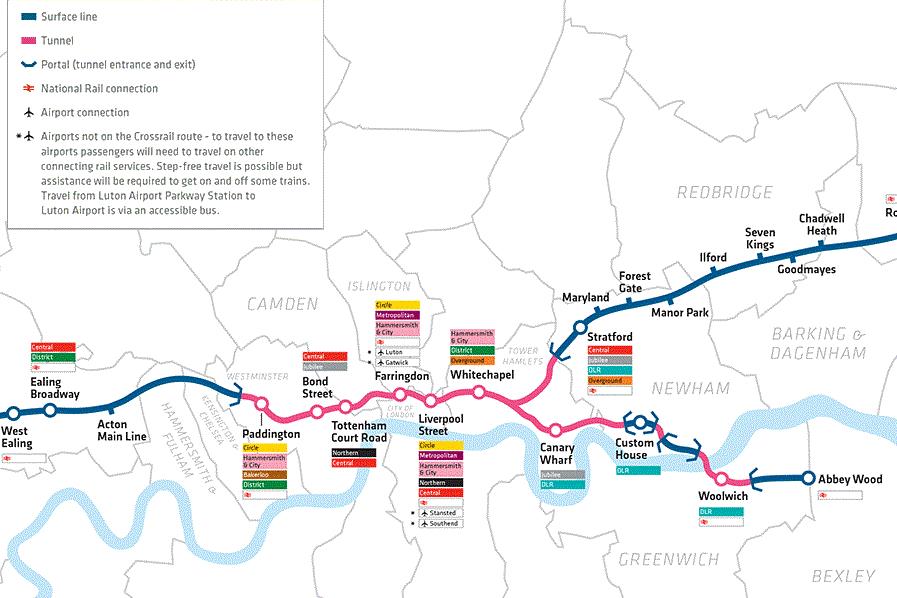
Figure 1 – Crossrail central stations
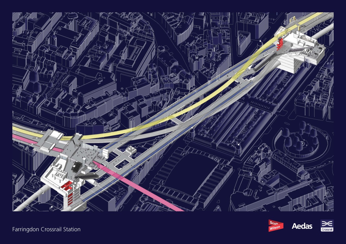
Figure 2 – The Farringdon Crossrail Station
The Station and tunnels works included within Farringdon main works contract C435 are primarily designed by Framework Design Consultants (FDCs) C136 (East and West Entrances and platform structures), C121 (Sprayed Concrete Lining tunnels) and C122 (bored tunnels). The C136 scope of work (see Figure 3) includes:
- The Western Entrance, which completes the Ticket Hall being constructed by the Thameslink Project (TLP) by providing escalator access to Thameslink Platform 4 and to the Crossrail Platforms
- The Eastern Entrance which comprises the East Ticket Hall (ETH), access to the Crossrail Platforms and works to 33-37 Charterhouse Square and Barbican PRM bridge link.
- Platform structures within the SCL platform tunnels, cross-passages and escalator shafts
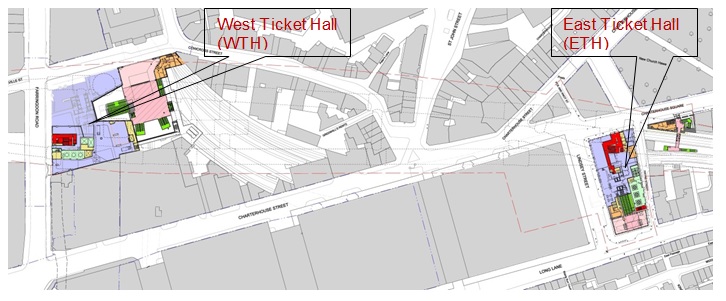
Figure 3 – The Farringdon Crossrail Station site
KEY DESIGN ISSUES
There are various factors that are considered in the design process. However, for the purpose of this paper, the relevant factors are:
- Adjacent existing structures / urban context
- Rail infrastructure connections
- Over site developments
- Integration with tunnelling works
- Ground conditions
- Form of wall construction
- Sequence of construction
- Spaceproofing
The final design of the station is driven by safety, buildability, physical constraints and the need to provide a station appropriate to its location and historical setting. The key design objective has been to provide the travelling public with an excellent passenger experience while providing Crossrail with a design that offers value for money and that can be built safely within the overall Crossrail programme.
Adjacent Existing Structures / Urban Context
The station is to be constructed in densely populated areas on restricted sites and adjacent to listed buildings. Limiting ground movements is a key to minimising the risk of damage to adjacent properties, utilities and infrastructure. This is particularly important for safety-critical items such as certain utilities, London Underground or Network Rail lines, as well as for historical structures.
Rail Infrastructure Connections
Farringdon is located centrally in the heart of London. Apart from providing links to the Circle, Hammersmith & City and Metropolitan lines (LU), it also forms a major interchange with Thameslink – the only other cross-London mainline railway. On completion, Farringdon Station will provide direct rail links to three of London’s five airports.
Over site Developments (OSDs)
Part of the funding for Crossrail is derived from commercial OSDs, which also play an important role in re-establishing the built environment. At Farringdon there are two OSDs, one above the West Ticket Hall (WTH) and one above the East Ticket Hall (ETH). Both the sites will rely on the subsequent OSDs for their full integration into the urban settings.
Integration with Tunnelling Works
One of the key design considerations for Farringdon is the way it integrates with the tunnelling works – both the permanent structural connections and the construction phase (including the dismantling & removal of the Tunnel Boring Machines (TBMs)).
The station platforms will be typically constructed as mined tunnels using Sprayed Concrete Lining (SCL) construction techniques. The choice of construction methodology that was taken forward depended on the alignment of the tunnels and the depth of construction. The depth from existing road to the top of rail level varies between 27m to 32m.
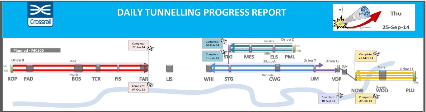
Figure 4 – Tunnelling progress [1] (Sept 2014)
This station is the termination point for both X and Y drives (i.e. 4 TBMs) and has to accommodate their arrival, decommissioning and removal (see Figure 4). Two of these twin-bore tunnels (X- and Y-Drives) affect the construction of Farringdon Station:
- The X-Drive (6.85 km long): Two TBM’s named Phyllis (WB) and Ada (EB) were launched from Royal Oak portal to the west of Paddington Station on 03 May 2012 and 17 August 2012 respectively, and proceeded in an easterly direction passing through Paddington, Bond Street and Tottenham Court Road Stations. Both of these TBM’s completed their journey on 07 October 2013 and 24 January 2014 respectively. The WB TBM passed through the square shaft and formed a pilot tunnel before being turned off-line and buried outside the ETH. Similarly, EB TBM passed through the circular shaft and was used to form a pilot tunnel for the platform enlargement before being turned off-line and buried.
- The Y-Drive (8.3 km long): Two TBM’s named Elizabeth and Victoria were launched from Limmo shaft in east London on 10 Nov 2012 and 25 Nov 2012 respectively and proceeded in a westerly direction which passes through Canary Wharf, Whitechapel and Liverpool Stations. The Expected arrival date for Y-drive TBM’s at the Farringdon is in Feb and March 2015 respectively. Both of these TBM’s will be dismantled, stripped and cut up for removal
Ground Conditions
At Farringdon, the ground is very complex and heavily faulted, with London Clay overlying Lambeth Group and Thanet Sands (see Figure 5). Although, in terms of ground water levels, the site is under-drained at depth, there are perched water tables and water-bearing gravels which create problems for the construction of mined SCL tunnels [2]. These ground conditions have had a major impact on the tunnelling strategy and thus a direct impact on the size, location and sequence of construction of the shafts.
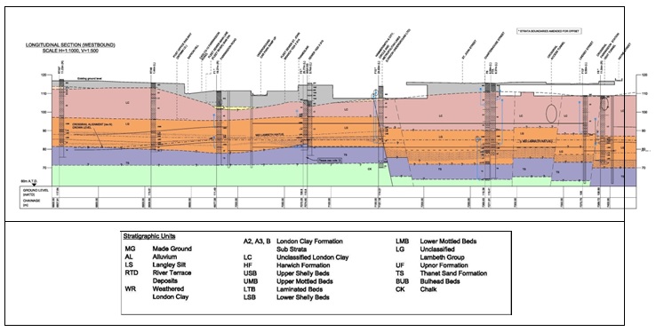
Figure 5 – Geological Long Section through Westbound tunnel [3]
Wall Construction
Deep basement construction is a feature of most Crossrail Central stations, whether in the form of a single cut-and-cover box or a series of discrete shafts & boxes. There is no opportunity to construct a cut-and-cover box as Farringdon is split between two sites (the West Ticket Hall [WTH] site and the East Ticket Hall [ETH] site) which are over 300m apart (Figure 3). While several methods of construction exist, perimeter walls are typically diaphragm walled panel construction, secant or contiguous bored-pile walls.
Although diaphragm-walled construction can offer considerable benefit, the size and type of plant means that it is not suitable for all sites. Diaphragm walling is inherently stiffer than a secant bored pile wall of the same overall thickness. This greater stiffness leads to smaller wall deflections and hence lower ground movements during excavation. However, the size of plant required to construct the panels and to install the reinforcement can be very large. This combined with the need for bentonite storage, means that diaphragm walling is better suited to large sites with good access, and to wall layouts that are reasonably rectilinear.
The four shafts at Farringdon are irregular in shape, and are of different sizes and depths. Access to the piling platforms, several metres below road level, is difficult. That and the size of the sites and their proximity to the rail infrastructure meant that diaphragm walled construction was considered inappropriate – leading to the choice of secant bored-pile wall construction.
Sequence of Construction
The sequence & method of construction for shafts and underground boxes is usually described as either “bottom-up” or “top-down”. “Bottom-up” construction is when temporary propping (e.g. – steel frames or temporary anchors) is used to support the perimeter walls as excavation proceeds down to the bottom. The bottom level slabs are therefore constructed first and the forthcoming levels are constructed progressively upwards.
“Top-down” construction is when the upper level is cast first, and the lower levels are constructed progressively as excavation proceeds. The slabs prop the perimeter walls as excavation proceeds and act as both permanent and temporary work props. Generally top-down construction is better at controlling ground movements. The top slab (which is cast first) can provide useful layout areas on congested sites and/or allow road access to be reinstated. While time to complete all of the permanent works can be similar for either method, the time to reach the base of the excavation using temporary steel props in bottom-up construction is usually quicker. While ETH trapezoidal and WTH circular shafts are constructed “top down”, all other shafts are constructed “bottom up”.
Spaceproofing
The layout and configuration of a railway station has to respond to a complex range of requirements and constraints. For deep underground stations, space-proofing is of particular importance. In addition to passenger flows, vertical circulation and associated space requirements, one of the key considerations is the space-proofing associated with tunnel ventilation, service risers, means of escape and fire-fighting access. Tunnel ventilation, in particular, requires risers with large cross-sectional areas and with a limited number of bends – large fans requiring access for maintenance, repair and replacement.
STATION DESIGN
Farringdon Crossrail Station is located in an area of London with a rich history and were formerly occupied by buildings which have been demolished to allow construction of the ticket halls, shafts etc. to take place. Both ETH & WTH sites are surrounded by roads, railways and structures, with original ground level typically 4 to 6m below road level. The two sites are roughly rectangular and their overall dimensions are approximately 70m x 32m and 65m x 48m respectively. Both ticket hall structures have been designed to accommodate vertical loads and stability loads from the proposed over site developments, as well as making provision for ground level entrances, retail frontages, lift cores, connections to utilities etc. At the WTH, the recently constructed Thameslink Ticket Hall has been designed to accommodate the future Crossrail station construction and to form an integrated Crossrail / Thameslink ticket hall and interchange.
Platform Construction
The ground at Farringdon is complex and heavily faulted, and the water-bearing gravels create extremely challenging conditions for the construction of the platform tunnels. It was established early on in the design process [4] that the platforms should be formed by SCL enlargements to lined pilot tunnels constructed using TBMs. The original intention was to have a mini TBM which would form the pilot platform tunnels at Farringdon that would then be enlarged using SCL techniques. Subsequent Value Engineering based on new geotechnical information concluded that the pilot tunnels could be formed using the larger main running tunnel sized TBMs. The pilot tunnel allows water-bearing channels to be depressurised via wells drilled out from the pilot tunnel, greatly reducing the risk of face collapse during the subsequent SCL enlargement works. Figure 6 shows progress of station tunnelling works by Sept 2014. Figure 7 shows EB platform tunnel (PTE) enlargement.
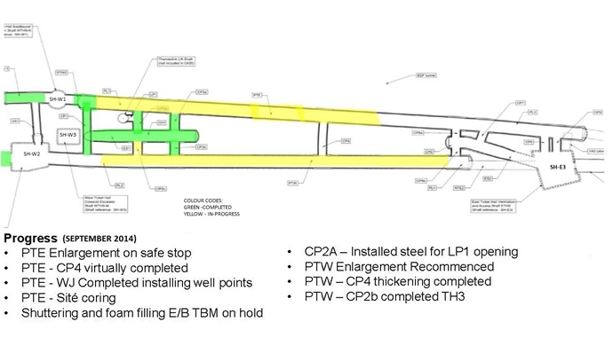 Figure 6 – Progress of SCL tunnelling works[5] [6]
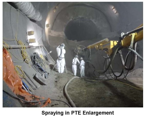
Figure 7 – SCL enlargement of EB Platform Tunnel[5]
Interface with over site development (OSD)
At both the WTH and ETH sites, the new ticket hall structures and their foundations are designed to support future oversite developments. Both ticket halls incorporate stub columns and a crash deck to allow construction at a future date. The Crossrail stations therefore do not form completed architectural entities but rely on the subsequent OSDs to re-establish the urban setting (see Figure 8).
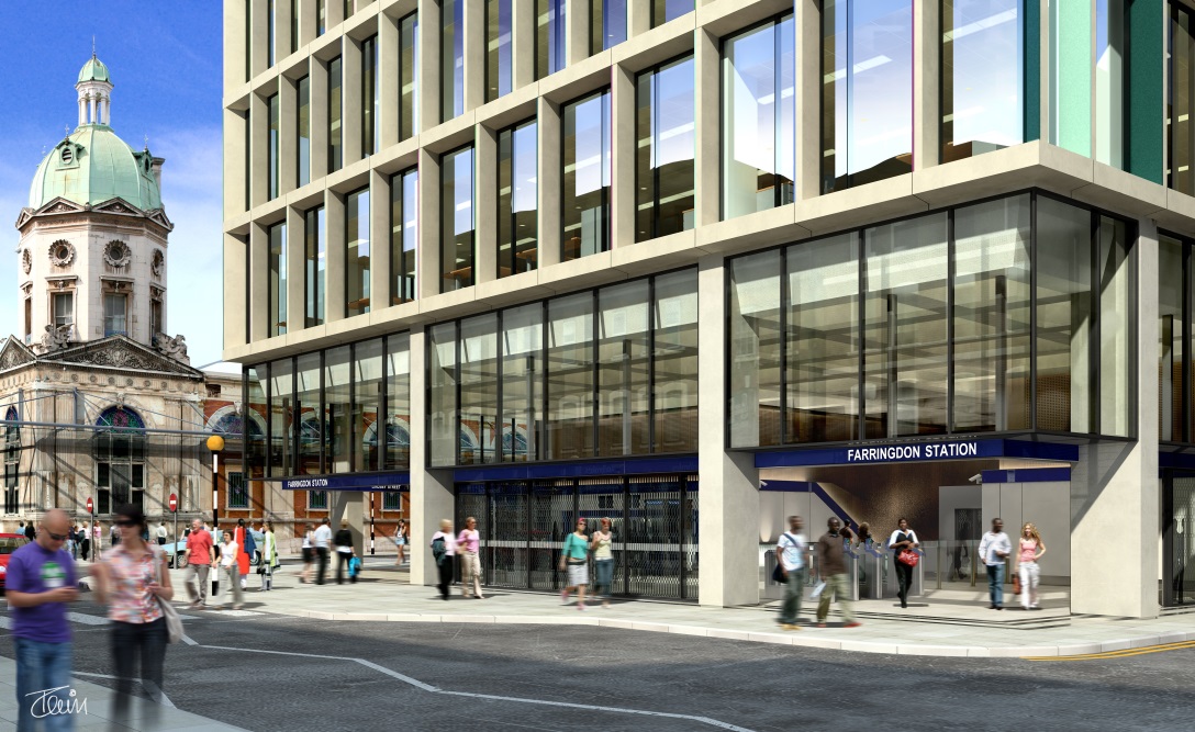
Figure 8 – Farringdon Station (East Entrance)
WEST TICKET HALL (WTH)
There are three shafts at the WTH (see Figure 9), and their design and method of construction varies depending on their function.
- SH-W1 is a circular shaft constructed “semi-top-down”. In other words, part of the permanent structure (the circular waling beams) acts as temporary works as the shaft is constructed top-down. Once the tunnelling has been completed, the lining walls and the remainder of the slabs are constructed from bottom up.
- SH-W2 is a large shaft, approximately rectangular on plan (size 25m x 21m) and is constructed “bottom-up”. The shaft is propped with temporary steel frames at several levels as it is excavated, but the permanent works (i.e. the concrete walls and slabs) are constructed from the bottom up.
- SH-W3 is a rectangular shaft / box structure which is also constructed “bottom-up”. It is significantly shallower than the other two shafts as it does not extend down to track level and essentially acts as work site from which the escalator barrel (ES1) can be constructed.
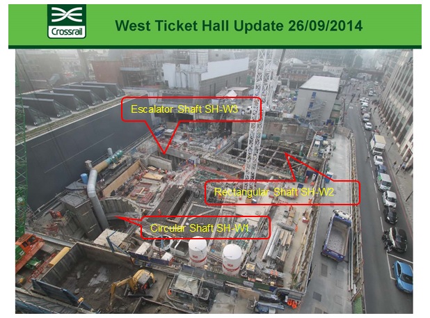
Figure 9 – West Ticket Hall site (Sept 2014)[5]
Circular shaft (SH-W1) on the eastbound tunnel
Subsequently, six levels of intermediate slabs generally 600mm thick will be cast integral with the 400mm thick lining wall and circular waling beams through reinforcement couplers cast into ring beams. The 2.0m deep base slab of the shaft is constructed in stages to allow for the TBM to pass through at a lower level. The shaft was constructed by C430 contractors as Advanced Works to allow for the construction of the stub tunnel prior to the arrival of the EB TBM. In order to connect to the stub tunnel, two openings in the shaft are formed using stitch drilling technique. In the permanent condition it houses a service riser and maintenance stairs providing emergency access to platforms and tunnels.
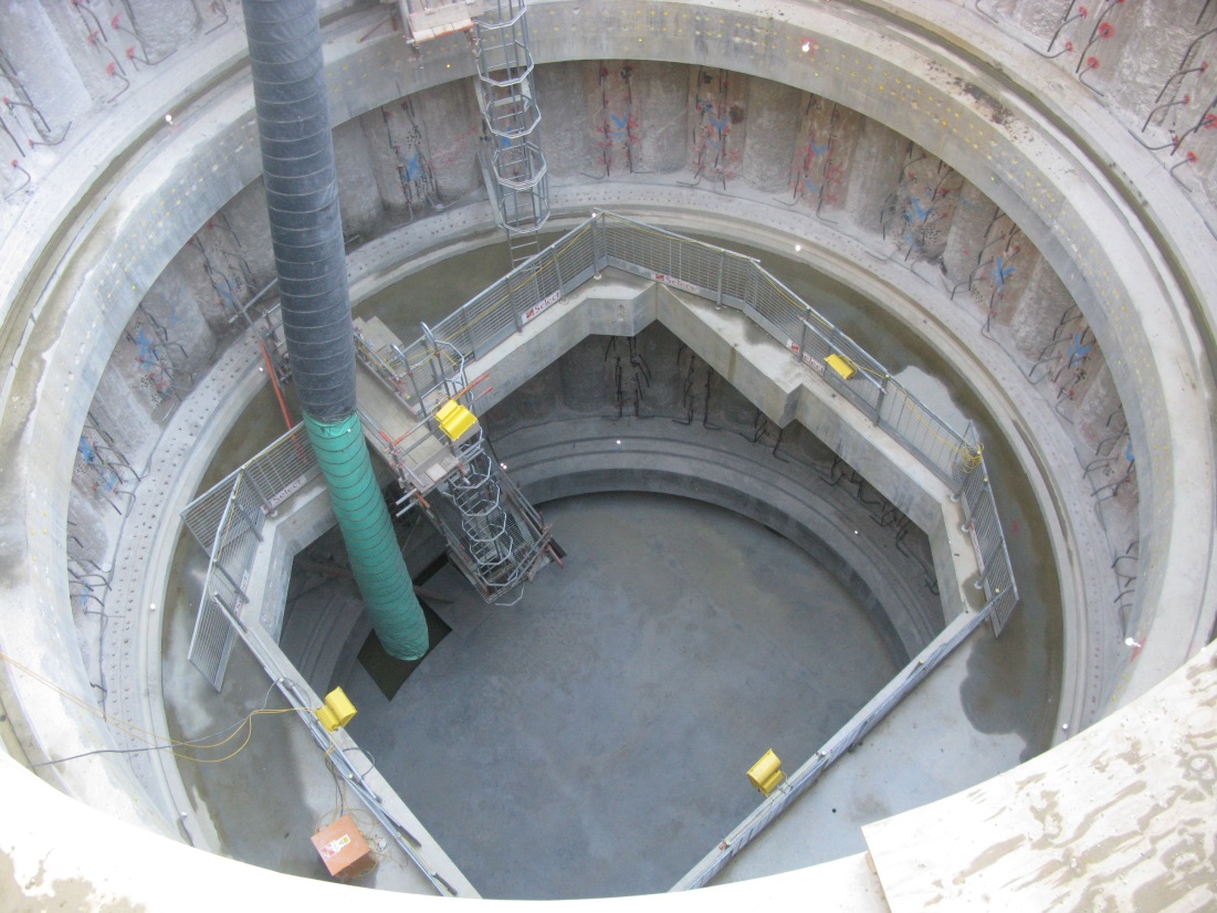
Figure 10 – Circular Shaft SH-W1 photographed in November 2012
Rectangular shaft (SH-W2) on the westbound tunnel
This shaft provides provision for tunnel ventilation, service risers and emergency means of escape. It was necessary to excavate the shaft quickly to allow the westbound X-Drive TBM to pass through. The shaft is adjacent to Farringdon Road, which contains major services. The need to excavate the shaft rapidly has dictated the use of bottom-up construction, but ground movements have been kept within specified limits by using stiff steel temporary frames at close centres.
Escalator Shaft:
This (15m x 11m) shaft is constructed with one level of temporary props and will be built “bottom-up”. Its primary function is to facilitate the construction of an inclined SCL escalator barrel.
Over Site Development
The “collaborative” WTH OSD required close collaboration with the developer and their professional team to agree column & core locations and also load imposed on the station structure from the over site development. The presence of existing piles at the WTH from the demolished building and the area sterilised by the future tunnels imposes severe restrictions on the location of new piles. The vertical loads from the OSD are carried by a combination of the 2.1m diameter foundation piles and the three shafts. Some piles are sleeved to avoid load transfer from the piles to the tunnels and/or to reduce the impact of negative skin friction. A deep raft slab, together with a series of transfer structures, transfer superstructure loads to the foundations.
EAST TICKET HALL (ETH)
A two-storey basement over the south half of the site houses M&E plant, while the north half of the site is occupied by a large deep trapezoidal shaft (SH-E3) measuring 30mx25m, which extends 35m below road level. A 3-D internal view of the ETH is shown in Figure 11.
Its plan size is dictated by the need to accommodate tunnel ventilation, service risers, plant rooms, vertical transportation (two escalators and an inclined lift) and emergency means of escape. Space-proofing requirements have meant that the shaft extends to the site boundary on three sides.
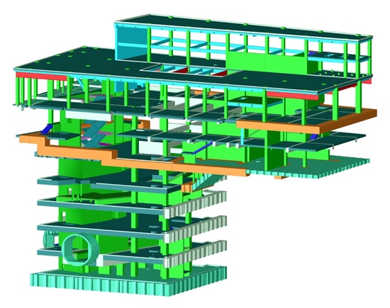
Figure 11 – ETH 3-D internal view (perimeter walls removed for clarity)
The trapezoidal shaft is constructed using hard/soft secant piles installed from the Moorgate Spur level (Level -2). Secondary (male) piles are 1500mm in diameter. Toe level of the wall will be at approximately 66.0m.
The shaft is to be penetrated by, the westbound running tunnel (twice), escalator barrel ES2 from the Crossrail platforms, two cross passages and a ventilation adit from the eastbound Crossrail platform. Due to such a large number of openings on three sides of the shaft, vertical and horizontal loads are transferred through a complex mechanism utilizing combined stiffness and strength of secant piles and the lining wall. At many locations, lining walls act as a deep beam and carries loads across the openings. Lining walls are connected to the secant pile wall through drilled-in steel reinforcement.
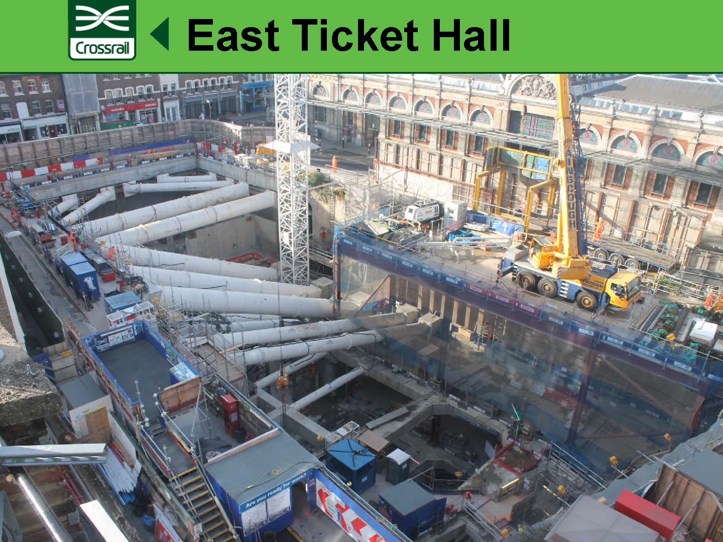
Figure 12 – ETH: Site status (September 2014)[5]
The design takes account of the construction tolerances required for secant piling, permanent concrete lining wall, drained cavity and inner lining block wall for space proofing. Like all other shafts, he concrete lining walls are designed to resist groundwater pressures and are also used to transfer vertical loads around openings in the secant pile wall.
The shaft is arranged on six floors commencing at basement level -2 down to the base slab at sub-platform level -7. Internal floors within the shaft will be of reinforced concrete construction generally 1.0m thick and supported at the perimeter by the secant piles and internally by columns and walls constructed off a 2.5m thick slab at the base of the shaft. The base slab also resists the upward loads due to long-term hydrostatic pressures and soil heave.
“Top-down” construction, which integrates the temporary and permanent works, is inherently stiffer and therefore tends to reduce wall displacements and associated ground movements. This is considered to be highly beneficial in the case of the trapezoidal shaft, the perimeter of which is very close to a number of LU and other third party assets including Lindsey Street bridge, which falls within the curtilage of the Grade II* listing of Smithfield Market.
During construction the edges of the slabs are supported on the perimeter secant pile walls while, internally, support is provided by four steel plunge columns made up of built-up I-section of size 500mmx600mm which are “plunged” into concrete bored piled foundations from ground level, before the concrete has set. Shear studs welded to the columns provide support to the slabs. These steel plunge columns are subsequently cast into reinforced concrete columns and walls, forming part of the permanent works. When required by design, some parts of lining wall are also cast during top down construction.
Once the base slab is cast “Bottom-Up” construction of the lining walls, internal columns, , walls and stairs can be commenced. There are a number of programme-critical activities associated with the construction of the shaft including time-consuming nature of the excavation and construction of the trapezoidal shaft before arrival of Y-drive WB TBM.
Superstructure
At Level +1 the superstructure consists of 200mm thick composite metal decking floor slabs spanning between downstand steel beams supported by concrete encased steel columns.
Raking columns, formed of built up steel sections, are provided at the north end of the site to form transfer structures cantilevering over the LU tracks. The ground floor slab in this area is hung from 1st floor level and a compressible material will be provided between the underside of the Crossrail structure and the top of the existing jack arch structure to further ensure no load is imposed on the London Underground jack arches.
Over Site Development
The OSD is “non-collaborative”, i.e. it is speculative and no developer has been identified at this stage. The design has generated a rationalised grid and floor plan layout incorporating a central core to optimise the value of the site. However, discussions with the City of London planners have indicated that the height of any development is likely to be restricted to no more than 5 storeys above the crash deck at Level +1.
Station Design Standards and Computer Software used
Crossrail station structures are designed to Eurocode Standards [7] and are compliant to Crossrail Civil Engineering Design Standard (CEDS) [8].
Geotechnical analyses were mainly carried out using Finite Element (FE) Program Plaxis. Structural analysis for complex and irregular structures such as shaft floor slabs with openings was performed using FE Program LUSAS which is capable of carrying out both linear and non-linear analysis. Figures 13 and 14 show the pile support reactions and Wood Armer bending moment component My(T) obtained from Lusas non-linear analysis of the base slab (WTH circular shaft), where base slab is supported by soil and pile springs. Steel structure analysis and design for the superstructure of both ETH & WTH were mainly carried out using Fastrack Building Designer. STAAD PRO was used for numerous structural analyses. For element design TEDDS and in-house validated excel worksheets were also used.
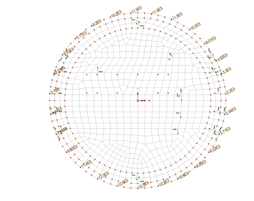
Figure 13 – Non-linear FE analysis of the base slab (WTH Circular Shaft)
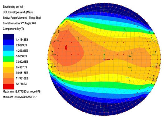
Figure 14 – Wood-Armer moment component My(T) of the base slab (WTH Circular Shaft)
CONSTRUCTION IMPACT ON RIBA E/F DESIGN
Some of the major construction issues that impacted the original design carried out during RIBA E/F and necessitated geotechnical and structural reanalysis and design are listed below. Some of these issues are discussed in more detail in the following paragraphs.
- WB TBM for the X-drive not to penetrate the ETH shaft
- Changes in construction sequence of shaft SH-E3
- Changes in construction sequence at the double basement area of the ETH
- Changes in construction sequence of shaft SH-W2
- Removal of ETH temporary slabs at Level -6
- Change in Cardinal Tower OSD column location at the WTH
- Clashes of foundation of the Farringdon Road retaining wall and the Citigen building column with the station works basement structure
- Mined tunnels and station works
WB TBM for the X-drive not penetrating the ETH shaft
Temporary Lining wall in front of Escalator Shaft ES2 opening was required as RTE2 opening was to made in the west side secant pile wall for the TBM to pass through when the excavation for the shaft has reached to Level -4 slab and lining wall above this level was acting as deep beam. Due to ‘turn and bury’ TBM scheme, WB X Drive TBM will not pass through into the SH-E3 shaft. The opening for RTE2 will now be made only after the shaft is fully excavated and lining wall is complete from L-2 to base slab.
Due to change in construction sequence there is no need to provide temporary lining wall W6 in front of ES2. Revised FE LUSAS analysis was undertaken and lining wall W6 was redesigned (see Figures 15 & 16).
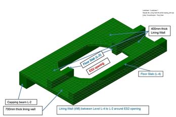
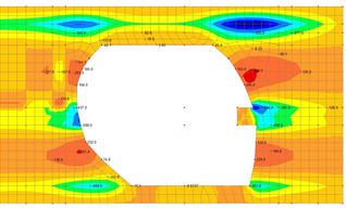
Figure 15 – FE Lusas model of lining wall W6 Figure 16 – Bending Moment My due to Lateral Loads Changes in construction sequence at the double basement area of the ETH
The construction sequence for the ETH double basement has been value engineered in order to simplify and speed up construction and to reduce the risk related to stability of an existing retaining wall during excavation (see Figures 17 & 18). Similarly, the construction sequence has also been amended to allow removal of the temporary horizontal steel props prior to construction of the Level +0 (Ground Floor) slab
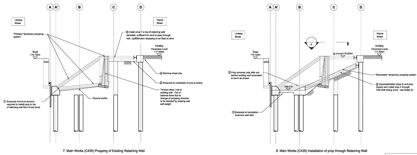
Figure 17 – Original construction sequence (ETH double level basement)
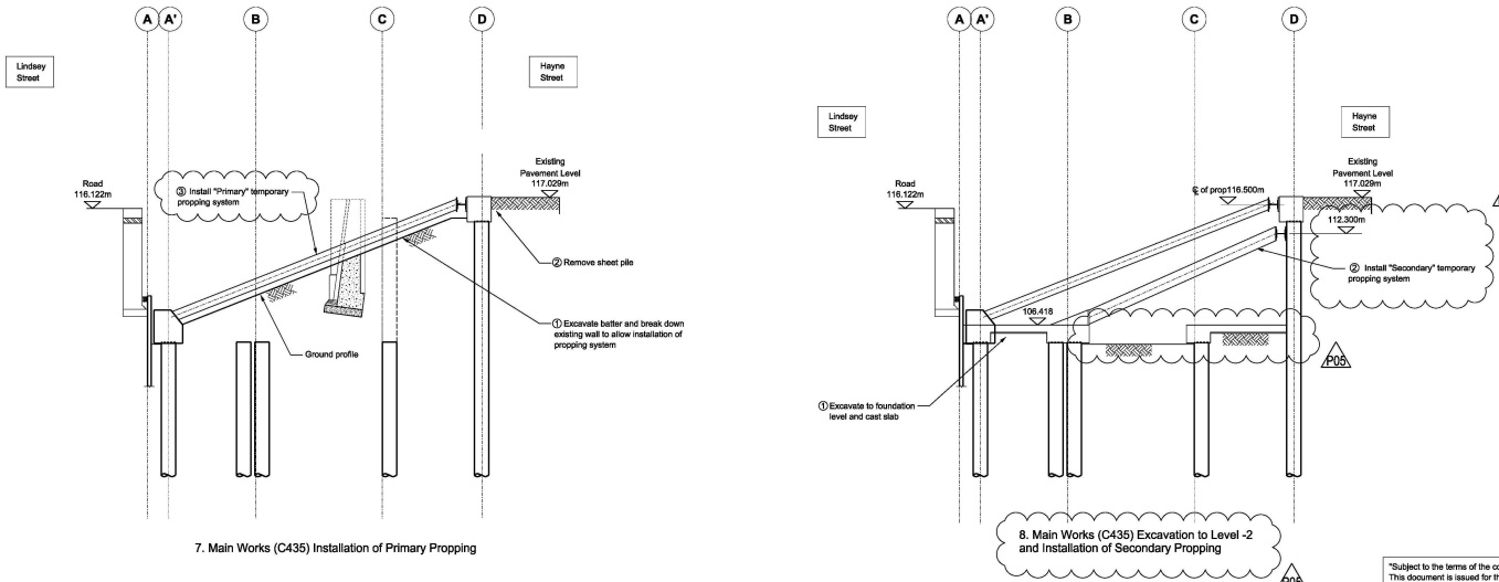
Figure 18 – Revised construction sequence (ETH double level basement)
The C136 geotechnical (see Figure 19) and structural teams carried out reanalysis of the revised construction sequences and checked the adequacy of constructed piles and the structures in this area for forces arising out of revised sequences.
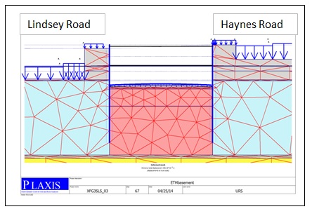
Figure 19 – Geotechnical modelling of the ETH using Plaxis FE Program
Removal of ETH temporary slabs at Level -6
Crossrail track passes through ETH basement level -6 and is supported by trough beams on both sides of the trough slab which supports track slab. The 2.45m deep trough beam will be cast in two operations. The top first 1.15m of the beam will be cast “top down” while the remaining 1.3m of bottom part of the trough beam, trough and track slabs will be cast much later in the programme during “bottom up” construction. During temporary stage, temporary beams and temporary slabs were required for stability and transfer of lateral forces. C435 felt that it would be quite difficult to cast permanent trough slab below the temporary slab.
An alternative scheme was developed in which temporary and permanent beams were strengthened alleviating the need for the temporary slab. The original scheme is shown in Figure 20 while the revised scheme after VE is shown in Figure 21.
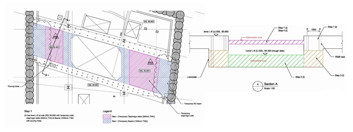
Figure 20 – ETH L-6 Slab constructions (temporary slab shown)
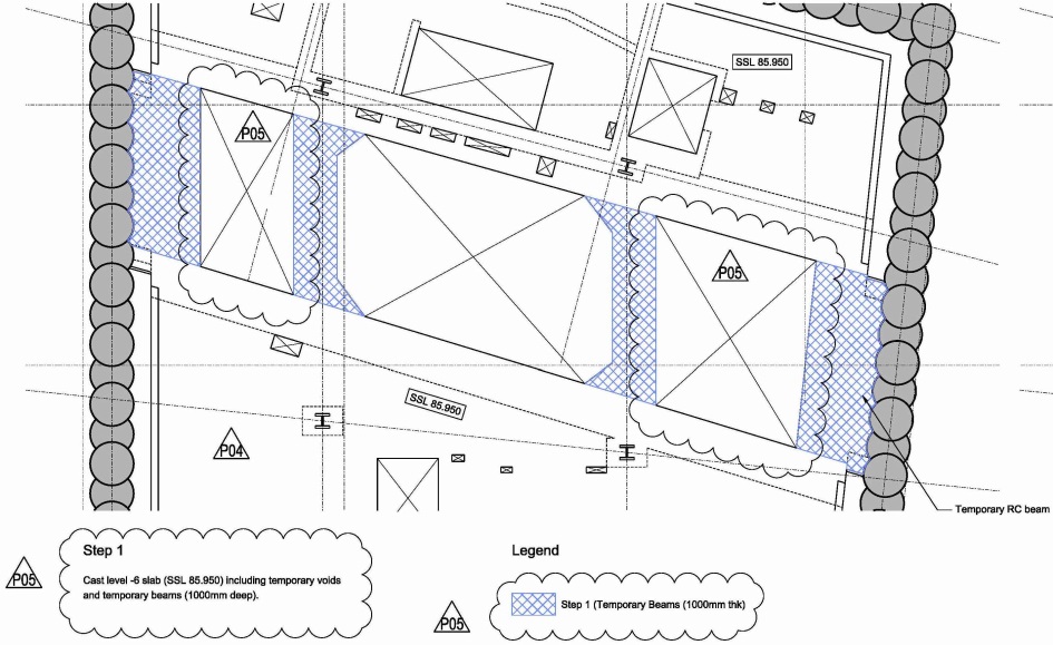
Figure 21 – ETH L-6 Slab constructions after VE (temporary slab removed)
DISCUSSION
The key features of the Farringdon station design can be summarised as follows:
- Located beneath existing buildings and major infrastructure
- Construction of both ticket halls requires demolition of numerous existing buildings
- Two sites (300m apart)
- Construction adjacent to red route [Farringdon Road] – which cannot be closed. Adjacent to numerous roads which serve Smithfield Market
- Adjacent to Grade II* listed building [Smithfield Market]
- Mined SCL platforms with pilot TBM
- Very complex, poor, faulted ground. Water bearing gravels
- Four TBMs terminate at site. Mixture of top-down and bottom up construction.
- Three local authorities involved [Camden & Islington Boroughs and City of London]
- Shared concourse integrated with Thameslink. Indirect link to Circle, Hammersmith & City and Metropolitan LU Lines at Farringdon, and direct link to LU lines at Barbican.
- Two OSDs (“collaborative” and “non-collaborative”). Construction of associated crash decks and the provision of additional foundation and substructure capacity.
Ground movements are a function of wall deflection and these were controlled by a combination of the sequence of excavation and the stiffness of perimeter walls and of the horizontal props. At Farringdon, the need to construct very deep, irregularly shaped shafts on sites with difficult access, close to rail infrastructure, meant that a secant bored pile solution was more appropriate. Top down construction was used except where ground movements were not critical or where programme requirements dictated the need to complete shaft excavation at the earliest opportunity (as is the case for the rectangular shaft at the WTH).
CONCLUSION
The station design has to fulfil performance requirements, in addition to controlling the ground movements and integrating the tunnelling operations. The particular constraints of the site have resulted in suitable structural forms and construction methodologies appropriate to the location.
Due to changes in the construction sequence (to suit contractor’s preferred construction methodology, ease of construction and tunnelling strategies), a reanalysis of several structures has been necessitated during the construction process. A team of FDC engineers has been providing the support during the entire construction period.
The heavy civils and structural elements of the station are currently under construction and this will give way to the following fit-outs and trial running, due to complete2017 and commissioning of Crossrail operations in 2018. It is hoped that the Crossrail station will become catalyst for regeneration of this area and will bring new business opportunities.
References
[1] Crossrail Daily TBM Progress Report
[2] Geotechnical Report: C136 – Farringdon: Groundwater Control and Pore Water Depressurisation RIBA E Advance Works, Document No: C136-SWN-C2-RGN-M123-00005_V3.0
[3] Geotechnical Section Westbound Tunnel, Drawing No: C136-SWN-C2-DDL-M123_Z-00004_P01
[4] Farringdon RIBA Stage D Report VOLUME 1, Document No: C136-SWN-Z-RSR-M123-00001
[5] Farringdon Weekly progress meeting
[6] Crossrail Daily SCL Reports
[7] Eurocodes BS EN series (all relevant parts)
[8] Crossrail Civil Engineering Design Standard (all relevant parts)
-
Authors

