An innovative Verification Process speeds construction of Crossrail’s Moorgate shaft
Document
type: Technical Paper
Author:
Imran Farooq BSc MSc CEng MICE MASCE, David Place BSc(Eng) CEng MICE, Brian Steele BEng CEng MICE, Hock Liong Liew BEng MEng PE(Civil) Singapore, Sergio Vitorino BSc, ICE Publishing
Publication
Date: 31/08/2016
-
Read the full document
Introduction
Crossrail’s Liverpool Street station will serve the City of London and provide interchanges with London Underground’s Northern, Central, Metropolitan, Circle and Hammersmith & City Lines, connections to Stansted airport and National Rail services at Liverpool Street and Moorgate stations. Built at deep level to pass beneath LU’s Northern and Central Lines, the new platforms extend between the existing Liverpool Street and Moorgate stations with both stations having access to the Crossrail station. With Crossrail operating 24 trains/hour, 26 million people per year will use the new station.
In the morning peak Crossrail services will deliver some 8000 passengers per hour at Moorgate. The existing Moorgate station ticket hall is being enlarged to create an integrated western ticket hall from which a bank of three escalators will descend to an intermediate concourse, whence a further bank of three descends to the platform central concourse 35m below street level. This entailed the construction of the deepest shaft on Crossrail to 42m below street level (113m ATD), all within one of Crossrail’s most constrained sites (Figure 1), bounded by the Metropolitan Line to the north, the Northern Line tunnels to the east, listed buildings immediately to the south and the existing Moorgate station ticket hall nearby. The shaft’s 8 levels of basement accommodate the upper bank of escalators, lifts and emergency escape stairs from platform level, tunnel forced ventilation (60m2), draught relief ( 40m2), smoke extract (10m2) and associated plant rooms.
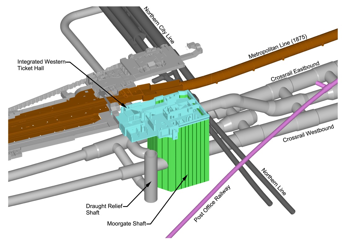
Figure 1 – 3D CAD model of Moorgate shaft and adjacent tunnels The westbound running tunnel passing through the shaft placed the shaft on the critical path for completion of the 8.2 km long Y-drive tunnels being driven by TBM from Limmo to Farringdon. The shaft had to be completed by the end of November 2014 to allow construction of the launch chamber to speed TBM Victoria on her way to Farringdon. The timely passage of the TBM through Liverpool Street Station was fundamental in meeting the Crossrail critical path programme for the opening of the central London section in December 2018; any delay in the construction of the shaft was untenable.
Design of the shaft
The shaft was designed by Mott MacDonald under the Liverpool Street station design contract C138. It is a diaphragm wall structure, an irregular polygon in plan measuring approximately 35m x 35m as shown in Figure 2, constructed top down with seven reinforced concrete ring beams installed between levels 107.55m and 83.10m ATD as the excavation is taken down in stages. Below the lowest ring beam the westbound running tunnel passes through the shaft and two levels of temporary propping (at 80.5m and 76.0m ATD) were specified to restrain deformation until the 2m deep base slab had been cast at level 74.2m ATD. With the shaft’s east wall less than 5m from the 100 year old northbound tunnel of LU’s Northern Line beneath Moorgate, limitation of deformation to protect nearby assets rather than strength governed the design of the shaft.
The site geology is shown in Figure 3. One anomaly of note was a scour hollow feature, up to 10 m deep within the London Clay, coincident with the footprint of the shaft, which had to be taken into account in the ground model for the design. The RIBA E and F design of the shaft had been carried out using Crossrail Engineering Design Standards (CEDS). These are a project specific compilation based on Eurocodes and British standards, and in terms of clay strata preclude the possibility of using undrained strength and stiffness parameters on the passive side of the excavation. In the original design use of CEDS had led to a structure that required very heavy internal ring beams to stiffen the upper part of the shaft. Below the ring beams there was a combination of two temporary cross walls and the early build of part of the internal structure – a pair of slab strips (3m wide by 1.5m deep) specifically to restrain movement in the east-west direction. In the lowest part of the shaft the two levels of temporary propping were to be provided for further restraint. The intent was to limit wall horizontal movement generally to no more than 45mm in total, but for the east wall adjacent to the Northern Line the limit was a maximum of 30mm. Because of these constraints, for the original design the construction sequence was prescribed in the Works Information drawings – the 11 stages are shown in Figure 4.
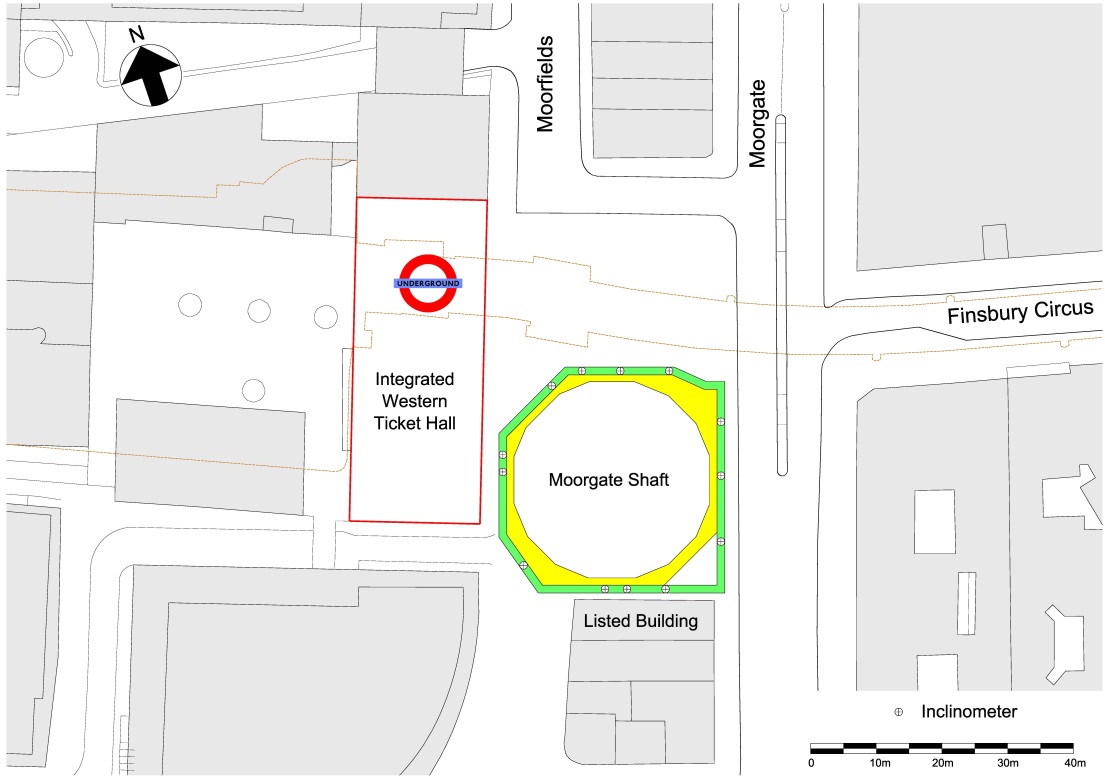
Figure 2 – Moorgate shaft site plan and inclinometer locations 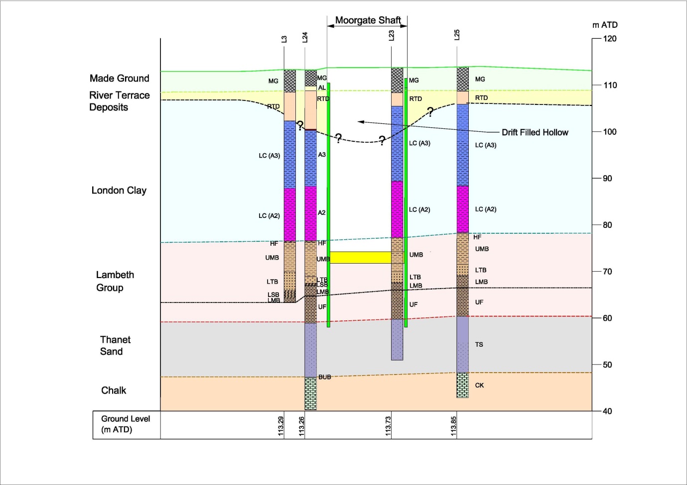
Figure 3 – Moorgate shaft geological section 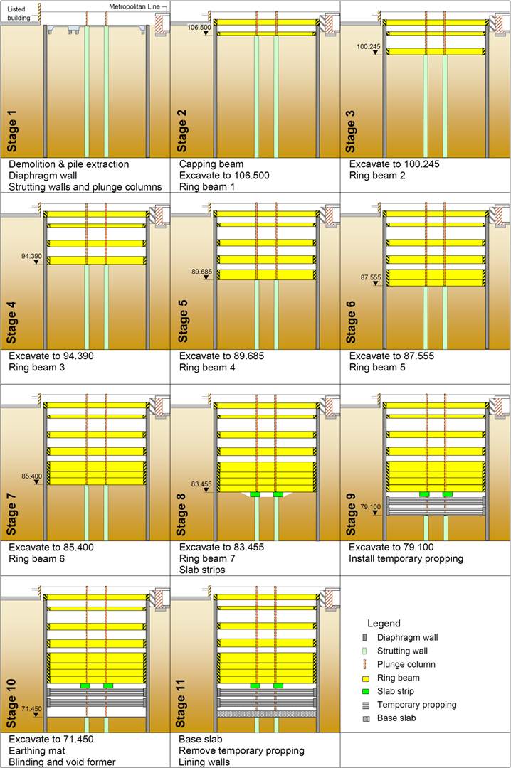
Figure 4 – Moorgate shaft construction sequence for the original design The need for programme acceleration
The C501 construction contract for the Moorgate shaft was awarded in March 2011 to the BAM Nuttall Ltd / Kier Construction Ltd JV (BNK) for a start on site in July 2011. The shaft was to be constructed on the footprint of 89-134 Moorgate, immediately opposite the new Moorgate integrated ticket hall. The building previously occupying the majority of the shaft site was 91-109 Moorgate (Amro Bank), a 1970s 6 storey concrete framed structure with a single storey basement. The building spanned over the LU subsurface tracks and was founded in the main on 900mm diameter bored piles approximately 34 metres long. When this building had been demolished in advance of the C501 shaft construction works contract the piles were left in place.
Removal of the redundant piles became a major issue for the construction programme, with diaphragm wall subcontractor Bauer having to develop a bespoke extraction machine to clear the footprint of the shaft before the diaphragm walls could be started. On completion of pile removal the programme delay was 11 months, so work on the 55m deep 1.2m thick diaphragm wall panels did not start until the end of January 2013. By the time the diaphragm walling was completed in August, the project milestone for handover to the C510 SCL tunnel contractor at the end of November appeared to be a forlorn hope.
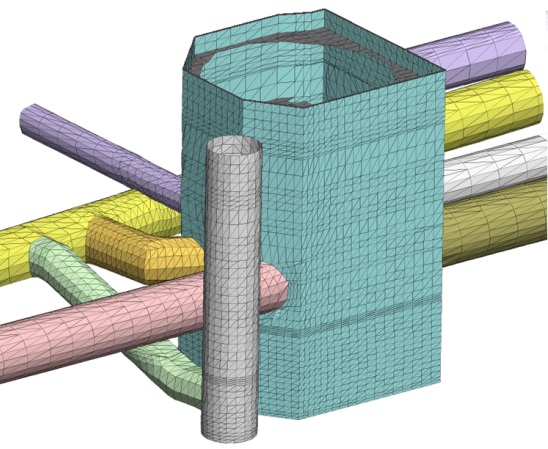
Figure 5 – 3D FLAC model of Moorgate shaft and adjacent tunnels To mitigate the delay, in April 2013 designer Mott MacDonald had proposed reanalysis of the shaft using non-linear soil parameters, and state of the art soil structure interaction modelling using FLAC 3D. Crossrail granted a concession against CEDs to allow use of undrained conditions on the active side for fine grained soils provided that the duration of the excavation down from the London Clay horizon (100.4m ATD) to completion of final excavation level (71.45m ATD) was less than one year. The designers embarked on reassessment of the shaft including 3D numerical modelling of the actual construction sequence of both the shaft and the adjoining SCL tunnels. The reanalysis used the well-established method of implementing non-linear stress-strain characteristics for heavily over-consolidated soils (via a stiffness degradation curve) in numerical modelling as outlined by Jardine [1] The shaft and SCL tunnels are represented by some 55,000 linear elastic three-noded flat shell elements in the 3D FLAC model as shown in Figure 5 (the approx. 270,000 eight-noded brick elements with non-linear stiffness and Mohr-Coulomb failure criteria representing the soil are not shown). The outcome was that the lower level of temporary propping at 76.0m ATD could be omitted. It was also identified that there was potential for omission of the temporary propping at 80.5m ATD as well so that at the bottom of the shaft the diaphragm wall spanned 12m between the lowest ring beam and the final excavation level at 71.45m ATD.
At this time the first two of the 11 construction stages had been completed. To maximise future programme benefit, Mott MacDonald conducted a value engineering review of the remaining stages. As the contractor was placing blinding around the perimeter of the shaft to support the construction of each ring beam, recent case history by Powderham on the use of temporary blinding slabs to mitigate softening of the ground and control wall movement for the Heathrow Airside Road Tunnel [2] was integral to this review. It was considered that by placing intermediate blinding slabs across the entire shaft at the completion of the dig for each excavation stage, construction stages 5 and 6 could be combined, (i.e. the excavation for ring beams 4 and 5 could be done in one continuous dig and the ring beams then cast sequentially), and there could be opportunity for the combination of two further stages (7 and 8) and also the omission of the slab strips.
The observation based Verification Process
However the highest priority was the omission of the temporary propping at 80.5m ATD as its installation would take several weeks, and whilst in place it would severely constrain access for the lowest level of excavation and subsequent construction of the base slab. Furthermore the TBM could not transit through the shaft with this propping in place. Hence it was necessary to develop a methodology that evaluated value engineering opportunities on the basis that the omission of the 80.5m ATD propping was not jeopardised, and an observation based Verification Process was proposed.
With Crossrail’s support Mott MacDonald developed a carefully defined and controlled observation based Verification Process. The difference between an observation based verification method and the conventional observation method is that in the latter the contingency measures are only implemented if trigger levels are breached, whereas with the verification process all such measures are included in the design, and will only be omitted when projection based on observations during construction confirm they are not needed. This approach is a practical application of Bayesian inference [3] where the probability for the hypothesis is updated (hypothesis being the potential prop removal) as data is acquired (data being the observed shaft behaviour during construction).
This approach provides the project with a bounded programme. Accordingly, the construction sequence drawings were re-detailed to show four intermediate blinding slabs, the slab strips, and the 80.5m ATD temporary propping all to be constructed as mitigation measures, but with the Project Manager having the authority to instruct their omission should the outcomes from the Verification Process be favourable.
Key requirements for the use of the observation based Verification Process are:
- High quality real time monitoring of wall movement, ground settlements, pore pressures and heave within the excavation are essential.
- Use of a non-linear ground model capable of capturing soil structure interaction in a calibrated numerical model.
- Multiple iterations calibrating the soil model to observed behaviour are carried out.
- Close collaboration between contractor, designer and client is necessary, with frequent meetings to review the outcome from modelling and potential changes to construction activities.
- At each stage a fully assured set of construction sequence drawings is produced in parallel with the analysis so that favourable outcomes can be instructed and implemented without delay.
For the Verification Process the A* soil model based on the approach outlined by O’Brien et al [4] [5] was adopted. For this model the ground stiffness parameters were derived through a holistic framework that considers both field and laboratory test data to determine key ground parameters, and included back-analysis of case histories of tunnel construction for the Heathrow Express and the King’s Cross SCL tunnels. This A* model was already being used by Mott MacDonald for the adjacent Crossrail SCL tunnel design, and the monitored SCL lining movements were broadly in agreement with the numerical modelling predictions. Figures 6(a) and 6(b) show non-linear stiffness profiles for the London Clay and the Lambeth Group respectively (the A* model is the blue line and the approach based on Jardine is the green line).
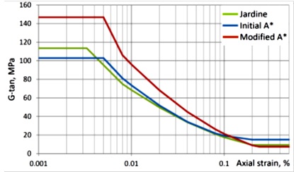
Figure 6a – Non-linear Stiffness Profiles London Clay 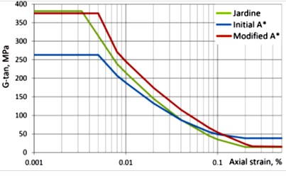
Figure 6b – Non-linear Stiffness Profiles Lambeth Group Monitoring Strategy
A comprehensive monitoring strategy had already been implemented to provide control of wall displacements to pre-agreed limits to ensure the integrity of adjacent infrastructure. This monitoring system was enhanced to provide a real time assessment of the structural performance of the shaft within the footprint of the structure so that it included 13 inclinometers in the diaphragm walls (in-place inclinometers, manual inclinometers and ShapeAccelArrays were installed as shown in Figure 2), magnet extensometers to measure heave, vibrating wire piezometers to monitor pore water pressures in the Lambeth Group, standpipes to monitor groundwater levels in the Lower Aquifer and strain gauges with temperature measurement to monitor stresses in each ring beam. Empty inclinometer tubes had also been installed adjacent to each inclinometer to provide redundancy in the monitoring scheme. To verify inclinometer readings and to increase confidence in the measured wall displacements, mini-prism survey points were installed on the face of ring beams and monitored on a daily basis. Laser extensometer survey points were installed when excavation progressed into the Lambeth Group to monitor convergence of the walls.
Implementation of Observation based Verification Process
The Verification Process was based on real time assessment of data and had to be linked to the defined construction sequence stages as work progressed on site. To manage the Verification Process three verification points (VPs) were defined. Successive calibration of the FLAC numerical model against wall movement data was to be undertaken once the excavation reached 94.19m ATD (VP1), 87,355m ATD (VP2) and 82.9m ATD (VP3) respectively to assess the potential omission of the propping and combination of construction stages, together with variations to mitigation measures should wall movements approach trigger levels.
Additional mitigation measures comprising an intermediate blinding slab at excavation levels 94.19m, 87.355m, 82.9m and 79.1m ATD were introduced. These slabs were specified as 200mm minimum thickness unreinforced 20N/mm2 structural concrete for early strength gain, to be cast within 24 hours of completing the dig. Initially the scope of the Verification Process considered omission of these intermediate blinding slabs at each of the verification points, however in the event, due to their effectiveness, none of these were omitted.
All mitigation measures were required from the outset to provide certainty for the construction programme’s end date, such that any subsequent changes would be beneficial in bringing that end date forward. All the mitigation measures were included explicitly on revised construction sequence drawings, whereas previously only the temporary propping and slab strips had been shown. The construction sequence drawings retained the original top down sequence for constructing the ring beams from Stage 5 downwards in four horizontal slices. Then the Verification Process was started to consider the omission of the mitigation measures and the combination of Stages 7 and 8 (excavation to 85.4m and 83.455m ATD, and construction of ring beams 6 and 7). The construction sequence drawings were modified as necessary as the process progressed to each verification point (VP). To facilitate understanding the Verification Process, a detailed flow chart was produced and presented to the Crossrail delivery team and the Contractor (an abridged version is shown in Figure 7). The desired outcomes and the target verification points for the decision on incorporation are summarised below:-
► VP1 Omission of slab strips
► VP2 Combine stages 7 & 8
► VP3 Omission of propping at 80.5m
The following activities were undertaken during all three VP periods:
- Wall displacement data from the monitoring is processed. Daily monitoring data was averaged and anomalies were isolated. Stage-by-stage monitoring data was plotted out and compared with wall displacement previously predicted by the FLAC 3D analysis.
- The existing FLAC 3D model is updated to incorporate:
- actual sequence as built and best prediction still to go for SCL tunnelling;
- more accurate topography of the ground around the shaft;
- more accurate drift filled hollow geometry;
- refined ring beam geometry; and
- modified ring beam and crosswall stiffness to replicate observed shaft behaviour.
- Revised wall displacement predictions from the new FLAC 3D models were plotted against monitoring results for each stage. Revised predictions for the subsequent stages were also plotted to allow for immediate comparison for subsequent stages of excavation.
- Category III checks were carried out in parallel to provide an assured design at each verification point, with the real time raw and processed data being provided to the Category III Checker.
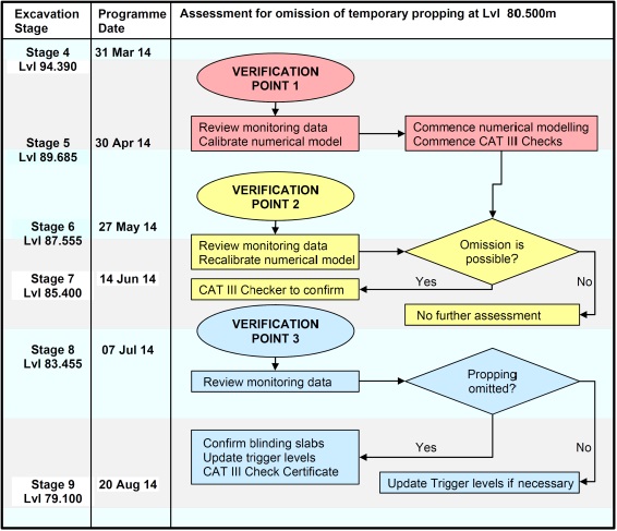
Figure 7 – Flow chart for Verification Process Verification Point 1 (VP1) was started on 10 April 2014 when the excavation level had reached 94.19m ATD, and the first 200mm intermediate blinding slab was cast at this stage.
It took about five weeks to complete the VP1 process Based on the results the North, West and South walls showed a reasonably conservative match between prediction and monitoring (i.e. predictions were higher than measured movements). The predicted results for the dig from 94.190m to 87.355m ATD also showed that there was a reasonably conservative match. However results for the East wall were different; prediction was lower than measured movements as shown in Figure 8. The reliability of inclinometer data from the East wall was initially questioned by the design team as there was a good match on the other three walls. Furthermore the effectiveness of the two unreinforced concrete crosswalls in the east-west direction was questioned.
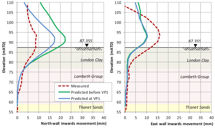
Figure 8 – Wall movements at VP1 As part of investigating the cause of the greater than expected East wall movement, it was identified that permeation grouting had been carried out adjacent to the East wall concurrently with the excavation in Moorgate shaft. It was considered possible that the grouting could have been a contributing factor to the higher movements of the East wall, and this view was supported by monitoring data from nearby third party assets. Based on the results from the North, South and West walls, it was concluded that there was a high probability that the temporary props at 80.5m ATD and the slab strips could be omitted. However, as the predicted movements at the East wall were lower than the measured movements, it was recommended that the decision for the omission of the slab strips should be deferred to the next verification point (VP2), and the potential effect of the permeation grouting on the East wall be assessed further.
Verification Point 2 (VP2) was started when excavation had reached 87.355m ATD on 18 May 2014. The 200mm intermediate blinding slab was cast at this level on 19 May. VP2 was completed on 2 June when the excavation level was still at 87.355m ATD. Based on back analysis of the ground movements at the shaft, the constitutive non-linear A* soil model was modified to the red line in Figures 6(a) and 6(b). The key modification was for the calculation of initial isotropic stiffness where the horizontal stiffness at very small strain has been considered in the calculation since the horizontal displacements were likely to dominate the response of the walls of the shaft. Due to the close proximity to the Northern Line tunnels it was essential to understand the variation between the East wall predictions and measured movements, and so the scope of the VP2 was extended to include:
- Assessment of the effects of permeation grouting on the shaft, modelled by applying grouting pressure over the zone between 104m and 100m ATD in the FLAC model.
- Sensitivity analyses to assess the potential effects of a “relic shear zone” behind the East wall, by varying grout pressures and increasing soil unit weight within the grouted zone.
- Assessment of the effect of reduction in crosswall stiffnesses.
Since the crosswall panels that abut the diaphragm wall and the corresponding diaphragm wall panels were constructed individually, there was concern that there could be clay inclusions at the junction between the ends of the crosswalls and the face of the diaphragm wall panels. Field observation of the crosswall junctions was carried out when the excavation level was at approximately 87m ATD and was continued until the excavation level had reached the final formation level at 71.45m ATD. Continuous clay inclusions were seen to be present between diaphragm wall and crosswalls, however the clay had not failed and there was a load transfer mechanism present (this was also confirmed by calculation).
To account for this effect, the FLAC models were run with various crosswall stiffnesses (full stiffness, 10% stiffness and zero stiffness). For the North and South walls, the revised FLAC modelling showed an even better match giving confidence that the modified ground parameters in FLAC were more realistic. For the East wall, both the deflected shape between level 90m and 110m ATD, and the top movement were still not fully replicated by the FLAC 3D models in VP2. Therefore a bounded approach was used for the East wall. The upper bound East wall projection for excavation to full depth increased (with temporary propping removed) to approximately 32mm which was higher than the “Red” trigger level (i.e. 30mm), see Figure 9.
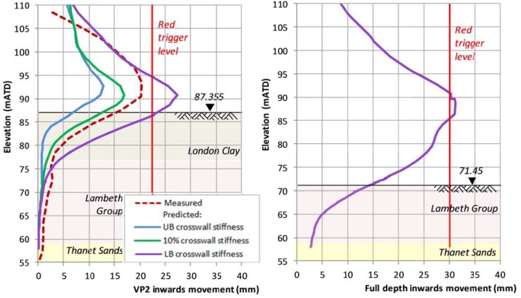
Figure 9 – East wall movements at VP2 Based on the analysis results, it was concluded that there was a high degree of confidence that the temporary propping at 80.5m ATD could be omitted and that construction stages 7 and 8 could be combined without jeopardising the omission of that propping. By combining these two stages so that the excavation could be done in one continuous dig and the ring beams then cast sequentially, the total construction time would be reduced, thus limiting secondary ground movement due to softening of the London Clay. However there appeared to be a temperature related ratcheting effect on the shaft walls (more pronounced on the East wall) that required further investigation.
Furthermore VP2 had identified that there was a high risk that the 30mm ‘red’ trigger level for the East wall could be breached if contingency measure were omitted. Hence the decision to omit the slab strips was deferred until the effects on the LU Northern Line tunnels of ground movement due to all the Crossrail works in the vicinity up to that time had been reviewed, and the residual capacity for the tunnels to tolerate further ground movement had been assessed. Effectively this was to determine if there was scope for a relaxation of the “red” trigger levels for the East wall. Therefore whilst there was a higher degree of confidence that the omission of the slab strips would not compromise the omission of the propping at 80.500m ATD, as an additional contingency the design for an alternative simplified propping slab cast directly on the blinding was to be prepared in parallel in case results from VP3 were not favourable.
The diurnal temperature related movements that were observed when grouting was being carried out during late spring when large daily temperature changes were occurring were unexpected. The magnitude of accumulated movement at the top of the east wall was not observed to the same degree on the other three walls where grouting was not carried out. The designers postulated that likely explanation for this anomaly was that whenever the shaft moved inwards due to decreasing ambient temperature, the grouting taking place locally behind the east wall would stiffen the ground. Consequently the east wall could not move back into its original place during temperature reversal, and in each subsequent diurnal temperature cycle would move slightly further in; effectively there was a slow ratcheting movement inwards into the shaft (this will be subject of a separate paper).
Verification Point 3 (VP3) was started when excavation reached 82.900m ATD on 2 July 2014, and the 200mm intermediate blinding slab was cast at this level on 3 July. VP3 was completed on 25 July three weeks later. The following additional activities were introduced during the VP3 period:
- Diurnal temperature related movement of the shaft (leading to ratcheting) was replicated by using reduced ring beam stiffness to match the contracted state of the ring beams.
- The geometry and stiffness of all the ring beams was further optimised to incorporate the potential restraining effects of the temporary construction jetty.
- Pore pressure measurements and measured ring beam convergence were compared to the predictions from the updated FLAC modelling.
- Additional parametric studies were undertaken to assess the potential effects of limiting suction in the FLAC analysis and sensitivity analysis of potential changes in Lambeth Group geology.
Meanwhile meetings between London Underground and Crossrail’s asset protection consultant had led to agreement on the relaxation of the “red” trigger level for the East wall from 30mm to 40mm. The results of the FLAC modelling for all the walls were plotted and compared with monitored movements. All movement predictions including the East wall were within the new “Red” trigger level of 40mm as shown in Figure 10. The results also showed that the potential effects on the Northern Line tunnels due to shaft excavation-induced movements were minimal. The predicted short term settlement of the tunnels due to the cumulative effect of the shaft excavation was less than 10mm.
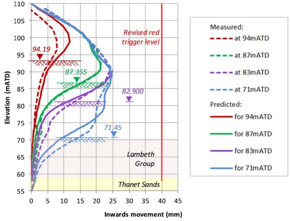
Figure 10 – East wall movements at VP3 The results at the end of VP3 showed a good match to the accumulated East wall movements, representing a significant improvement from VP2. Previously anomalous movement at the top of the East wall were considered to be most likely due to combined effects from diurnal temperature (ratcheting) and permeation grouting together with reduced crosswall stiffness. Therefore it was concluded that the temporary propping at 80.5m ATD and the slab strips could be omitted without having to provide the alternative simplified propping slab. The progression of the construction sequence from the original design to the actual as-built sequence after completion of the Verification Process is shown in Figure 11.
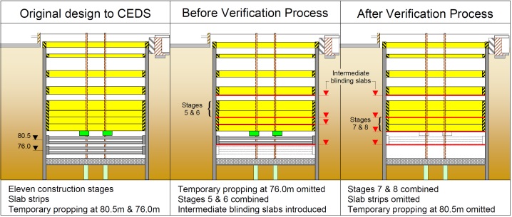
Figure 11 – Changes to the construction sequence Conclusion
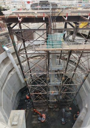
The Verification Process was implemented successfully and achieved the required objective of an accelerated construction programme that allowed the Project critical milestone for handover of the shaft to the SCL tunnel contractor to be met. The Moorgate shaft excavation was bottomed out on 1st October (Figure 12) and the 1800m3 concrete pour for the base slab was completed on 1st November, two weeks ahead of programme [6]. Crossrail Director Central Section Bill Tucker said: “This achievement is a culmination of an extraordinary story of collaboration between the contractor, designers and CRL. Looking back six months ago there were many doubts about the ability to excavate, construct and bottom-out the shaft on programme and the teams did it!” TBM Victoria transited through the shaft in April 2015 and was launched on her way to Farringdon on 13th April 2015. In June 2015 the Accelerated Programme for the Moorgate Shaft at Crossrail’s Liverpool Street Station won the Editor’s Award at the Ground Engineering Awards
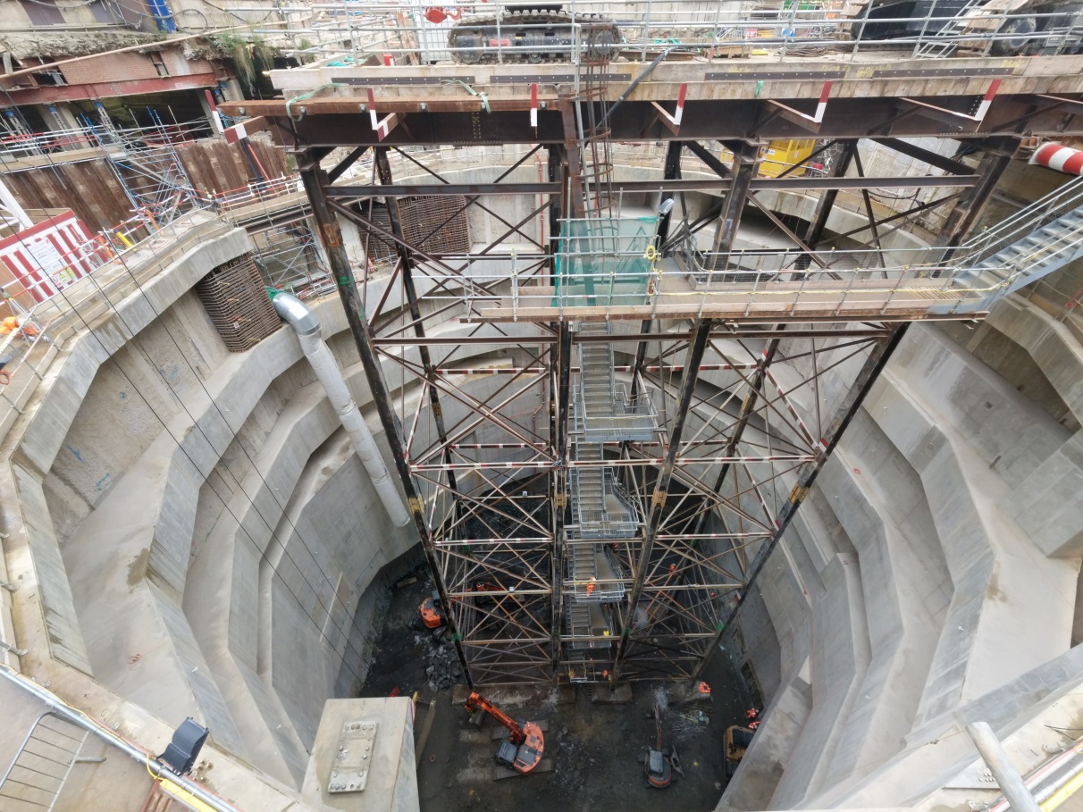
Figure 12 – Moorgate shaft excavation to 71.250 m ATD The entire process was peer reviewed both internally by Mott MacDonald, and also by Crossrail Central Engineering Group (CEG) and their independent consultants. Throughout, the construction sequence drawings were progressively revised, and each revision was subject to Category 3 check, thereby maintaining full design assurance. Due to the small magnitude of the wall movements, typically only a few millimetres at each stage of the excavation, the Verification Process required careful consideration of all aspects of the as constructed geometry, and soil and ground parameters. After a number of iterations, and following the process through the three verification points, the design team were able to arrive at validations and predictions that were reliably close to measured movements, and hence give the assurance required to omit the propping and combine excavation stages.
The following key technical points can be made:
- Use of blinding slabs has been an effective way of controlling wall movements. Their use reduced ground softening and provided propping through diaphragm action. Conversely the strutting walls were less effective than expected.
- Expedited construction limits the amount of softening occurring in clays. Installing temporary propping during excavation (although this stiffens the structure) can be counter-productive as the time required to install the propping itself can allow the clay to soften, (especially when complex temporary propping is required). Hence when temporary propping is required to limit wall movement, use of an observational approach can provide a quicker and more cost- effective way of achieving the same goal.
- Use of an observational approach requires close collaboration between Designer, Contractor and Client’s site team. With this approach the construction drawings have to be progressively updated and assured, and issued to the contractor for construction within very short time frames.
- The combined effect of grouting to stiffen the ground prior to tunnelling, and diurnal temperature variations contributed to the atypical behaviour of the East wall, causing a slow ratcheting in the wall movements.
References
- Jardine et al (1986) Studies of the influence of non-linear stress-strain characteristics in soil-structure interaction. Geotechnique 36, No. 3, 377-396, ICE, London.
- Powderham (2009) The Observational Method – using safety as a driver for innovation. Vienna Terzaghi Lecture, Österreichischer Ingenieur-und Architekten-Verein, Austria.
- Fienberg (2006) When did Bayesian inference become “Bayesian”? Bayesian Analysis Volume 1, Number 1 March 2006.
- Eadington & O’Brien (2011) Stiffness Parameters for a Deep Tunnel – Developing a robust parameter selection framework. Proceedings of the 15th ECSMGE, Athens.
- O’Brien & Harris (2013) Geotechnical Characterisation, Recent Developments and Applications. 12th International Conference on Underground Construction, Prague.
- Douglas, Smith & Hunter (2015) Delivering the Moorgate shaft base slab on Crossrail, UK. ICE Proceedings, November 2015.
-
Authors

Imran Farooq BSc MSc CEng MICE MASCE - Mott MacDonald
Technical Director
David Place BSc(Eng) CEng MICE - Mott MacDonald
Technical Director
Brian Steele BEng CEng MICE - Crossrail Ltd
Engineering Manager
Hock Liong Liew BEng MEng PE(Civil) Singapore - Mott MacDonald
Principal Geotechnical Engineer
Sergio Vitorino BSc
Geotechnical Engineer, formerly Mott MacDonald
