The Lambeth Group in the Crossrail Project of London, UK – the geological model
Document
type: Technical Paper
Author:
J. A. Skipper, H. E. Scholes, Dr Ursula Lawrence PhD Eur.Geol C.Geol FGS C.Sci, M. Packer, Chris Menkiti, ICE Publishing
Publication
Date: 07/09/2015
-
Read the full document
1 Project Background
Crossrail is one of the most significant infrastructure projects ever undertaken in the UK. With a £14.8bn funding envelope, Crossrail will provide a high frequency, high capacity train service serving 40 stations and linking Reading and Heathrow in the west of London, to Shenfield and Abbey Wood in the east. These above ground sections of the route will be linked via twin, 21km tunnels up to 40m deep under central London. This requires the excavation of circa 8M m3 of soil, which is being recycled to create a new bird sanctuary on the coast of Essex. The central London tunneled section of this project has involved, since 2000, the specification for, drilling and interpretation of 1,043 new ground investigation boreholes. Information from a further 653 boreholes by third parties or historic sources have also been incorporated into the ground model. Approximately 10 km of the tunnel route (Figure 1) is within the sediments of the Lambeth Group and more than 10,700 tests have been undertaken specifically on these sediments alone – more than any previous project. Six Earth Pressure Balance Tunnel Boring Machines (EPBMs) are being used for the main tunnel sections, while two slurry TBMs are being used for the most easterly tunnel sections which are primarily in Chalk.
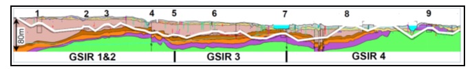
Figure 1 – Crossrail main tunnel cross section, west-east, excluding branch to Pudding Mill Lane. GSIRs = Geotechnical Site Investigation Reports. Stations: 1=Paddington, 2=Bond Street, 3=Tottenham Court Road, 4=Farringdon, 5=Liverpool Street, 6=Whitechapel, 7=Canary Wharf, 8=Custom House, 9=Woolwich. Tunnel =white line. Lambeth Group = brown layer (above Mid Lambeth Hiatus) and orange layer (below MLH). In monochrome volume, Upper and Lower Lambeth and Thanet Sand appear as darker layers.
2 Lambeth Group Background
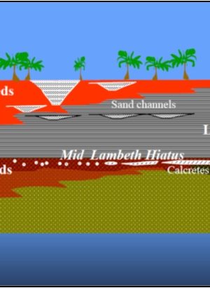
The Lambeth Group (hereafter, Lambeth) is a group of sediments that is highly variable, laterally and vertically. Its clays, sands, gravels and silts were deposited 55 to 56 million years ago, in complex shallow marine to terrestrial environments (Figure 2). During deposition there were overall at least three cycles of sea level rise and fall, much tectonism and volcanic ash falls, and a sub-tropical climate (see Entwisle et al 2013 for details). Up to 18 different sub-units may be present but not all these units are present at any given location.
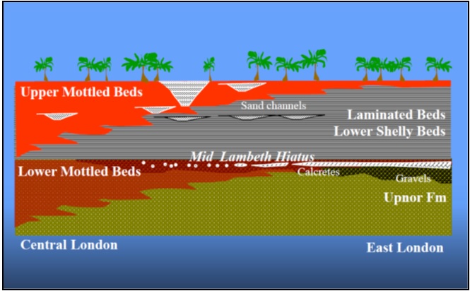
Figure 2 – Lambeth Group. depositional variability
Despite only being a maximum of 15m to 20m thick in the London area, the sediments are associated with many engineering risks including:
- Presence of hard bands
- Mixed face/ ground conditions
- Presence of laminated sand/clay layers and sand- or gravel- filled channels
- Excavation instability – loose soils
- Complex groundwater levels and pressures
- Pyrite, expansive clays, oxidising minerals (see Newman et al 2013 for details of latter)
- Complexity from faulting
- Differential settlement
Historically, some ground investigations in the Lambeth (formerly the Woolwich and Reading Beds) have been poorly interpreted, with baffling classifications. Resulting geotechnical properties led in turn to over-confident or conservative design values. Page & Skipper (2000) took Ellison et al.’s 1994 stratigraphy of the Lambeth and adapted the lithologies using a sequence stratigraphical approach (based on Skipper 1999). This overcame many engineering classification difficulties, and introduced the use of a major, recognizable sea level boundary (the Mid Lambeth Hiatus, hereafter MLH, see Figures 1 to 3) as an aid to interpretation. This planar boundary may be recognised by the presence of oxidised sediments below and reduced sediments above – a critical marker for correlation between boreholes.
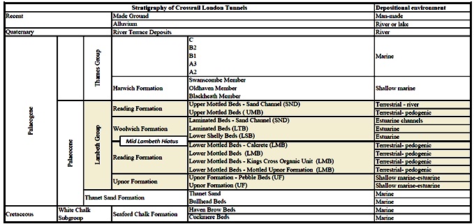
Figure 3 – Stratigraphy of Crossrail London tunnels geology including depositional environments. Lambeth Group is shaded.
Crossrail was the first project to fully utilize this revised system and the first to also utilize Project Specific Geological Training (Skipper 2008) from desk study to construction. From 2000 approximately 500 Crossrail staff, consultants and contractors attended the training courses (which covered the entire project geological sequence). These promoted understanding the stratigraphy, classification and ground risks at every project stage. It resulted in a very detailed ground model which has significantly increased our understanding of these deposits, and our ability to predict lithology location and geometry in order to address their engineering behaviour.
3 Ground Issues
Although rotary cored boreholes were generally the best and most complete drilling technique for identification of lithologies and obtaining high quality samples for testing, the sands and especially the Upnor gravels are often poorly recovered. Rotary boreholes also do not record ground water strikes. A combination of predominantly rotary and supplementary cable percussive boreholes were therefore specified for the ground investigations (GI). The cable percussion boreholes were used particularly at stations, shafts cross-passages and portals. Site supervision prioritizing good communication with drillers and site staff reaped rewards in terms of best recovery. Good illumination was key for logging facilities, since in poor light even the highly coloured Reading Formation Mottled Beds can look like London Clay, and important boundaries and faults can be missed. Highly variable clay mineralogy of the Lambeth sediments (Huggett and Knox 2006) leads to varying percentages of swelling smectitic clays, particularly in the Upnor Formation. The clay fraction shrinks rapidly after core opening, leaving what might have been a sandy CLAY in situ as a slightly clayey SAND after drying. To prevent errors of engineering geological description, loggers were requested to add water and rework samples, adding a note to the main description that states, e.g. “reworks as a sandy clay”.
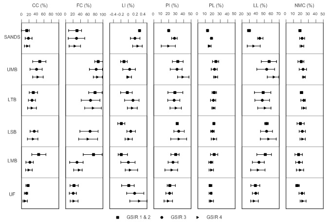
Figure 4 – Index tests from the Lambeth Group in the Crossrail project divided by principal lithological units and west to east by the Sectional Geotechnical Interpretative Reports areas (GSIR 1-3, see Figure 1). UMB=Upper Mottled Beds, LTB= Laminated Beds, LSB=Lower Shelly Beds, LMB=Lower Mottled Beds, UF=Upnor Formation.CC=clay content, FC=fines content, LI=Liquidity Index, PI=Plasticity Index, PL=Plastic Limit, LL=Liquid Limit, NMC=Natural Moisture Content. Standard Penetration Tests (STPs) were not included as they are so variable that even a single site produces a scattergun plot.
4 Sand Channels
From early versions of the Crossrail long section it was clear that sand channels were more common in the Lambeth Group than was previously thought, occurring commonly in both Upper and (occasionally) Lower Mottled Beds. In the Upper Mottled Beds, one very large channel (up to 12.5m deep and 300m wide) was found at the interchange with Bond Street Station, the base of which cut down into the Lower Mottled Beds, although smaller channels were more commonly seen. Discreet channels up to 5m wide and 2m deep had been recognised in the Woolwich Fm Laminated Beds from Stratford High Speed 1 Box, but it was clear on Crossrail that these were extremely common in the Laminated Beds, and even if there was no sign in a borehole, it should be assumed that a channel could be close by laterally. Laminated Beds sand channels were less common west of Tottenham Court Road, where the entire Woolwich thins to less than 2m. Channels frequently have relatively high permeability and can contribute to low stability in units above them if ground water is not adequately controlled, so recognition is vital. Sand channels in the upper part of the Lambeth Group were noted as being recharged independently to the lower Lambeth. At Bond Crossrail Street Station, where the 300m wide sand channel was completely dewatered to allow box construction, the water table recovered at a rate of 4m/year in one year following dewatering. In London’s West End, the Upnor Formation, Thanet Sand Formation, and Chalk were essentially dry, yet sand channels in the Laminated and Upper Mottled Beds contained up to 6m of head of water. Geochemical tests indicated that recharge was not from the superficial aquifer and therefore must occur laterally. All types of sand channels found in the Lambeth Group contained relatively similar grey fine to medium quartz sand with variable amounts of pyrite and organic material and occasional clay laminae – however, clay content varied widely, with higher clay percentages near the sides and base of channels. When logging the Laminated Beds, even thin units of clean sand (>20mm) should be noted, as they may represent the edge of a sand channel. Understanding the morphology of channels is important; distribution, thickness, continuity and frequency of channels control the hydrogeology, due to controls on the drainage path length and its continuity: the shorter the path, the quicker settlement occurs. Differential settlement longer term will also be affected by channel morphology. All these factors contribute to settlement gradients – important for sensitive buildings and utilities.
Where sand channels were recovered as yellow (oxidised) sand, it was usually due to their position near to a tunnel, shaft or Quaternary feature such as a Drift Filled Hollow.
The sand-rich Blackheath Member (Mbr) of the Harwich Formation was, especially to the east of Stepney, easily confused with sand units in the upper Lambeth, and during the GI a widely laterally continuous sand unit was added to the Lambeth (the ‘Lambeth Group Sand Unit’). Logging of the Crossrail Canary Wharf Station box showed however that this was Blackheath Mbr and its distinguishing basal gravels had only rarely been recovered. Similarly Swanscombe Mbr was difficult to distinguish from Upper Shelly Beds and it now seems unlikely that true occurrences of Upper Shelly Beds were present in the project area.
4.1 Hard beds- Calcretes
Calcretes (calcium-rich concretions formed in terrestrial environments as small nodules, which occasionally cement into thicker layers, see Figure 2) were encountered within 1m of the top of the Lower Mottled Beds as weak gravel to cobble sized nodules and occasionally as strong continuous layers estimated as up to 50mPa in strength. They were more commonly encountered along the eastern end of the alignment: from Canary Wharf to Custom House generally continuous cemented layers were encountered from 0.2 to 1.2m thick, but the total thickness of calcrete nodules recovered occasionally extended up to 3.5m thick in the GSIR 4 area (Figure 1). West of Whitechapel the calcrete layer generally thinned and by central London (Tottenham Court Road to Bond Street), often consisted of coarse sand to medium gravel-sized calcareous nodules over a thickness of less than 1.5m. To date, in Crossrail, they have rarely caused excavation problems – probably due to clear baselines in the Geotechnical Baseline Reports.
4.2 Faulting
Faulting was found to be very common in the Lambeth – it is well seen (especially as compared to the London Clay) because of the contrasting colour changes between units. Certain areas were found to have more frequent faulting (Bond Street, Farringdon, Limmo Peninsula) and coincidentally these were also areas where ‘lost’ or existing rivers ran: (the Tyburn, Fleet and Lee respectively), indicating that faulted ground is why the modern rivers are there. Many faults that have been seen during construction have been closed and tight and low-angle, and a significant percentage in boreholes have been reverse (thrust) or reactivated faults. Logged excavations indicated that some of the faulting seen is of a strike-slip nature, which can produce relatively local zones of disturbed ground. Faulting has been known to affect tunneling and construction because it:
- Confuses stratigraphy
- May bring unexpected lithologies (e.g. sand) into tunnel or foundation levels
- May reduce stability or strength, especially when associated with water-bearing layers
- Faulted zones may be difficult to sample and test
- May be responsible for large, abrupt changes in groundwater pressures
Notwithstanding the above, the robust approach to tunneling and groundwater control has, to date resulted in few stability problems in faulted zones.
5 Excavation and Foundation Stability
In order to maintain excavation stability, a cautious approach anywhere near Lambeth sand channels or the Upnor Fm was used, with dewatering or depressurization from surface and in-tunnel wells being utilized for cross passage construction or sensitive existing structures. Well performance was often augmented by application of a vacuum. Sprayed Concrete Lining (SCL) construction through the Lambeth has also been successfully implemented to date with these same techniques, although rare minor falls have occurred. Deep excavations were also subject to routine dewatering or depressurization of the Lambeth units in order to address the risk of base instability or to provide a dry working environment. Earth Pressure Balance Machines (EPBM) were used for most of the main tunnel drives, and experienced few issues with the heterogeneity of the Lambeth other than minor spoil handling issues. Many bored piles have penetrated the Lambeth Group (including through large sand channels) without problems, with bentonite slurry support. Monitoring data showed that bentonite pressures did not communicate into the sand channels during piling.
6 Index Tests
Average index test result ranges for the main Lambeth units for Crossrail are shown in Figure 4. Overall the figure demonstrates; (i) how variable the results were between the Lambeth units in this key area, and (ii) how much variation there is along the route. Together with field observations, this contributed to detailed risk management, designs and construction. Examples included: sand channels showed high fines contents, but this was partly a reflection of laminae, channel sides or bases being sampled, and did not accurately reflect their high permeability. Conversely, variation in moisture content and Liquidity Index in the Upnor Fm indicated higher fines contents than previously thought, and clay mineral activity. High variability and anisotropy was found in the permeability of the Lambeth units. For the clayey UMB and LMB, vertical permeability was typically 10-11 to 10-9m/s, but horizontal permeability was up to 10-7 to 10-5m/s where the sand channels dominate, reflecting the channel permeability. The LTB, also, can be very anisotropic with a vertical permeability of about 10-11 to 10-9m/s and horizontal permeability as high as say 10-8 to 10-7m/s. The UF has a permeability of about 10-9 to 10-6 m/s, but vertical permeability in clayey zones could be as low as 10-10 to 10-11 m/s.
7 Conclusions
Utilising Project Specific Geological Training resulted in high quality ground investigation data and a very detailed ground model which has greatly increased our understanding of the Lambeth Group deposits. Correlating the Lambeth sequence across the Crossrail alignment (covering much of central London) has contributed to improved accuracy of risk assessment and mediation measures. Safe construction in the Lambeth Group is possible using a wide range of tunneling and construction methods, but requires a good understanding of the ground.
References
Ellison, R. A., Knox, R. W., Jolley, D. W., & King, C. 1994. A revision of the lithostratigraphical classification of the early Palaeogene strata of the London Basin and East Anglia. Proceedings of the Geologists’ Association, 105(3), 187-197.
Entwisle, D.C.; Hobbs, P.R.N.; Northmore, K.J.; Skipper, J.; Raines, M.R.; Self, S.J.; Ellison, R.A.; Jones, L.D. 2013. Engineering geology of British rocks and soils: Lambeth Group. Nottingham, UK, British Geological Survey, 316pp. (OR/13/006).
Hight, D. W., Ellison, R. A., & Page, D. P. 2004. Engineering in the Lambeth Group. CIRIA.
Huggett, J. M., & Knox, R. O. B. 2006. Clay mineralogy of the Tertiary onshore and offshore strata of the British Isles. Clay Minerals, 41(1), 5-46.
Menkiti, C. O., Merritt A., Choy G., Hight D. D. and Black M. 2015. The geotechnical properties of the Lambeth Group Soils with special reference to tunnelling – an update based on the Crossrail Project. Proc. XVI ECSMGE, Edinburgh.
Newman, T. G., Ghail, R. C., & Skipper, J. A. 2013. Deoxygenated gas occurrences in the Lambeth Group of central London, UK. Quarterly Journal of Engineering Geology and Hydrogeology, 46(2), 167-177.
Page, D., & Skipper, J. 2000. Lithological characteristics of the Lambeth Group. Ground Engineering, 33(2), 38-44.
Skipper, J. A. 2008. Project Specific Geological Training–A New Tool for Geotechnical Risk Remediation. Euroengeo International Association of Engineering Geology, Madrid.
Skipper, J. A. 1999. The stratigraphy of the Lambeth Group (Palaeocene) of south east England (Doctoral dissertation, Imperial College London (University of London))
-
Authors

J. A. Skipper
Geotechnical Consulting Group LLP
H. E. Scholes
Geotechnical Consulting Group LLP
Dr Ursula Lawrence PhD Eur.Geol C.Geol FGS C.Sci - Crossrail Ltd
Geotechnical Engineer, Crossrail
M. Packer
Tony Gee & Partners LLP
Chris Menkiti - Geotechnical Consulting Group
Geotechnical Consulting Group
