Lindsey Street Bridge – A Structural Solution to Settlement Mitigation
Document
type: Technical Paper
Author:
Jim McCarthy, ICE Publishing
Publication
Date: 31/08/2016
-
Read the full document
Notation
Acronyms
ATS Automated Total Station
BFK BAM Ferrovial Kier Joint Venture
BRE British Research Establishment
CEDS Crossrail Engineering Design Standard
ES2 Escalator Shaft Two
LSB Lindsey Street Bridge
LU London Underground
LVDT Linear Variable Displacement Transducers
MEMS Micro-Electrical-Mechanical Systems
RIBA Royal Institute of British Architects
SAA Shape Accel Array
SCL Sprayed Concrete Lining
SH-E3 Shaft East 3
TBM Tunnel Boring Machine
TGP Tony Gee and Partners
2D Two Dimensional
3D Three DimensionalStructure of Paper
History and Description of the Bridge
Design Development
Construction and Installation Works
Structural Assessment and Development of Revised Movement Trigger Values
Monitoring Movement
Mitigating Movements Through the Use of a Synchronised Hydraulic Jacking SystemHistory and Description of the Bridge
Lindsey Street Bridge (LSB) is a composite structure of multi-phase construction that carries Lindsey Street on the eastern boundary of Smithfield Market, over the Moorgate Spur sidings and the London Underground Hammersmith & City, Circle and Metropolitan lines. Lindsey Street Bridge is an almost contemporary structure to the Smithfield Market, having been constructed just ahead of the main market building to carry the new Lindsey Street over the Metropolitan and ‘Widened Lines’ from Farringdon to Moorgate. The bridge is now structurally continuous with the market structure, and as such lies within the Grade II* listing curtilage of Smithfield Market.
On commencement of the C435 Farringdon Crossrail project, Lindsey Street Bridge carried the street over four railway tracks on five London stock brick arches (see Figure 1 for the numbering of these arches that will be used throughout this paper). The lines are the LU running lines through the northern Arch 1, and the redundant Moorgate spur lines (temporarily removed to allow the works to proceed), through Arches 3 and 4. Arches 2 and 5 once contained tracks associated with the market siding complex, but no longer contain rail lines.
The bridge, first built as a free-standing structure, was partially constructed with cast-iron columns and an iron beam and jack-arch deck (see extract from Metropolitan Railway drawing in Figure 2).
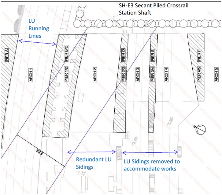
Figure 1 – Location of Lindsey Street Bridge Arches and Piers relative to Crossrail permanent works elements; ES2 inclined escalator shaft and SH-E3 secant piled shaft. 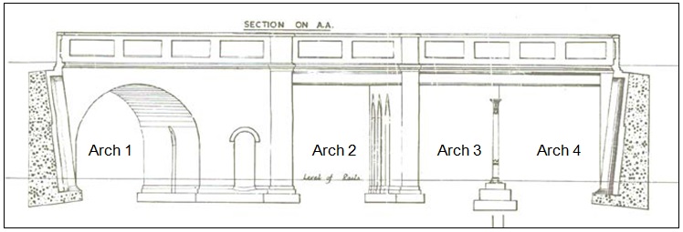
Figure 2 – Extract from historic drawing of Lindsey Street Bridge, looking east, with the original cast iron column and beam structure to the right. Within a couple of years of construction it was joined to the market building structure on the west side, and at a later date the iron structure was encased in the brick piers and arches seen today (most likely to increase its load carrying capacity). Arches 2 and 4 are semi-elliptical, and widen from west to east. Arch 3 is semi-circular (refer to Figure 3). Pier 1/2 is vaulted with an opening used for pedestrian access in the eastern façade.
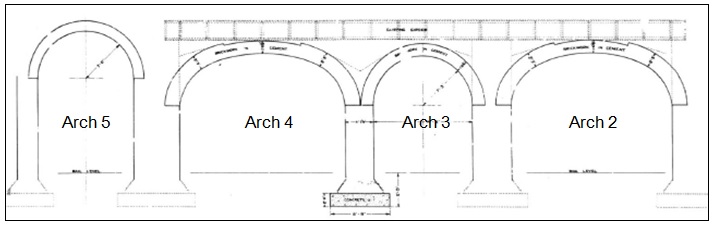
Figure 3 – Extract from historic drawing of east elevation of LSB masonry arches. Design Development
The Need for a Structural Settlement Mitigation Scheme
Total settlements greater than 100 mm, arising from numerous tunnelling operations and shaft construction in the area were predicted by the studies undertaken by Crossrail in accordance with the Crossrail Engineering Design Standard (CEDS), Part 8. These settlements would lead to distortion of the bridge and varying degrees of damage. The predicted settlement arises from three sources;
- the vertical trapezoidal secant piled shaft, SH-E3, to the east of the bridge,
- the shallow inclined escalator shaft, ES2, and
- the deep level horizontal tunnelling comprising running tunnels and subsequent SCL enlargement works.
Of particular concern was the construction of the inclined escalator shaft, ES2. This is to be mined at an angle of 30 degrees to the horizontal under two of the piers of the Lindsey Street Bridge, Pier 3/4 and Pier 1/2, with the deepest trough of settlement predicted by C122 to occur under Pier 1/2 between the Circle Line and the Moorgate Spur. As well as the risk of damage to the bridge, concerns were raised regarding the risks associated with the construction of this large escalator shaft with limited cover to the existing bridge foundations. Refer to Figure 4 for location of predicted settlement due to ES2 only and for the location of Crossrail permanent works elements relative to the bridge.
Design to RIBA Stage D by Crossrail
A conceptual design, developed to RIBA Stage D, was included in the project’s Works Information, to be developed by BFK to detailed design.
Predicted settlements and surveys of the structure’s geometry were used to predict the effects of settlement on Lindsey Street Bridge. Total settlements were predicted to be 110mm with 65mm of this due to the ES2 inclined escalator shaft alone. These settlements were later reduced to 90mm and 45mm by a reduction in shaft diameter which resulted from an architectural review.
The anticipated settlements along the faces of each pier, at various stages of construction, were used to calculate the transverse vertical curvature and tensile strains to which each pier would be subject. The resulting convergence or divergence of the piers was used to calculate the anticipated crack widths at each pier and arch. It was not clear what impact the original jack arch and wrought iron beam construction would have on the behaviour of the superstructure, following subsequent strengthening with brick arches. The Crossrail analysis assumed that the behaviour of the brickwork would dominate and so a simplified and conservative block-like action of the brickwork, as shown in Figure 5, was used.
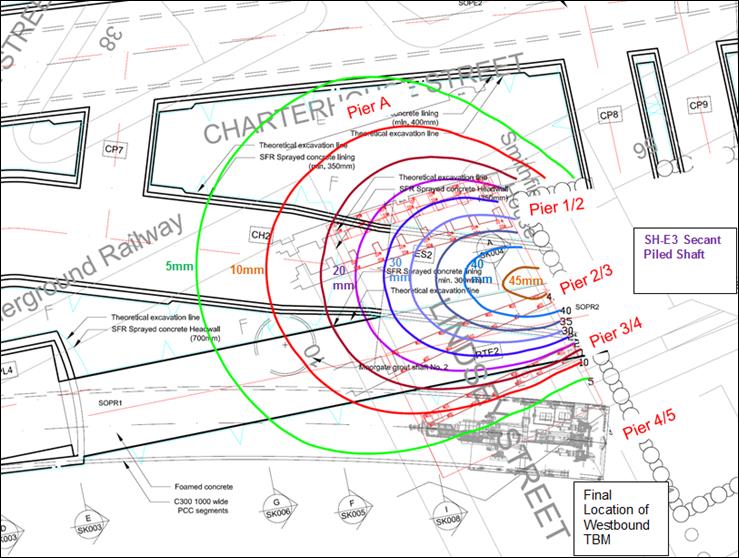
Figure 4 – Location of LSB, Crossrail Permanent Works and Predicted Settlement due to ES2. 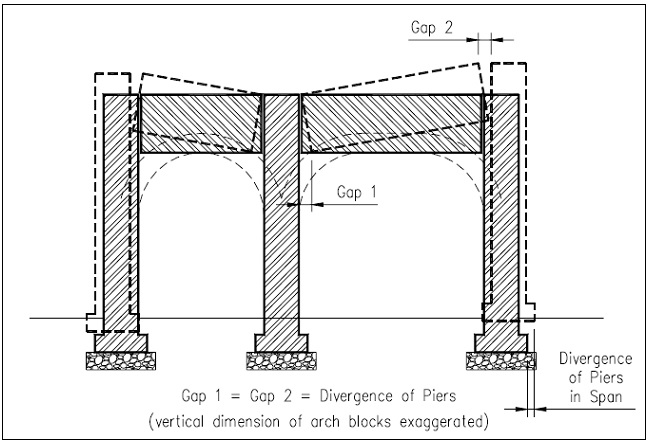
Figure 5 – Arches assumed to act like blocks as Piers diverge. It was found that these anticipated crack widths generally increased from South to North, to a maximum of 12mm at Pier 1/2. It was further established that the maximum crack width due solely to ES2 construction occurred at the same location to a maximum of 11mm. The tensile strains and crack widths calculated placed Pier 1/2 and a number of the arches in the ‘Moderate’ damage category when classified in accordance with Burland et al [1]. While this would not lead to structural failure and could be repaired, it was not considered to be acceptable to LU or to the City of London, nor would it be acceptable given the inclusion of the bridge within the curtilage of the Smithfield Market Grade II* listing.
The completed Conceptual Design Statement of the proposed mitigation measures to reduce the impact of settlement on Lindsey Street Bridge defined the major elements of the design as follows. Refer to Figure 6 for details of the final Conceptual Design.
- Piling: a 16m long wall of contiguous piles to be installed to the north of Pier 1/2 to retain the ballast supporting the LU Circle Line track during the proposed underpinning works to the bridge structure. These piles would need to be installed during LU Engineering hours.
- Underpinning: excavation for the construction of the new reinforced concrete raft foundation to be carried out in stages;
a) Cast strips (west-east) between the existing footings, with hinged capacity along the interfaces and longitudinal post-tensioning (north-south) passing through the hinges,
b) Complete the raft by casting strips between those already cast, coupling to the post-tensioning at the hinges and tensioning this on completion. - Jacking: hydraulic jacks, supporting needle beams cast through the piers, to be used to maintain the level of the bridge and to provide temporary support to the structure during the removal of the existing pier foundations and for the construction of the new raft foundation.
Scheme Development and Value Engineering by BFK
BFK and their appointed designers, Tony Gee & Partners (TGP) developed the RIBA stage D conceptual design to detailed design to reduce interfaces, ease constraints and improve ‘buildability’ of the structural solution. The completed design was defined by the Lindsey Street Bridge Temporary Works Design Statement, C435-BFK-C-XST-M123-50001. While the general philosophy of the solution specified in the conceptual design was maintained, in terms of compensating for settlement by jacking and spreading the ground pressure over a wider area by the use of an underpinning raft, significant modifications resulted from Value Engineering and Health and Safety considerations. These are summarised below, along with the benefit(s) accruing from each. Refer to Figure 7 for a cross-section through the Value Engineered BFK design issued for construction.
- The reinforced concrete raft, which forms a base footing for the jacks, to be constructed above the existing footings, rather than in place of them. This reduced the depth of excavation required.
- The raft design eliminated the hinges and post-tensioning. This simplified construction of the raft. It also eliminated concerns with regard to the effectiveness of the hinges given that the alignment of the hinges was parallel to the bridge piers, rather than to the ES2 shaft.
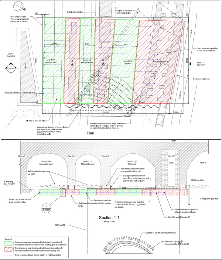
Figure 6 – LSB Mitigation Measures: General Arrangement of Crossrail Conceptual Design. - A reinforced concrete lintel was introduced within the pier walls directly above the jacks. This assured a more even spread of load onto the jacks and thus minimised the number required whilst keeping stresses in the pier masonry unchanged.
- The use of a piled wall within the live LU tunnel between wall and track was removed. Instead, the level of the RC slab, jacks and lintel were stepped up locally in Pier 1/2 North (the portion of Pier 1/2 North of the internal vaults) to above track level. This had major benefits in eliminating the need for the majority of the LU engineering hours assigned to the works. Removing the requirement tom carry out these works in a a highly constrained environment also had significant safety benefits.
- A further reduction in the LU interface was achieved by the development of a detail whereby the slab and lintel in Pier 1/2 North do not extend through the full width of the pier. Rather, a width of Pier equivalent to two brick courses is left in place on the track face, with vertical separation achieved by a steel ‘shelf’ supported from the underside of the lintel. This has the added benefit of removing any requirement to divert LU services on this face of the Pier. Refer to Figure 8 for detail.
- A bracing arrangement to resist potential accidental loads on Pier 1/2 North due to train derailment was introduced following discussions with LU.
- Lateral restraints were provided from all pier bases to above jacking level to resist arch action lateral thrust forces.
- The uncertainty in the portion of load carried by the old cast iron portion of the structure was addressed by introducing clamps to the bottom of the cast iron columns in Pier 3/4, such that the columns were shear-connected into the RC lintel in the pier. The columns were then cut below the clamp to permit vertical movement in line with the jacking operation. A subsequent intrusive camera survey revealed that the historic cast iron beams which are supported by the embedded Pier 3/4 columns are heavily corroded, indicating that the steel elements that remain within the existing structure no longer carry significant load.
- The active load transfer into the supporting slab by means of post-tensioning the hinged raft in the conceptual design was removed in favour of passive load transfer by means of raft slab deflection in response to settlements in the ground beneath.
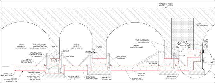
Figure 7 – BFK Detailed Design Solution for Lindsey Street Bridge Settlement Mitigation. 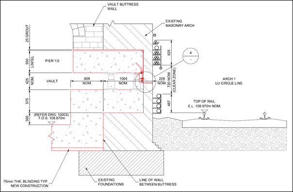
Figure 8 – Detail through Pier 1/2 North; steel shelf supporting two courses of brickwork. Design Loads
Masonry arch bridge assessment software was used to determine vertical loads and lateral thrust forces in the structure at various stages of construction. The outputs of this analysis were used to design the hydraulic jacks, supporting steel stools, and the lateral restraints to the piers (all detailed in Figure 7).
The design of the structural mitigation works needed to take account of the variation in loading on the underpinning slab resulting from the mining of the ES2 shaft beneath. Such impacts were studied by conducting a 2D soil spring analysis of the raft with reduced spring stiffness assumed in the vicinity of ES2 to reflect softer soil supports in this area. Based on the results of this analysis, the raft was designed to redistribute loads such that it deflects , increasing loads on either side of any ground settlement, smoothing the overall settlement profile. Thus strength is the key design consideration for the raft rather than stiffness.
Conversely, the design and construction methodology for the sprayed concrete lined ES2 shaft needs to take account of the loads from Lindsey Street Bridge. A similar 2D soil spring analysis was carried out to establish the ground pressure distribution resultant from original pier loadings plus raft dead loading prior to any load redistribution. This conservative load case was used in the temporary and permanent works design of the ES2 tunnel.
Construction and Installation Works
Underpinning Lindsey Street Bridge brought about a unique set of challenges, which included overcoming the logistical constraints imposed by live construction sites on either side of the bridge, and extremely confined working areas.
Piers 1/2 South, 2/3 and 3/4
The breakout of the piers, in accordance with the approved design, was carried out using work methods chosen as appropriate to the constraints on access, and the risks associated with railway interfaces. On piers 1/2(south), 2/3 and 3/4, wire saw cutting was used to define the boundaries of the sections in which the piers were removed as specified by the design.
The breaking out was done using a remote-controlled demolition robot, selected for its compact size and manoeuvrability in limited space. A major health and safety benefit of the use of this item of plant was the reduction in the use of hand held breakers. This mitigated the risk of injuries resulting from localised masonry collapse as well as significantly reducing the exposure of operatives to hand-arm vibration. This process of wire saw-cutting and breaking was repeated for the installation of the RC lintels and the creation of the jacking zone space between the raft and lintels.
Figure 9 presents photos of various stages of the construction process as follows;
9a. remote controlled demolition robot breaking 900mm wide sections from masonry in ‘hit and miss’ sequence,
9b. masonry breakout propped with steel stools which are cast into the works,
9c. preparing to cast underpinning slab in Arch 2 (slab already cast through Pier 2/3),
9d. underpinning slab and lateral propping complete in Arch 3, looking east.
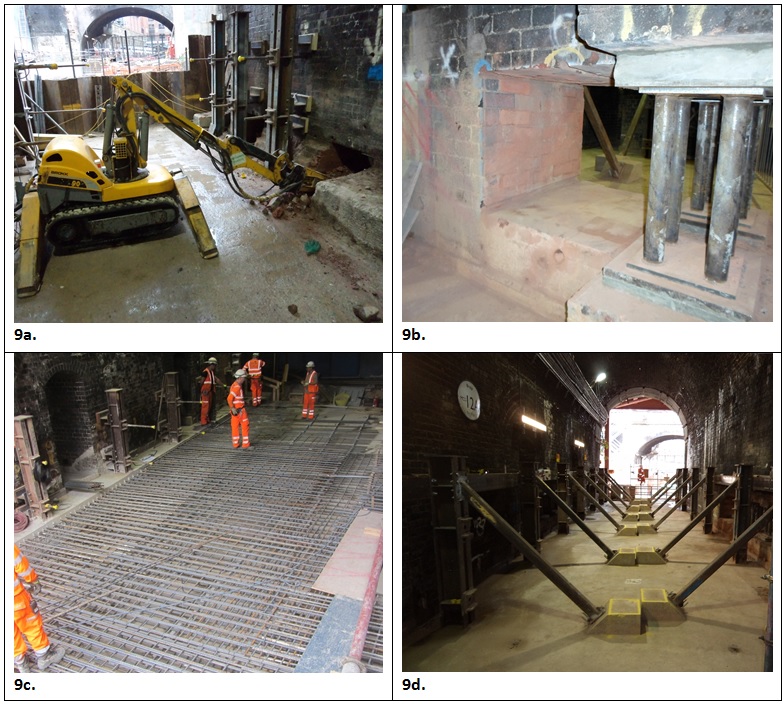
Figure 9 – Masonry breakout, propping and RC works on Piers 1/2 (south), 2/3 and 3/4. Pier 1/2 North
A modified construction method was required to install the lintel and stepped portion of the slab through the northern portion of the vaulted pier 1/2 as this element forms the boundary with the live LU lines. The requirement to break out this brick pier to within approximately 200 mm of live power cables and a live train line was identified as a major risk. BFK engaged with LU from an early stage of the design process and throughout the construction phase, through regular meetings and site visits, to ensure this key stakeholder had confidence that their critical assets were appropriately safeguarded throughout.
As wire saw-cutting and the use of a mechanical breaker were not feasible due to the confined space available in the vaults an alternative method of keeping close control of the operation to avoid overbreak was required. This was achieved by coring a series of 100mm diameter holes to the required depth. The brick that remained was then broken out using lightweight pneumatic hand breakers.
Figure 10 presents photos of various stages of the construction process as follows;
10a. masonry coring used to control extent of breaking at railway interface,
10b. masonry breakout for lintel with expanded metal panels installed ahead of casting concrete to ensure no concrete pressure on the 200mm wide masonry section,
10c. preparing to cast underpinning slab in Pier 1/2 vaults (step in slab visible),
10d. Structural works completed in Pier 1/2 vaults, ready for installation of hydraulic jacks.
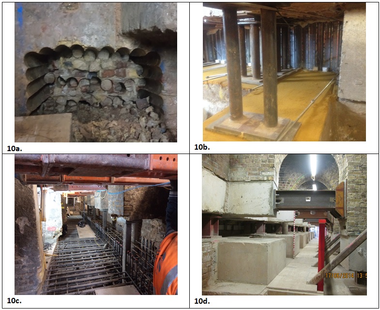
Figure 10 – Masonry breakout, propping and RC works on Piers 1/2 (north). Structural Assessment and Development of Revised Movement Trigger Values
The C435 Farringdon Works Information defined a generic Amber Movement Trigger Value, on all structures within the compensation grouting zone, as a slope of greater than 1:1000 on any part of the structure. BFK monitored movement against this specified value during installation of the structural mitigation works but commissioned a structural assessment as a means of defining structure-specific movement triggers based on the capacity of Lindsey Street Bridge to accommodate movement.
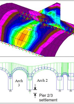
Following the completion of a condition survey on site, 3D finite element analysis of the arches found that the load path from the original jack arches to the newer reinforcing arches could be representatively modelled as a 2D problem. Combinations of settlement between and along piers were applied to the 2D model which was then analysed to identify the strains induced in each arch and pier of the structure. Figure 11 presents examples of the modelling carried out.
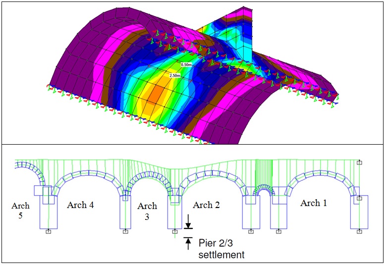
Figure 11 – 3D finite element and 2D arch modelling of Lindsey Street Bridge. For each arch the applied differential settlement between piers was plotted against the maximum resultant tensile strain in the arch. Where the resultant strain entered the severity category defined as Slight, or 0.075%, by Burland et al [1] the corresponding differential settlement value was used to define a revised ‘Amber’ Trigger Value which if exceeded would lead to defined actions including a full review of recorded movements and construction methods. As can be seen from Figure 12, the Trigger Values, or amounts of pier settlement which the structure can accommodate before entering the Slight damage category, are proportional to the span of the arches on either side.
These trigger values are defined as the settlement of a particular pier relative to a datum formed by taking a line between the piers on either side. The new triggers were agreed with City of London and LU, as to be applied during the critical ES2 shaft mining works.
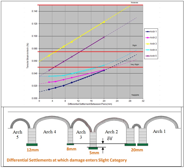
Figure 12 – Differential Settlement between piers plotted against resultant tensile strain, and used as movement trigger values. Monitoring Movements
Monitoring of the structure for any movement, during the course of the works, formed a crucial part of the scheme. In order to ensure sufficient control of the works and understanding of the impact that tunnelling, grouting and jacking has on Lindsey Street Bridge, a variety of monitoring methods were employed.
Instrumentation and Monitoring
Movement of Lindsey Street Bridge continues to be measured and recorded by two monitoring systems. Refer to Figure 13 for schematic arrangement of monitoring points on the structure.
- An automated system using Automated Total Stations (ATS) with 3D Geodetic Prisms, provides hourly 3D readings of monitoring points located on the piers and arches. This data is relayed to the BFK monitoring database within three hours of the reading being taken.
- To complement and verify the automated system, BFK manually monitor the BRE sockets fixed to the structure.
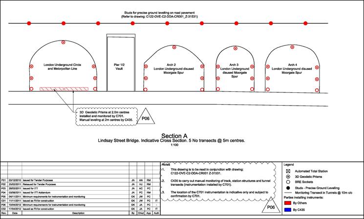
Figure 13 – Schematic of monitoring devices in place on Lindsey Street Bridge. Differential movements between the underpinning slab and the supporting ground below are not anticipated by the design, as the slab has been designed to deflect to the profile of the ground after settlement, but were they to occur, they could have major implications for the stability of the structure. Automatic Shape Accel Arrays (SAAs) have been installed in the slab (perpendicular to the piers) and in the ground beneath the slab (generally parallel to the piers). Refer to Figure 14 for the alignment of these instruments relative to the bridge and slab structure). These instruments consist of a string of triaxial MEMS gravity sensors at 500mm centres, providing real-time information to a high level of precision about how the ground beneath the slab is reacting relative to the slab itself. Differential movements between these instruments at their crossing points would indicate the development of a void beneath the slab. Vertical tubes have been cast into the slab at regular intervals in order to provide a means to fill any voids that may develop with cement grout.
Ground Movement Action Plan
The procedures and protocols for managing and controlling ground movements throughout the construction of the mitigation works described and during the construction of elements of the permanent works that impact on the bridge, such as the ES2 Escalator Shaft, are specified in a structure specific Ground Movement Action Plan. This document, produced by BFK in consultation with the relevant stakeholders, including LU and City of London, prescribes specific actions to be taken in response to defined movement Trigger Values. The Action Plan specifies how these actions should be carried out, including defining the parameters within which mitigating actions such as grouting or jacking must operate, and prescribes lines of communication to be followed between the relevant parties.
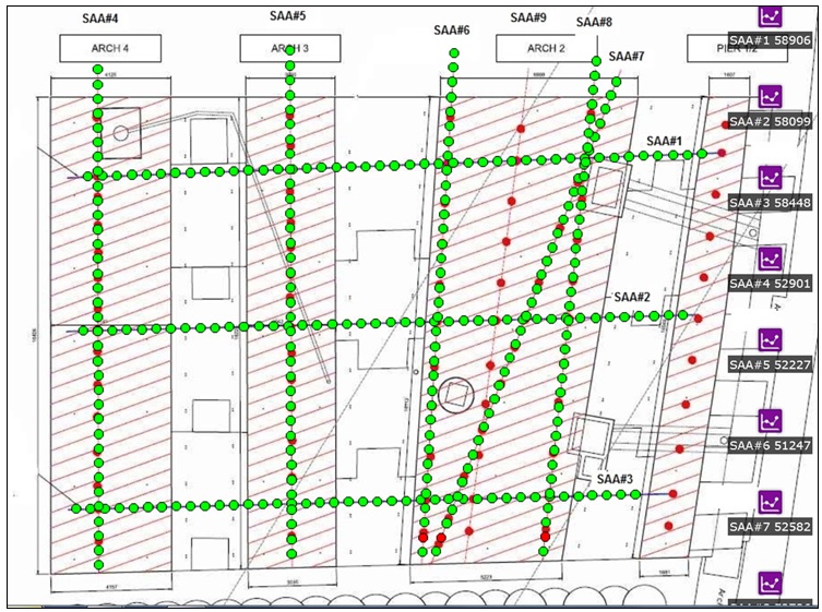
Figure 14 – Alignment of SAAs relative to Lindsey Street Bridge: individual MEMS sensors in green, ‘manual verification points’ in red. Trigger Values
To provide a graded warning system, the Action Plan also specifies Green and Red movement triggers with values defined as 75% and 125% of the Amber values defined by BFK respectively. Table 1 shows the Trigger Values thus adopted by BFK on differential settlements between piers for the control of all construction works with the potential to impact the structure. Trigger Values are similarly specified for slopes along the piers, and for voids beneath the slab recorded by the SAAs.
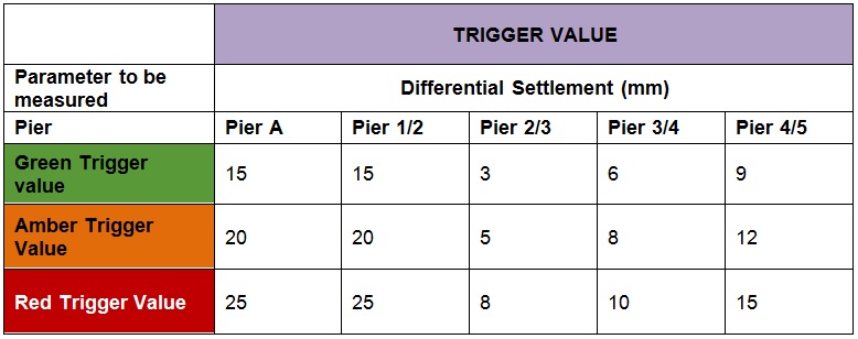
Table 2 – Lindsey Street Bridge: Specified Differential Settlement Movement Triggers Actions in Response to Movements
The mitigating actions available upon breach of a Trigger Value are defined in the Action Plan. These actions are designed to ensure that the structural integrity of the bridge is maintained at all times and that relevant stakeholders are kept informed of how construction works affect the bridge. The primary corrective action during the construction of the most critical item of permanent works, ES2, is the hydraulic jacking of the bridge itself. When a decision to jack is taken, based on the monitoring results, the Action Plan requires that a ‘Jacking Proposal’ based on these movements be produced. This proposal will define the corrected level to be achieved at each jacking location, and an incremental jacking sequence to be used to achieve these levels. All jacking proposals are to operate within the following parameters;
- Each episode of Jacking must not move any part of the structure by more than ±5 mm,
- A jacking ‘episode’ will include a number of ‘passes’. The maximum movement of one pair of jacks in one pass will be ±1 mm,
- The maximum load on any jack at any point during a jacking episode will be limited to 120% of the load recorded on the jack prior to the commencement of the episode (and not exceeding the jack capacity),
- The maximum stroke differential between any two adjacent jack pairs on the same pier at any point during a jacking episode will be 1mm.
Given that the three piers underpinned by the RC slab only represent a portion of the structure which extends to the north (over live rail lines), south and east, compensation grouting will typically be used in tandem with hydraulic jacking to ensure differential settlements are adequately controlled over the full extent of the structure. Where a corrective proposal includes the requirement to carry out compensation grouting as well as jacking, the compensation grouting episode will generally be carried out first, in the areas outside of the SCL grouting exclusion zone (minimum 3m radial from tunnel excavation), and the impact on the structure assessed prior to the implementation of the related jacking episode.
Mitigating Movements through the Use of a Synchronised Hydraulic Jacking System
The hydraulic jacks to support Lindsey Street Bridge during ES2 shaft construction will be operated by means of a Synchronised Hydraulic Lifting System. This system is made up of a Hydraulic Control Unit which electronically measures jacking parameters (load and extension), and uses these measurements to implement pre-programmed jacking sequences within defined parameters. Loads on each jack are recorded via hydraulic pressure transducers while jack extensions or retractions are recorded via Linear Variable Displacement Transducer (LVDT) sensors. Solenoid valves are used to electronically control hydraulic flow rates. A touchscreen interface allows for the display of current jacking parameter values, the setting of upper and lower bound limits, and the programming of jacking sequences by the user. The advantages of such a synchronised jacking system are summarised as;
- completion of a jacking episode is significantly quicker than the manual implementation of same, allowing for faster mitigation of settlements,
- less scope for human error in the operation of the jacks, and significantly less labour,
- more refined control, limiting the strains on the structure and the variance in jack loads that can result from an incremental jacking operation.
Refer to Figure 15 for a schematic layout of the jacking solution.
In order to ensure control of any jacking required during the course of the works, the automated jacking system incorporates an automated cut-off system comprising three aspects as follows:
- Limit based on load: The jacking system will be programmed with load limits based initially on the capacity of the jacks. The system will automatically cut off should the load limit be breached at any pair of jacks during an episode.
- Limit based on stroke differential between two adjacent pair of jacks: The jacking system will be programmed to limit the stroke differential between two adjacent pairs of jacks on any one pier to 1mm at all stages of a jacking operation.
- Limit based on targeted displacement: The system will automatically isolate jacks that have reached their target displacement. Jacking cycles will continue until the remaining jacks have also reached their targeted displacement.
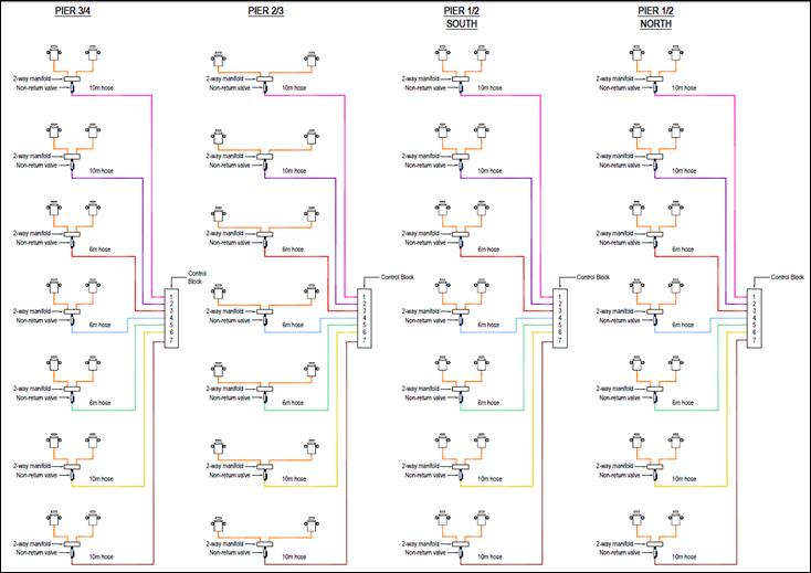
Figure 15 – Schematic Layout of Lindsey Street Bridge Hydraulic Jacking System. Conclusions
Value Engineering as part of the design development led to significant improvements in the structural settlement mitigation scheme for the historic Lindsey Street Bridge.
The use of masonry breakout methods appropriate to the structure, particularly at the railway interface ensured the risks inherent in such works were controlled.
The structural mitigation scheme was designed such that it can be used in tandem with compensation grouting.
The completion of a structural assessment allowed for the calculation of movement alert trigger values specific to Lindsey Street Bridge.
The use of a variety of monitoring systems, including electronic SAAs in the inaccessible areas under the slab, and a detailed Ground Movement Action Plan provided further assurance as to the stability of the structure.
The use of an electronically synchronised hydraulic jacking system in the design allows for a high degree of control on the level of the structure during the construction of the Crossrail works.
References
[1] J.B. Burland and C.P. Wroth. (1975). Settlement of Buildings and Associated Damage. Building Research establishment Current Paper – Building Research Establishment, Watford.
-
Authors

Jim McCarthy - BAM Ferrovial Kier
Assistant Design Manager
