Lord Hill’s Bridge Mitigation Works
Document
type: Technical Paper
Author:
Aodhán Reaney BSc, Thomas Moore HND, Brendan Bradley MEng (Hons), Jaime Sevilla BEng, Daniel Callaghan BSc (Hons), ICE Publishing
Publication
Date: 03/11/2014
-
Read the full document
INTRODUCTION
Critical mitigation works were required at LHB prior to the passage of the TBM’s to minimise settlement of the bridge structure. Not only were the planned works complex due to the location and structure of the bridge but they also had to be completed to a challenging programme, to avoid delay of the TBM’s launch.
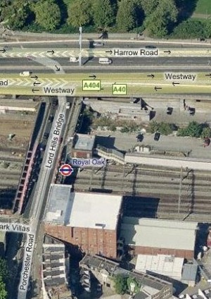
LHB is an NR asset which is over 100 years old and situated 50 m east of Royal Oak Portal (ROP). Beneath the bridge passes the NR main line tracks and LU Hammersmith and City line tracks, whilst the entrance to the LU Royal Oak station is situated on the central pier of the bridge, see Figure 1. The proposed Crossrail tunnels pass under LHB at shallow depth due to the constraints on positioning ROP. The portal is bound by NR & LU assets on the south, Harrow road wall to the north, LHB / Ranelagh Bridge and Westbourne Bridge to the east whilst sufficient room was required to the west of the portal to allow space for the logistics of a tunnelling operation and the final operational railway.
Crossing the bridge is a 600 mm steel gas main, twin 450 mm water mains and twin 66kV power cables. The bridge construction consists of a two span simply supported structure with a fixed central bearing and two outer guided bearings. The outer guided bearings are situated on top of masonry brickwork abutments which in turn are situated on a concrete footing spread foundation, as is the central pier foundation. Both spans of the bridge consist of two steel truss main girders with the road and footpath supported on under slung steel cross girders. The north span of the bridge is 27 m in length and the south side is 44.5 m in length.
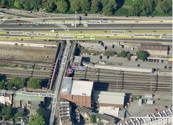
Figure 1 – Lord Hill’s Bridge Location.
The foundations of the bridge are founded upon London clay which is situated a couple of meters below the ground level. Above the London clay is a layer of Alluvium and made ground. Adjacent to the north abutment was an area of existing Brunel foundations.
Due to the deteriorating condition of the bridge restrictions were implemented in 2003 to limit the number of vehicles crossing the bridge, this was achieved by reducing the bridge from three lanes to two with the introduction of a central reservation. Further assessments in 2005 by Westminster County Council (WCC) highlighted that the bridge showed signs of further deterioration and it was recommended that the bridge be rebuilt within 4 years.
DESIGN
Predicted Movement
The C300 western running tunnels running from ROP to the east side of Farringdon station are being constructed using two Earth Pressure Balance (EPB) TBM’s. The TBM’s passed beneath LHB barely 4.0 m below the ground surface and with less than 3.0 m clearance to the North Abutment during construction of the E/B drive.
Due to the shallow nature of the tunnels below LHB an assessment of ground movement effects as a result of tunnel construction was undertaken. The ground movement assessment was based on greenfield ground movements and modelled on a volume loss of 1.0 % from the bored tunnelling works. The assessments gave max vertical displacements of 32.6 mm at the north abutment footings with corresponding horizontal movements of 10.8 mm with a maximum differential settlement of 28 mm.
LHB foundations were modelled based on the aforementioned greenfield settlement values and the following assumptions:
- The bridge abutment was modelled as a linear elastic rectangular beam.
- It was assumed that the calculated horizontal strains were transferred directly to the structure being assessed.
- Induced ground strains are based on a greenfield approach, i.e. no stiffness was attributed to the foundation, and bridge loads were not included.
Due to the predicted differential settlement at the footings it was envisaged that the North Abutment would tilt towards the central pier and thus increase horizontal movements on the North Abutment bearings. The calculated movements at bearing level were; 58 mm horizontally and 26 mm vertically.
The poor condition of the bridge, meant it had limited capability to accommodate further horizontal movement at the North Abutment. Visual inspections of the bearings at the North Abutment indicated that the bridge could likely accommodate 34 mm horizontal movement (if a movement joint was installed on the bridge deck).
Structural assessments also indicated that the bridge could accommodate settlement of up to 50 mm and differential settlements of up to 30 mm.
As the bridge was considered to be able to accommodate 34 mm horizontal movement and movements of 58 mm were expected it was proposed that a mitigation scheme was put in place to minimise the impact of tunnelling on the bridge structure.
Mitigation Proposals
The first proposal for mitigation works was termed Option A, (Appendix 1 drg no: C122-OVE-S-DDB-CR001_Z-42003). Option A involved constructing 1800 mm dia mass concrete piles with 600 mm dia concrete infill piles across the area of both the eastbound and westbound tunnels, including up to 10 m either side of the east and west flanks of LHB. The 1800 mm dia piles were intended to be installed to a depth of 1 m below tunnel invert level with further inclined piles installed below the north abutment. It was intended that the piles would be used as a form of ground replacement.
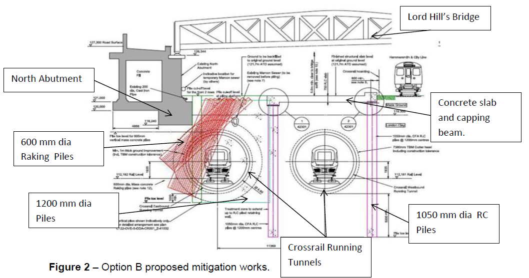
After consultation between the designer (C122), contractor (BFK) and Client (Crossrail) the mitigation works were refined to Option B, (Appendix 2 drg no: C122- OVE-S-DDB-CR001_Z-42031). Option B works consisted of mass concrete piles placed above the eastbound drive to tunnel invert depth, and raking piles installed below the north abutment, see Figure 2. A further two rows of reinforced contiguous piles were planned for either side of the westbound tunnel with a reinforced concrete capping beam to act as a prop across the two rows of piles. The raking piles were designed to fully encapsulate the eastbound running tunnel, whilst the slab above the westbound tunnel was implemented to prevent uplift should the TBM be operating at a pressure greater than overburden.
It was anticipated that during construction works ground movement would be caused as a result of installation of the piles and reduction of the ground level. As part of the Option B mitigation works there was a requirement to reduce the ground level below the bridge, this created the required 5 m of headroom for the piling rigs to construct the mass filled concrete piles.
A number of considerations to the works on site were suggested by the designer to ensure that ground movement was kept to a minimum, they included:
- No adjacent piles were to be built until the previous piles had achieved the stiffness and strength of the ground. It was therefore stipulated that adjacent piles would not be installed within a 72 hour time frame. Sequencing was of paramount importance – especially for the raking piles under the North Abutmen
- Temporary casing was to be installed to support the upper section of the pile in the made ground during construction.
- Piles were to be backfilled with concrete as soon as excavation and spoil clearance was complete.
- During piling platform construction, bay widths were not to exceed 4 m in width.
- Piling on the outer flanks was to be carried out with a CFA (Continual Flight Auger) piling rig to reduce ground settlement.
Ground Settlement Predictions Post Mitigation Works
Once a design for mitigation works had been agreed, ground settlement predictions were run for a second time to establish predicted movements due to tunnelling.
The resulting movement predictions at bearing level of the North Abutment gave values of < 1 mm horizontally and 2 mm movement vertically, and movements at the central pier of < 1 mm horizontally and 8 mm vertically.
The combination of settlement due to tunnelling and settlement due to undertaking the mitigation works was combined and gave predicted movements for the bridge post passage of both TBM’s – Table 1.
Location North Abutment Central Pier Stage Of
Construction
Max.
Horizontal Movement (mm)
Max. Vertical
Movement
(mm)
Max.
Horizontal Movement (mm)
Max. Vertical
Movement
(mm)
Mitigation
Works
<3 <3 <3 <3 Tunnelling <1 2 <1 8 Total <4 <5 <4 <11 Table 1 – Predicted ground movements post TBM passage
A design was produced for a movement joint on the north side of the bridge should excessive horizontal movement be recorded.
Utility Diversions
Utility diversion works were required as they essentially removed the risk of the existing mains being damaged, due to settlement induced by piling and subsequent tunnelling activities. This was achieved by replacing the existing utilities which were in a very poor condition and replacing them with new diversions which acted independently of the bridge structure.
Assessments based on a 0.5% volume loss indicated that mitigation works were required on the existing 600 mm steel gas main which crossed the bridge on the west side. A number of proposals were considered with the final solution consisting of a 450 mm HDPE replacement main running across the bridge deck and being connected to the existing gas main behind the north and south abutments.
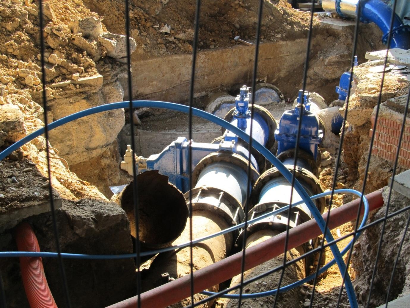
On the east side of the bridge is located two 450 mm water mains encapsulated in a steel box conduit. Mitigation works were required as assessments indicated that there was the possibility of inducing excess strain in the pipe, this was most prevalent at the intersection between the North Abutment and bridge deck. For these reasons it was decided that a 300 mm steel rider main was to be constructed and placed on top of the bridge deck on the east side. Connections were to be made on the north and south side of the bridge into the existing main, see Figure 3.

Figure 3 – North Abutment rider main connection – looking south.
The final utility crossing the bridge was a 66 Kv cable situated under the footpath on the east side of the bridge. Assessments indicated that the cable would be unaffected by ground movements and that induced strain in the cable would be negligible. For these reasons it was decided to install monitoring in a cable joint bay on the north side of the bridge to closely monitor for un-expected movements.
All of the aforementioned diversionary works were subject to an intense public interface, as the entrance to the LU Royal Oak station is situated at the centre of LHB. In addition to the location of the station, road and footpath closures were required to facilitate the diversion works.
CONSTRUCTION
Pre Piling Works
Before any of the main works could commence at LHB there were a number of work activities that had to be completed; these consisted of removal of old Brunel foundations from underneath LHB, construction of a piling platform and the removal of the Marcon sewer that ran through the area which was to be piled. The Brunel foundations were removed under a strict sequence due to the depth of the excavations underneath LHB. The piling platform was constructed using imported recycled type 1, depth of which reached 800 mm at times. The Marcon sewer, an old Victorian sewer which ran the length of the site was removed using a proprietary drag box system, as the brick sewer was in close proximity to the bridges North Abutment.
The main constriction with the piling works was the low headroom under the bridge, for this reason the piling platform was constructed at a lower level than original ground level. The platform was constructed to give the piling rigs 5.1m clearance, which was the minimum required by Keller/Martello (the piling subcontractor) who modified their rigs to suit the restricted clearance. In addition to the low headroom issue, a great deal of attention was paid to the London Underground Hammersmith and City Line, which was only 3 m from the piling area. This required close liaison with LU on a weekly basis to ensure the works did not have an adverse effect on the LU assets, due primarily to settlement being caused by the piling activities.
Piling Beneath LHB
The first piles consisted of 1200 mm vertical mass filled concrete (MFC) installed by the restricted headroom Martello rigs, see Figure 4. These were installed using a 3.5 m long casing; the reason for the casing was to give a seal into the London clay to prevent ground water entering the pile during excavation. A strict sequence was incorporated for these piles, which entailed installing 1, missing 3 and not piling adjacent piles for 72 hours. The sequencing was carefully planned by the site team with forecast drawings being produced to ensure that the restrictions with installation were met. On a daily basis these sequence drawings were as built to confirm that the correct sequence was completed.
For tunnelling purposes the strength of the concrete in the piles needed to be less than 10 N/mm² but more than 4 N/mm². The reason for the upper and lower bound concrete strengths was to ensure that the mitigation works provided an effective mitigation to ground movement during tunnelling but didn’t prove an obstacle to tunnelling beneath the bridge. Due to the required characteristics of the concrete strict quality control by the concrete supplier and the site team was required to ensure compliance to the specification. The concrete had no coarse aggregate and contained either 80% or 90% PFA to meet the required specification, as well as being designed to be easily pumpable from the on site re-mixer to the pile location. Due to the strict parameters & unusual mix requirements of the concrete strength there were issues with conformity and a number of piles achieved a higher strength than required. Due to a strict quality control regime enforced and managed by the site team the high strength concrete piles could be easily identified, removed and replaced to ensure all works were compliant with the specification.
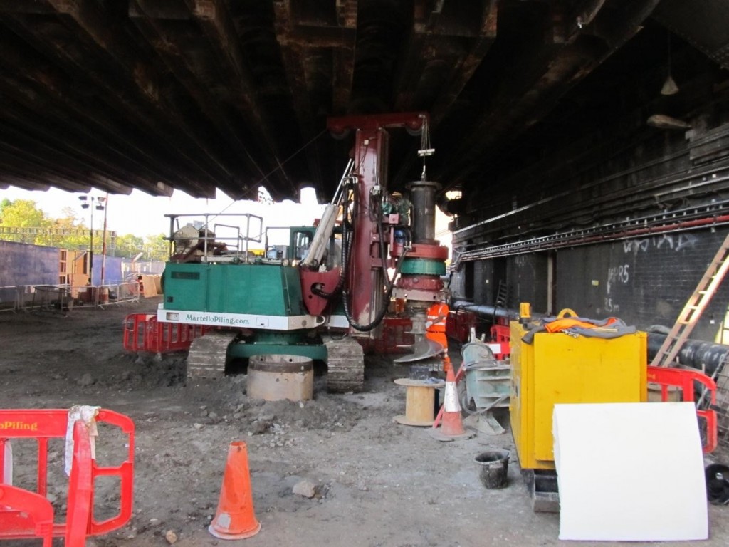
Figure 4 – Martello 5000 Series low headroom piling rig working beneath LHB.
Issues with ground water also became apparent upon boring 1200 mm dia piles near the bridge abutment, which was caused by an existing drainage system from the Harrow Road retaining wall. Due to the presence of the water the site team were unable to obtain a seal into the clay, which is required to prevent water ingress into the bored excavation. The site team proposed and implemented a solution which entailed installing a 1050 mm dia pile in the area affected by water. This enabled a longer casing to be installed, thus providing a sufficient seal into the clay as required.
Simultaneous to the 1200 mm dia piles the 900 mm and 1050 mm dia piles were installed around the area of the Marcon sewer. Due to the presence of backfill from the removal of the existing Marcon sewer an outlet had been formed for water from the surrounding made ground to drain into, this meant that the 3.5 m casings used for 1200 mm dia piles were not long enough to provide a seal into the clay in the area of the existing sewer. Smaller diameter piles were used to enable segmental pile casings to be installed which would ensure a suitable seal into the clay, casings ranged from 3.5 m to 5.5 m in depth. Due to the low headroom under the bridge there was great difficulty in manoeuvring the casings, a mini crane was used for lifting and manoeuvring the casings. The CFA rig installed the 600 mm piles on the flanks of the bridge and the reason for these was to infill the areas that were not covered by the larger piles. The sequence for the 600 mm piles allowed 48 hours between each pile, again the concrete used had to provide strength of less than 10N/mm².
The reinforced piles and the slab was the next phase of works which essentially created an underground portal for the westbound TBM to pass through. The piles flanking the slab were 1050 mm reinforced concrete (RC) piles. Due to the minimal clearance underneath the bridge the rebar cages needed to be installed in 5.0 m sections (Figure 5) and spliced together in situ, once in place C32/40 concrete was then placed to form a 1050 mm RC pile. The reinforced concrete slab and capping beam were poured in 2 sections, the first section was against the Asset Protection Barrier (APB), which was in place to form a physical barrier between the C300 site and LU assets. Excavating close to the APB was difficult as the dig was approx 1.5 m in depth and in close proximity to the LU track; therefore requiring a temporary ACROW propping system to support the APB during excavation and construction works, see Figure 6. A strict programme for these works were in place with only 2 weeks to complete the construction capping beam, this was achieved through working extended hours and utilising 2 shifts to complete the works on time. Upon completion of the capping beam along the APB the temporary props were removed and the main RC slab was constructed using 32 mm dia and 30 mm dia reinforcing bar. Once all the rebar and formwork shutters were fixed for the slab, 400m3 of C32/40 concrete was pumped into the area to complete the RC slab.
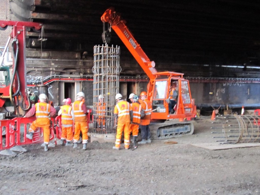
Figure 5 – Mini crane lowering 5.0 m reinforced cage in 1200 mm dia pile under LHB.
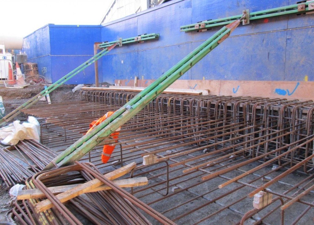
Figure 6 – ACROW props supporting APB as capping beam reinforcement is placed.
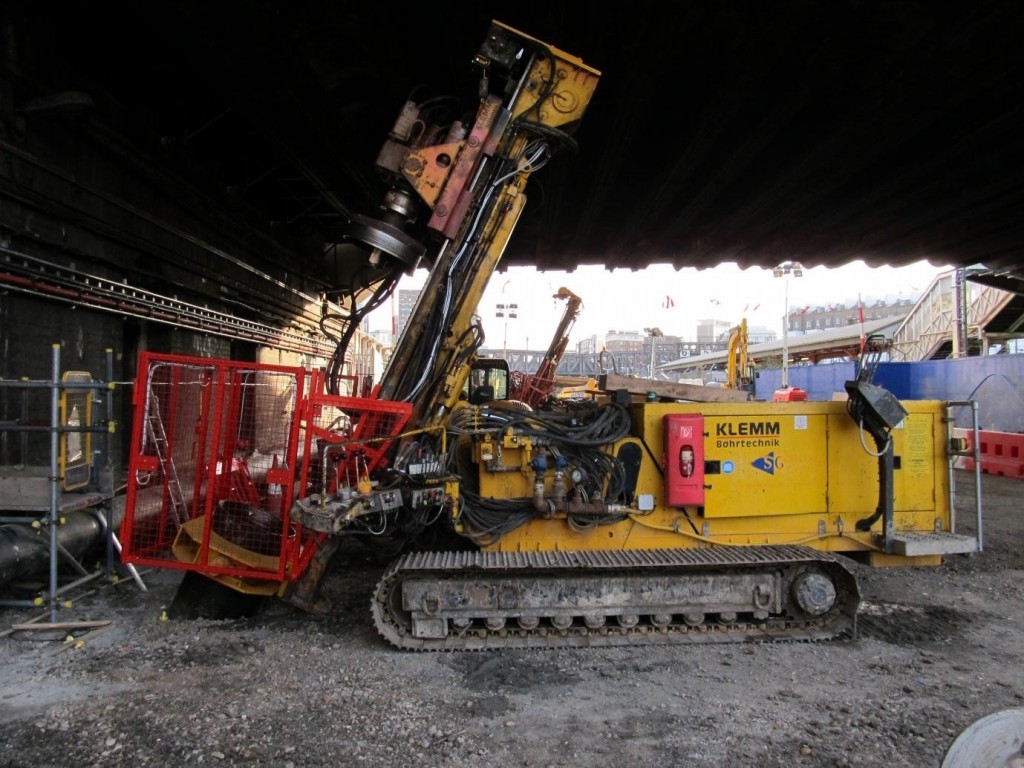
Figure 7 – Klemm 709 piling rig installing raking piles below LHB.
The raking piles were the last piles to be constructed and 3 specialist KLEMM piling rigs were utilised, see Figure 7. A total of 597 raking piles were installed with a very stringent sequence – 72 hours between piling an adjacent pile. The reason the sequence was so stringent was that the piles were directly beneath the North Abutment foundations and there was a high risk of settlement. Leaving the pile open for a period of time before concreting was considered unacceptable, as there was a potential for settlement to occur, for this reason piles were concreted immediately upon completion of boring. The sequence was changed a number of times to ensure maximum efficiency for the installation of the piles along with minimising the risk of settlement. The piling rigs were modified to allow for working within the restricted headroom of the bridge and the site team also fabricated special gates around the auger area of each rig to keep operatives away from the moving parts.
Tolerances constructing the piles were as follows – horizontal ±75mm and vertically 1:75. All tolerances were met through a stringent and proactive quality control procedure established on site, with every pile checked at setting out stage and when the casing was installed.
The highest daily output recorded from pile installation was 25 in one day, this was in part achieved thanks to a well planned site layout. Coordination between the different construction teams allowed the ever changing interface of the piling activities to run smoothly, as at times there were up to 5 piling rigs working in close proximity to one another.
All key dates/milestones were met, with works completed 1 week ahead of programme – Figure 8. All of the aforementioned was achieved due to the good working relationships on site and with no compromise to safety, quality or the environment.
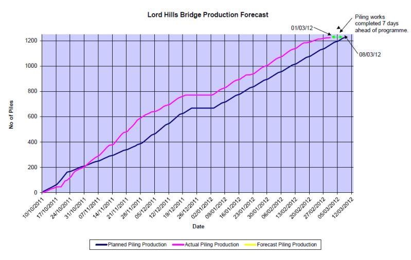
Figure 8 – Graph of planned vs actual piling production.
LORD HILL’S BRIDGE MONITORING
In accordance with the Assessment of Ground Movement Effects for LHB, an observational approach was implemented to monitor the piling construction works and subsequent tunnelling works.
Installed Monitoring
Many different types of monitoring instruments were used on LHB and the associated assets – Table 2.
Instrument Quantity Location Purpose 3D Geodetic
Prism
10 North Abutment (2
Rows of 5No.)
To provide horizontal displacements and Rotation or Tilt 3D Geodetic
Prism
12 Girders (both Main
and Tertiary)
To provide horizontal displacements for bridge deck compression 3D Prism 8 Central Pier (North
side)
To provide horizontal
displacements and Rotation or Tilt
BRE type
Levelling Studs
5 North Abutment Precise manual levelling Invar Levelling strips 4 Central Pier Precise manual levelling RVDT 3 North Abutment/Tertiary
Girders
Rotational movements of the north abutment from the deck HLC
(Hydrostatic
Levelling Cells)
4 North Abutment Real time precise levelling Crackmeter 1 UKPN Cable Joint Differential movements between joint and cable Strain Gauges 3 NGG Gas main Accurate monitoring of the old gas main PLPs Many Bridge deck and off North Abutment Precise levelling of the bridge deck and ground behind the bridge. Table 2 – Summary of instrumentation installed on LHB.
In addition to the minimum I&M requirements, hydrostatic levelling cells (HLCs) were installed on the North Abutment to provide real-time and extremely precise settlement readings. This allowed the monitoring engineers to gain a more complete understanding of how the piling works affected the structure.
Monitoring of the works was reviewed during the Shift Review Groups (held for each shift), during which the monitoring data would be reviewed and discussed along with the construction works. By bringing this information together during each shift, the SRG (made up of a construction representative, an engineering representative, the designer and the client) could determine the most appropriate way forward with regards to sequencing of works so as minimise movements caused by the works.
Expected Ground Movements
The Assessment for the Control of Ground Movements for Lord Hill’s Bridge concluded that no more than 3mm (both Horizontal and Vertical) of ground movements should occur as a result of the installation of the mitigation works. Based on expected ground movements a number of trigger values were set.
Trigger Values
Trigger values on Lord Hill’s Bridge were set based on the expected movement from the Assessment. Table 3 shows the Trigger Value originally set prior to the commencement of the works.
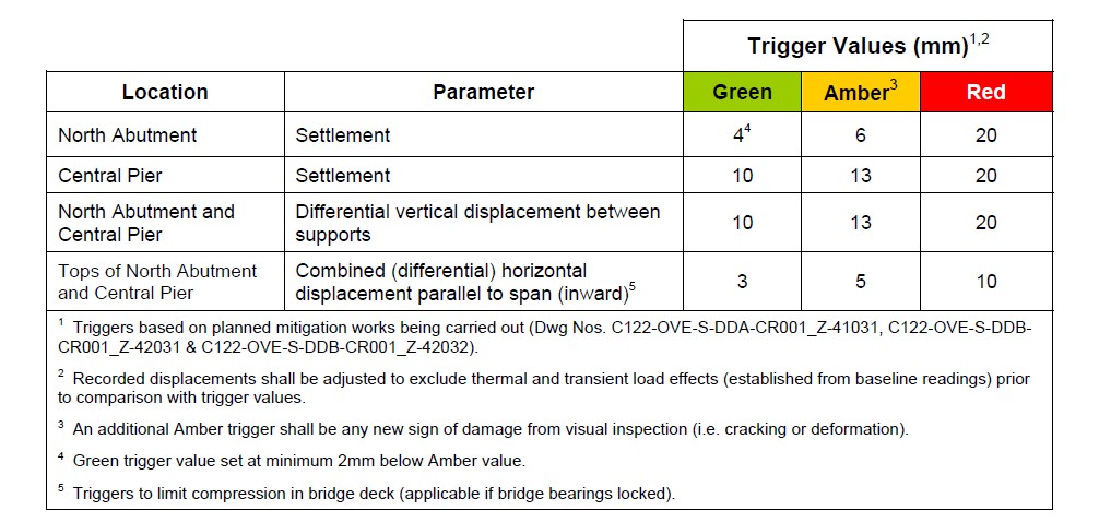
Table 3 – Trigger values prior to works commencement
The most notable values in the table are those for settlement of the North Abutment due to the considerable range between the Amber Trigger and the Red Trigger. The large variation between the two triggers was because the Amber Trigger was set based on anticipated movements, whereas the Red Trigger was based on tolerable movement limits for the bridge.
Further to these trigger values, construction Alert values were set, separated into the mitigation works and the tunnelling works – Table 4. The purpose of these Alert values was to provide control for construction – to provide targets by which each activity should aim to adhere.
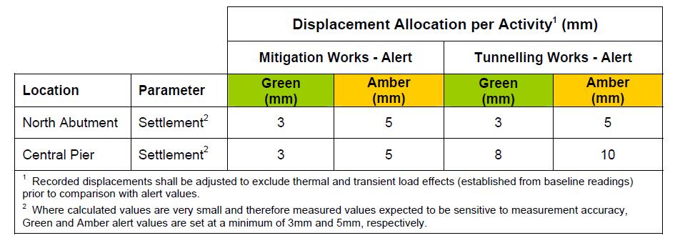
Table 4 – Construction alert values.
Results – Movements Due To Implementation of Mitigation Works
Within two weeks of commencing the piling works, 3mm settlement and 3mm horizontal displacement of the North Abutment had been recorded, thus constituting Green Alerts. It was clear from the early stages that the Amber Trigger for Settlement (6mm) would likely be reached. The initial sequencing, which concentrated on completing the piles closest to the abutment first, was designed to provide an early restraint to ground movements from the construction of subsequent piles. Although the rate of movement did decrease from the initial rate observed, the North Abutment continued to settle gradually whilst piling works continued.
By completion of the vertical piles, the maximum settlement of the North Abutment had reached 5mm, which constituted an Amber Alert for the activity. Considering the high number of piles now installed in front of the structure, it was generally assumed that little or no further horizontal movement would be observed and that this would remain stable at 5mm. This value was of particular importance as the compression of the deck was considered critical for the structural integrity of the bridge. On the other hand, it was expected that the implementation of the 597 raking piles would indeed cause continued vertical displacement of the Abutment.
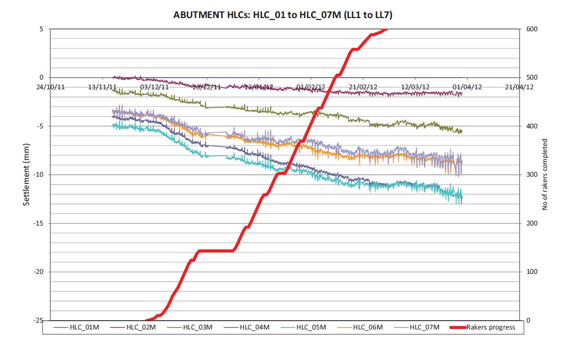
Figure 9 shows the progression of settlement of the North Abutment during the construction of the raking piles. Point HLC_04M and HLC_05M were located closest to the centre of the abutment and show the maximum observed settlement. The graph clearly shows the reaction of the abutment to the piling works and how the rate of piling corresponds to the rate of movement. Indeed, during the Christmas break when no piling works were being carried out, no significant settlement was observed.
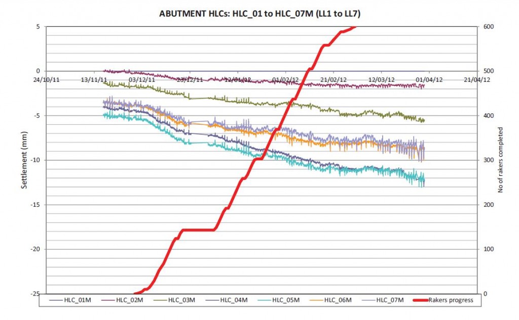
Figure 9 – Chart showing settlement progression during raking pile construction works.
The total movement once all mitigation works were complete is summarised in Table 5. The Amber Triggers reached had required at various times for an emergency Contract Technical Committee (CTC) to be called, during which the Triggers were discussed and actions determined. Typically, the Amber Triggers would then be revised, as was the case for all those below. As a result, prior to the passage of the TBMs beneath the bridge, the Amber Triggers mentioned below were considered to be Green and the value of the Amber Triggers was raised in accordance with the CTC’s decision.
Asset Movement Value (mm) Trigger North Abutment Settlement 12 Amber Horizontal 5 Amber Central Pier Settlement 2 Horizontal 0 Bridge Deck Vertical 9 Compression 5 Amber UKPN Joint Bay Expansion 0 Table 5 – Total movement due to mitigation works.
CONCLUSION
The conclusion to the mitigation works carried out beneath Lord Hill’s Bridge can be best described through the monitoring results following the passage of the two TBMs beneath the bridge. Initial assessments of ground movements caused by tunnel construction estimated that the bridge would settle by approximately 33 mm, causing differential settlements of nearly 28 mm which were considered detrimental to the structure. A further assessment was then carried out assuming the mitigation works described in this report would function as per their design. This assessment concluded that the North Abutment of the bridge should move no more than 6mm in total, including an allowance of 3mm for the construction of the mitigations works. Figure 10 shows the observed vertical movements of the North Abutment from the beginning of Raking pile construction until the end of September 2012, three months after the westbound TBM’s passage through the piled mitigations works and only a couple of weeks since the eastbound TBM’s passage beneath the bridge.
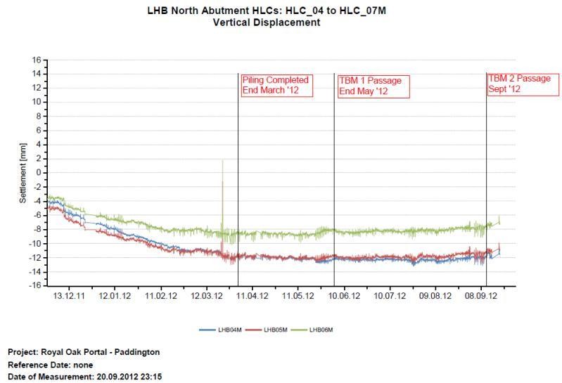
Figure 10 – Graph showing vertical movement, readings start from raking pile construction to TBM transit beneath LHB.
It is clear from the graph that settlement of the abutment ceased shortly after the completion of the mitigation works at the end of March 2012. The Hydrostatic Levelling Cells show that movements continued to be stable during the passage of TBM 1 (end of May 2012) and, more importantly, during the passage of TBM 2 almost directly beneath the North Abutment and through the mass concrete mitigation work.
It was thought initially that the fluctuations observed at the beginning of September (around the 08/09/2012) may be due to vibrations cause by the TBM, however this was more likely due to temperature effects, as this period happened to also be one of the hottest of the year. Furthermore, the apparent heave of the abutment shown on the graph following the passage of the TBM may potentially be due to the TBM tail grouting. However, this is more likely to be settlement of the reference cell, which is located on a retaining wall beyond the Bridge and mitigation works.
In addition to there being no adverse effect to the bridge during construction it is also worth noting that no delays or damage were recorded during the advancement of the TBM through the piled zone – testament to the desired concrete strength values being achieved.
The complete stability of the structure throughout the tunnelling process is testament to the design of the works, as well as to the quality and control of the build. In addition works were completed to programme, causing no delay to the TBM’s.
-
Authors

Aodhán Reaney BSc
M.E Section Engineer, BFK
Thomas Moore HND
Sub Agent, BFK
Brendan Bradley MEng (Hons)
Monitoring Engineer, BFK
Jaime Sevilla BEng
Section Engineer, BFK
Daniel Callaghan BSc (Hons)
Field Engineer, Crossrail