Management of Obstructions and Adverse Ground Conditions During SCL Tunnelling Works at Bond Street and Tottenham Court Road Stations for Crossrail Contract C300/410
Document
type: Technical Paper
Author:
Olivia Perkins MEng(Hons), Vicky Potts MA MSc PhD, Adrian St.John, BEng (Hons) Eur Ing FICE CEng, Shawn Sismondi, BEng (Hons) FGS CGeol
Publication
Date: 31/08/2016
-
Read the full document
Notation
ALARP As Low As Reasonably Practicable
AP1 Access Passage 1 (at Bond Street)
BFK BAM Ferrovial Kier JV, the Main Contractor
BOS Bond Street station
CH2 Concourse Tunnel 2 (at Bond Street)
CH3 Concourse Tunnel 3 (at Tottenham Court Road)
CRL Crossrail Ltd, the Client
DAL Donaldson Associates Ltd, the Contractor’s SCL designer
DDR Due Diligence Review
ETH East Ticket Hall
HAVS Hand Arm Vibration Syndrome
LC London Clay
RESS Required Excavation Support Sheet
RTD River Terrace Deposit
SCL Sprayed Concrete Lining
SRG Shift Review Group
TaM Tube à Manchette for compensation grouting
TBM Tunnel Boring Machine
TCR Tottenham Court Road station
TM Temporary Measure or “toolbox item” such as spiles or pocket excavation which could be deployed in the field to assist excavation stability.
VEW Ventilation Tunnel East (Westbound Running Tunnel) at TCR
VWW Ventilation Tunnel West (Westbound Running Tunnel) at TCR
WTH West Ticket HallIntroduction
An inherent aspect of any tunnelling project is ground risk: how it is identified, quantified and managed throughout the various stages of a project. As far as reasonably practical, early identification of these risks, such as adverse ground conditions or potential obstructions is crucial. If early identification is not possible, having plans and procedures in place for dealing with potential ground risk scenarios as they occur during the construction works is critical to ensure the safety of the workforce.
A number of experiences of potential ground risk were encountered during the sprayed concrete lining (SCL) works on Crossrail contract C300/410 which was constructed by a joint venture of BAM Ferrovial Kier (BFK). The C300/410 works comprised of over 2.5km of SCL tunnels for Bond Street (BOS) and Tottenham Court Road (TCR) Stations and the Fisher Street crossover as well as two 6.2km TBM tunnel drives between Royal Oak and Farringdon. BFK appointed Donaldson Associates (DAL) as their SCL designers for the works. BFK with DAL were responsible for excavation stability up to the point of ring closure.
Despite the majority of SCL tunnelling works at BOS and TCR being through the favourable medium of London clay, there remained areas of local geotechnical challenges. Some of these were expected from the outset, some became apparent as works progressed from records of other nearby excavation works, and some were only encountered during tunnel excavation. Being located in a highly dense urban environment in the centre of London with a long and varied history meant that there always remained a possibility of meeting some form of obstruction from previous structures. However, identification of all potential issues prior to the commencement of the works was challenging and proved to not be entirely possible.
Through a series of case studies, this paper recalls incidents where obstructions or adverse ground conditions arose. These scenarios all had the potential to cause safety risks, impact the tunnel design and/or construction methods and ultimately add time and cost to the works. The paper discusses how these challenges were overcome and examines what could be done in future to further reduce the ground risk through early identification, communication, education and appropriate contingency measures.
Case study #1: Unforeseen Obstructions: Uncharted wells encountered during SCL excavation works for CH2 at BOS and CH3 at TCR
During the excavation of both Central Concourse Tunnel 3 (CH3) at Tottenham Court Road (TCR) and Central Concourse Tunnel 2 (CH2) at Bond Street (BOS), uncharted wells were encountered.
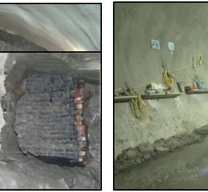
The first of these wells was encountered at TCR; this well was ~300mm outside the excavation profile of CH3. As such, it was not encountered by the excavator, nor visible to the workforce who were unaware of its presence. During the final trimming of the advance the brick lining of the well failed suddenly due to a combination of approximately 10m head of water within the well and the removal of the confining stress of the surrounding clay. This resulted in bricks, clay and water projecting across the face of the excavation. Pictures of the well and worksite at TCR, taken shortly after the failure, are shown in Figure 1.
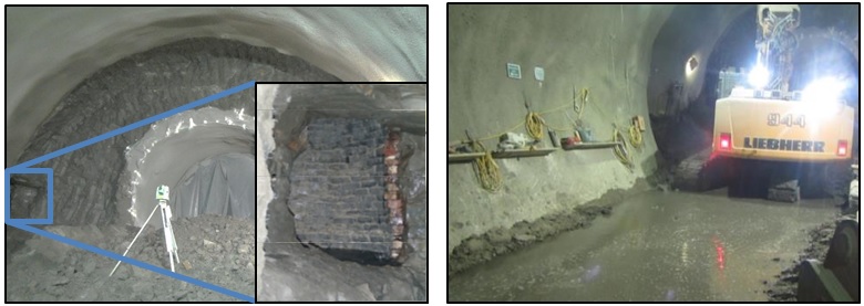
Figure 1 – Uncharted well at TCR (L), water discharged into CH3 tunnel from the well (R) During excavation of CH2 at BOS brickwork was identified within the face. Due to curvature of the brickwork, and the previous experience at TCR, it was immediately assumed to be an uncharted well. A picture of the brickwork exposed is shown in Figure 2.
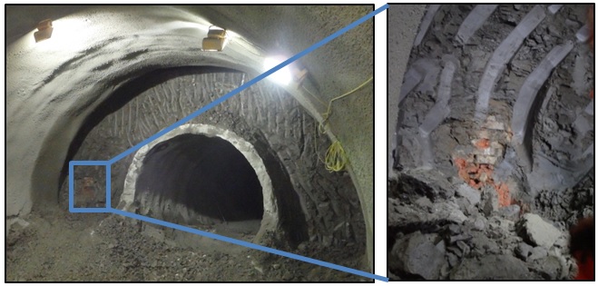
Figure 2 – Uncharted Well at BOS Investigation, Mitigation and Remediation
After the failure of the well at TCR, the initial concern was to ensure stability of the tunnel and safety of the workforce. This was done by sealing the face and implementing an extended exclusion zone. The well was positioned below a grassed area within Soho Square, therefore there were no immediate concerns with regards to stability of structures above the works.
At BOS, the structure did not fail and did not show signs of instability but further investigation was required. Once again, the excavation was stopped and the face was sealed to ensure the safety of the workforce and stability of the tunnel. An additional concern was that the well was located below the party wall between two particularly sensitive structures, which meant the stability of surface structures was of concern as well as tunnel stability.
For both incidents, emergency meetings of all parties were called to decide on the most suitable actions to be taken. In both cases further investigations identified masonry wells approximately 1.4 to 1.6m in diameter. The base of the wells were filled with chalk rubble up to circa 2m below axis level at TCR and circa 4m above axis at BOS.
At TCR, all parties agreed to fill the well opening with shotcrete. Firstly, shotcrete was pumped into the base of the well up to the tunnel axis level; this helped to displace any water in the base. A bleed pipe was then installed to allow any residual water to drain after the remainder of the well opening was filled with shotcrete. Mesh was added to the far and near faces of the primary lining providing additional capacity should any water pressure build up behind the lining. Prior to excavating the corresponding invert advance, targeted depressurisation drillings were undertaken. This allowed for release of any potential water pressure at low level. These probe holes in the invert and additional drillings through the tunnel crown were used to backfill the well with grout as shown in Figure 3.
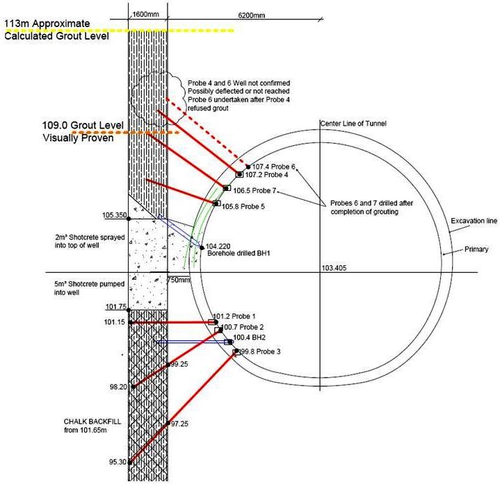
Figure 3 – Cross section of CH3 tunnel and historic well The area around the well was inspected regularly; following the appearance of damp patches on the SCL, further grouting was undertaken. These works could be completed offline without any impact on other tunnelling works. Firstly, a low viscosity fluid resin was used to fill any remaining voids in the ground in the area of the well. Secondly, a hydrophilic grout was injected, forming a barrier between the well and the primary lining. Monitoring was undertaken throughout this grouting period; no deformations were observed which would indicate the development of excessive pressures on the lining.
At BOS as the well had not failed and due to the structures above the tunnel the emphasis was initially on investigation and positively identifying the build and competency. Tunnelling works were put on hold during this time.
The geometry of the well posed particular difficulties. Grouting to a level 3m above the crown of CH2 was required to ensure the structure remained competent during excavation and also to ensure the grout plug did not fall into the tunnel when the lower section of the well was removed. It was geometrically impossible for this to be done from the face of CH2, instead drilling for bleed pipes and verification tubes had to be done from the CH2 pilot tunnel. This placed significant restrictions on the type and size of drilling rig that could be used.
Once the nature of the structure was confirmed, it was agreed that the well was to be grouted. Following completion of the grouting, and testing to confirm its effectiveness, excavation recommenced. Pocket excavation techniques were used through the well, as shown in Figure 4 along with a photograph taken from inside the well. During excavation particular emphasis was placed on monitoring any adverse effects on the structures above the tunnel. Excavation was concluded without further incident.
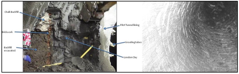
Figure 4 – Pocket excavation of uncharted well (left) and photo of inside of well (right) at BOS Possible Consequences
The position of the well encountered adjacent to CH3 at TCR was in some ways fortunate in that the trajectory of the bricks was directed across the width of the tunnel. Due to the stringent enforcement of SCL exclusion zones, none of the workforce was located near the face and therefore no injuries occurred. Had the well been encountered centrally within the face, the bricks may have been directed down the tunnel with the potential for more serious consequences. Although the well encountered within CH2 was located within the face, fortunately it was dry and therefore remained stable once exposed.
Both events incurred additional cost and time delays to the works. The Tottenham Court Road works incurred remedial works costs to grout up the well. However this work could be done offline after the tunnel drive had passed due to the well’s location outside of the tunnel profile, and therefore incurred only a day’s delay while temporary measures were agreed.
The Bond Street incident incurred investigation and mitigation costs plus additional delay costs; it had a significant impact on the programme adding 25 days. This was due to its location within the tunnel profile, which meant grouting works had to be undertaken before the tunnelling works could continue safely.
Summary: Encountering these uncharted wells caused significant loss to the project both financially and in relation to the programme. It was fortunate that no injuries were sustained by the workforce and highlights the importance of exclusion zones, planned emergency procedures and available contingency measures in such events. Case study #2: Foreseen Obstructions: Under reamed pile / Reinforced Pile BOS
Access passage AP1 connects the new Crossrail station to the existing London Underground station at Bond Street, and runs below Davies Street. The tunnel commenced from the Western Ticket Hall, and was the shallowest tunnel constructed at Bond Street.
During the design process, two piles, which had been used to support a temporary road deck during the 1970’s, were identified which clashed with the tunnel alignment, highlighted in Figure 5(a)(c) below. In addition, a number of other piles were known to be located in close proximity to the tunnel: either redundant piles for the temporary road deck or the piled foundations of an adjacent shopping mall. Although none of these were anticipated to clash with AP1, a risk remained that they might be encountered if for any reason they had not be installed in the anticipated locations. The temporary heading shown in Figure 5(b)(c) was to provide access to a vent duct which also intersected AP1 and was to be backfilled with foam concrete before AP1 could be excavated through it.
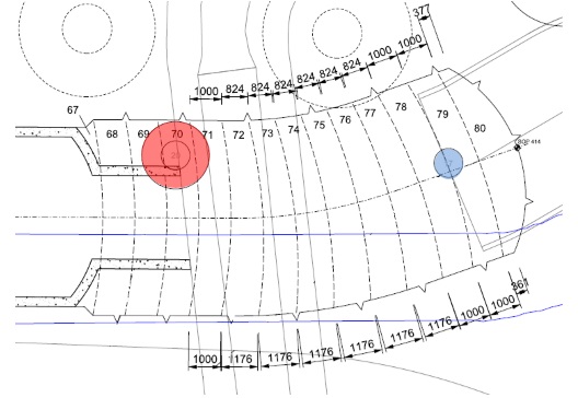
(a) Plan view of AP1 and piles 17 and 21 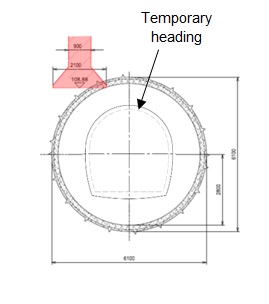
(b) Cross section through AP1 at pile 20 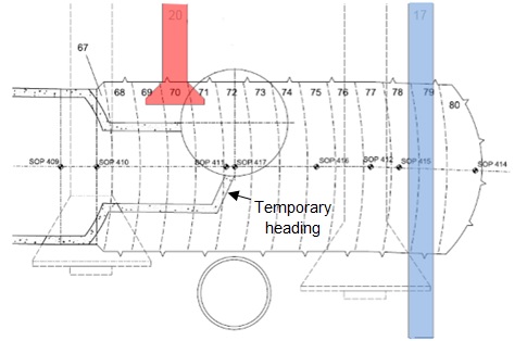
(c) Long section showing AP1 and piles 17 and 21 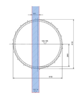
(d) Cross section through AP1 at pile 17 Figure 5 – Location of piles expected to be encountered within the face of AP1
Although no as-built records were available for these piles, detailed design drawings were available. The first pile to be encountered, pile 20, was an underreamed pile, reinforced along its full length. The shaft diameter was 900m, flaring out to 2100m over the lower 865mm of the pile length. The design toe level was 108.88mATD, approximately 420mm below the design excavation level for the crown of AP1. Its location above the shoulder of the tunnel meant that the excavation profile was expected to clip the underreamed base of the pile as shown in the cross section in Figure 5(b).
In contrast pile 17, encountered towards the end of the AP1 excavation, was a 900mm diameter straight shafted pile passing almost through the centre of AP1, with a toe level well below tunnel invert. This pile was reinforced for the majority of the pile length located within the face.
In view of the available information, the design included a detail for connecting the piles to the tunnel lining that would prevent the transfer of any pile loads into the lining. Although these piles were redundant (i.e. not carrying any load) at the time of tunnelling, an assessment of their stability was made prior to the start of tunnelling to assess the risk of them failing and falling into the excavation under their own self-weight. This indicated that there was a reasonable factor of safety against pile slippage, but nonetheless the Activity Plans for this area of work stressed the risk of pile slippage and the importance of exclusion zones being applied for personnel in the tunnel; detailed sequences and possible measures were developed to mitigate the residual risks. A designer-led Toolbox Talk was also given to the miners to raise awareness of the issues associated with tunnelling through and around the piles. One of the miners attending the Toolbox Talk had witnessed the failure of a pile during excavation on a previous tunnelling project; this first-hand experience really highlighted the risks to all of the team.
During excavation only piles 17 and 20 were encountered, as expected. Excavation through both piles progressed safely and with no delays. Figure 6 shows a photograph of pile 20 when exposed during excavation.
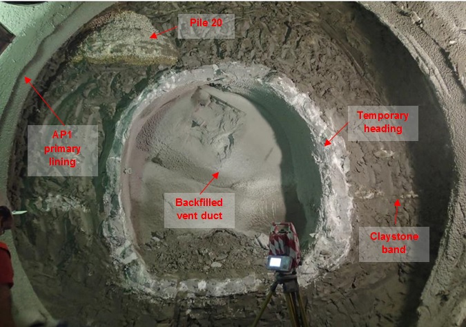
Figure 6 – Pile 20 during excavation of AP1 Summary: Known obstructions provide the opportunity to plan, determine contingencies and give the opportunity to communicate the risk to the rest of the team. The designer led Tool Box Talks on this occasion proved invaluable and should become Best Practice when appropriate. The tool box talk promoted discussion, providing site operatives the opportunity to ask direct questions and gain clear knowledge and understanding of key risks and why certain methods of work have been chosen. Case study #3: Foreseen Obstruction: Steel pile casing obstruction at Bond Street ETH
Through undertaking a review of as-built information around Bond Street station, a temporary steel pile casing was identified that had been left in the ground by a previous project. This would cause an obstruction to the TBM drive and therefore needed to be removed prior to the TBM’s arrival in this area.
Removal of the pile casing from the surface was not practicable due to the presence of significant obstacles, but the casing was sufficiently close to the temporary shaft at BOS ETH to enable removal of the casing via open face SCL tunnelling (see Figure 7).
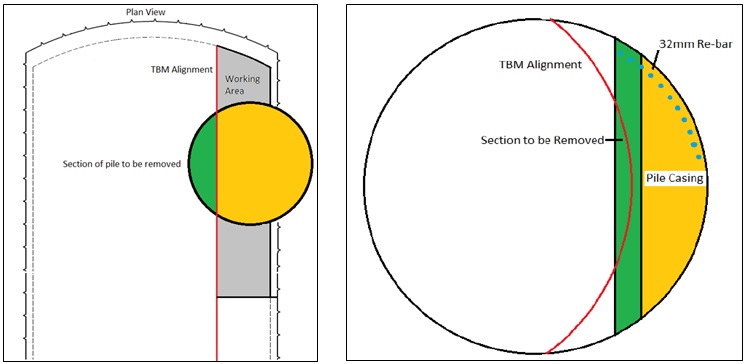
Figure 7 – Plan view of SCL tunnel and pile casing (L), pile casing relation to TBM alignment (R) A short temporary SCL heading was designed and constructed, which provided BFK with access to intersect the pile casing. Once sufficiently exposed, a series of probes and lances were drilled and connected to the casing; excess water was removed and a series of steel bars were then inserted through the casing to “choke” any potentially unstable material. Grout was injected through a number of locations to stabilise the material within the pile casing. The steel casing was then carefully cut away in sections using oxyacetylene torches, and shotcrete was immediately applied in stages once each section of the obstruction had been removed as per Figure 8. The heading was then backfilled with low strength foam concrete prior to safe passage of the TBM.
The SCL tunnel works to remove the steel pile casing incurred significant additional cost, although this was far less than what would have been incurred if this obstruction had not been identified and removed from the path of the TBM.
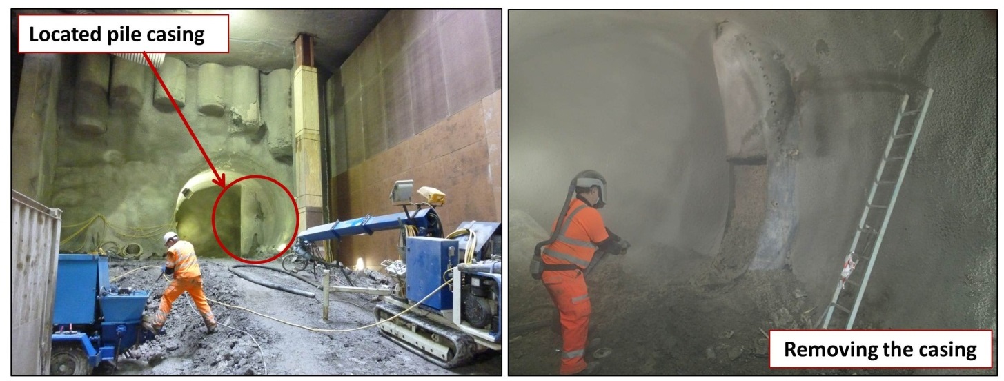
Figure 8 – SCL heading to locate the casing (L) and process of removal (R) Summary: Co-ordination and review of relevant information and recognition of the implications is essential. Identification of an obstruction, even at short notice, enabled measures to be taken to remove the obstruction, incurring a minimal delay to the TBM and ultimately the project. Case study #4: Adverse Ground Conditions: Permeation grouting over VWW, Tottenham Court Road
TCR station includes two ventilation tunnels, at a shallower elevation than other station tunnels at TCR. As such, they presented the project team with a high level of geotechnical risk, due to the relatively close proximity of the water-bearing River Terrace Deposits (RTD) overlying the London Clay above the tunnel crown. Figure 9 shows the location of the western ventilation tunnel, VWW, in plan.
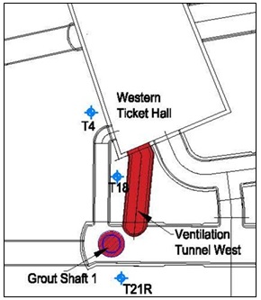
Figure 9 – Plan View of VWW with location of nearest Boreholes The geological long section for VWW was initially based on data from nearby boreholes. However, BFK were in a fortunate position to have been responsible for the excavation of the adjacent TCR Western Ticket Hall[1]. This provided BFK with easy access to geotechnical records from the dig, and afforded designers from DAL the opportunity to visit the excavation to undertake sampling, photographs and additional logging as necessary.
As a result of updating BFK’s ground model with information from the diaphragm wall panel construction records and the excavation records for the box, a very localised dip in the surface of the London Clay was identified immediately above the crown of VWW, as per Figure 10, that had not been evident from the available borehole logs. In the worst case, this suggested only 1.2m of clay cover above the tunnel excavation, of which perhaps 500mm might be highly weathered and fissured. The RTD above the London Clay are saturated and form a substantial aquifer; although unlikely, the consequences of breaching this clay horizon during open face SCL tunnelling could have been potentially very serious.
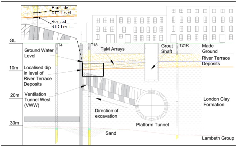
Figure 10 – VWW Geological Section The buildings directly above tunnel VWW had been predicted to have been exposed to an “acceptable” level of settlement; however, this assessment had been based on an assumed volume loss which, if the clay horizon were breached, would no longer be applicable.
This situation therefore presented an unacceptably high risk to the project team, in terms of safety of the tunnel and workforce, and in terms of asset protection. As a result, a number of potential solutions were explored and evaluated:
Potential Solutions Comments 1. Ground freezing X Impractical due to lack of access. 2. Install pipe arch from WTH X By this stage, BFK no longer had access to the WTH box.
X Even if access were possible, this would have entailed extensive working at height for personnel and heavy plant (circa 8m above pit bottom) for several weeks.
3. Pilot tunnel within VWW followed by in-tunnel ground treatment from pilot üPilot tunnel position flexible within profile of the VWW profile.
X This option entailed severely limited working space restrictions for drill rigs.
X The site team had a low degree of confidence that this could be achieved safely, since it required overhead ground treatment (drilling and grouting) directly above a small, inclined, tunnel.
X In-tunnel ground treatment involved drilling into water-bearing gravels with associated risks
X An arrangement with the pilot tunnel in crown would still have entailed the workforce undertaking open face SCL tunnelling in the area of highest risk and lowest clay cover.
4. Timber heading followed by in-situ concrete lining ü This solution mitigated the risk of disturbing clay and provided shorter advance lengths.
X Hand mining introduced new risks (HAVS, manual handling) and would require a change of tunnelling method and therefore a wholesale re-design (and Cat III check) of the permanent works.
X It also did not address the risk presented by the perched water table.
5. In-tunnel spiling and/or ground treatment (from a temporary headwall) X Although this had the potential to stabilise the ground above the crown, this solution did not address the risk of water ingress.
X The spile installation activity could disturb the ground and propagate failure by perforating the clay. This was of particular concern since these works would be carried out “overhead” from within the tunnel.
6. Permanent works realignment to minimise tunnel length and inclination angle ü The VWW tunnel was constrained by the entry point into the TCR WTH box, and the connection to the platform tunnel, but a small realignment was possible and would minimise the amount of excavation required at the shallowest elevation.
ü This had no impact upon the functionality of the permanent works, it was simple and quick to implement, and significantly reduced the residual geotechnical risks.
7. Permeation grouting of RTD from nearby grout shaft #1 ü This would effectively mitigate the risk at source, stabilising the ground and pushing water away from the most vulnerable area, and it could be carried out off-line without disrupting the SCL mining cycle.
ü It reduced the likely volume loss and ground movements, thus reducing the risk to both the workforce and the surrounding assets.
After careful consideration, options 6 and 7 were implemented. These were augmented by further in-tunnel “temporary measures” which could be deployed if necessary. This included pocket excavation, reduced excavation advances and increased temporary shotcrete thicknesses.
The permeation grouting was carried out on behalf of BFK by Keller BAM Ritchies from grout shaft #1, using TaM pipes to deliver the grout to the required zone. A phased sequence of grouting works was designed by DAL using primary, secondary and tertiary passes of sodium silicate grout injections, with stop criteria based on both volume and pressure restrictions. The success of the grouting was validated using probe holes, endoscopic cameras and falling/static head tests. Once these were satisfactorily completed, the excavation of VWW was allowed to commence.
Again, additional cost was incurred for the works to stabilise the ground around VWW however there were minimal delays to the programme as they were completed offline. In the end, limited pocket excavations were also successfully deployed as a further precaution in the most vulnerable positions, and the tunnel was completed rapidly, safely and with minimal ground movement.
Summary: Continuous review of emerging data and recognition of relevant/critical information allows foresight and identification of potential risks. It is important to have competent/ experienced personnel these records to ensure the implications are understood and clearly communicated to the project team. Case study #5: Good Practice: Tube-a-Manchettes
The tunnelling works at both sites were supported by compensation grouting to limit surface settlement; a process of injecting soft cementitious grout at high pressure into the ground through tube-a-manchettes (TaMs), installed within the London Clay above the station tunnels. The TaMs were made from 63mm dia. steel tubes with rubber sleeves covering the grout release holes.
Due to the required level of the TAM’s to cater for the majority of the tunnels at TCR, and the relatively shallow levels of both ventilation tunnels VEW and VWW, it was identified that some of the TAMs would be encountered during the excavation of the ventilation tunnels. This led to concerns regarding lining integrity and safety of the workforce when removing the TAM pipes. The permanent works designer would not permit the steel pipes to be left within the lining.
The location of the TaMs, determined by Maxibore 3D surveying, allowed their expected position within the face of the tunnel excavation to be plotted on the predictive ground models compiled by the BFK geotechnical engineering team for each tunnel. An example, for VEW, is shown in Figure 11. This early identification provided the construction team with time to discuss and plan a method for dealing with the TaM pipes.
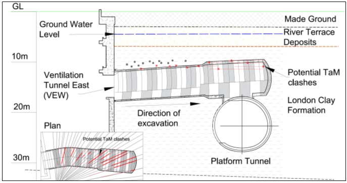
Figure 11 – Predictive ground model for VEW demonstrating clashes with TAM pipes An Activity Plan was written to clearly outline the process of either leaving in place or removing the TaM pipe depending on its position relative to the primary lining profile. Clear communication between the on-site geotechnical and site engineers was crucial in agreeing the way forward. Images of the exposed TaM pipes can be seen in Figure 12. All TaMs were identified and removed or sprayed in successfully with no noticeable impact on time in the excavation cycle of the VEW and VWW tunnel construction, and no cost impact.
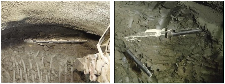
Figure 12 – TAM pipes exposed during excavation of the VEW tunnel Summary: Again, early identification of obstructions allowed opportunity to plan a safe method of work and have contingency plans to deal with obstructions causing minimal impact on the cycle of tunnelling activities. Discussion
Unforeseen obstructions can have a very significant impact on the safety, programme and cost. The safety risks associated with unforeseen obstructions are exemplified by the well encountered at TCR; if the well position had been more central, the bricks would have propelled along the tunnel. Had an exclusion zone not been in place, then the potential outcome could have been much more serious.
This highlights the importance of a strategy for managing the risks associated with obstructions. A comprehensive desk study to understand the history of the site is paramount, and the findings should be used to inform the scope of a geotechnical site investigation. The more thorough these are, the better the chance of identifying obstructions in advance of tunnelling, allowing appropriate mitigation measures to be adopted and minimising the impact on cost and programme.
Nonetheless it is not always possible to identify all obstructions at this stage, for example the wells. Due to the long history of development in central London, there were not always records of specific wells and their locations. Neither of the wells encountered during C300/C410 were accessible from the current ground surface, as they were buried below newer infrastructure and therefore they were highly unlikely to have been identified during site investigation. It must be remembered that boreholes provide limited data at a discrete number of locations, and can miss very localised features such as obstructions, or indeed variations in ground conditions, such as the local dip in the surface of the London Clay above VWW at TCR.
Probing from the tunnels to evaluate ground conditions ahead of the excavation face[2] may detect obstructions, but based on typical patterns (extending ~1m beyond the tunnel profile) and spacing (probing arrays typically every 6-10m of tunnelling) coverage is still limited. Figure 13(a) illustrates that it is unlikely that probing would have encountered the well just outside CH3 at TCR. Although it may have encountered the well in CH2 at BOS, detection is by no means guaranteed. During investigation works at BOS, the well location was only positively identified using endoscopic cameras in the probe holes. During drilling itself no change in resistance had been observed.
The installation of the TaMs for compensation grouting at BOS and TCR, is considered to have been the best opportunity to identify the wells; the process of installing the TaMs provided extensive probing coverage (typically 1-2m spacing) in the London clay above the tunnels. Figure 13(b) illustrates this in relation to the well in CH2 at BOS. Yet these still only provide a discrete record and in this case neither well was detected.
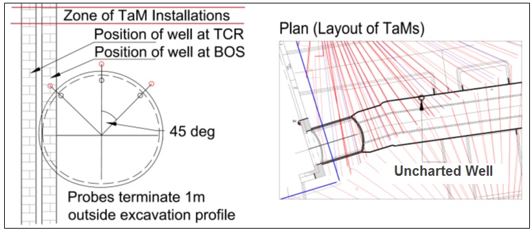
Figure 13 – (a) Typical Probing Arrangement (left), (b) Position of TaMs (right) After encountering the well at TCR, enquiries were made into the feasibility of using geophysics within the mining cycle. Unfortunately the constraints of the tunnel mining cycle and the composition of the tunnelling lining and London Clay meant that the various methods considered were deemed unfeasible. However, with ever evolving technology, this may be a development area for the future.
The process for the management of obstructions on C300/C410 is illustrated in Figure 14. This continuous cycle of as-built information fed back into the geological model as works progressed proved to be a very effective method of identifying risks before they were encountered in the tunnel face.
It was in this way that the localised reduction in clay cover above VWW at TCR, the TaMs in the face of VEW at TCR, and the pile casing at BOS were identified. The 3D ground model owned and updated by BFK was critical to this process, providing a central and consistent format for incoming data, which were subject to continuous review. It was vital that new information was reviewed by the design team as well as the construction team to ensure that the implications were fully understood, and where risks were identified they were then communicated effectively, allowing appropriate solutions to be developed ahead of tunnel excavation by the wider team working in close collaboration.
![Figure 14 - Risk Management for obstructions [2]](https://learninglegacy.crossrail.co.uk/wp-content/uploads/2016/12/7E028-Figure-14.jpg)
Figure 14 – Risk Management for obstructions [2] The value of a comprehensive desk study is evident from the experience with the piles in AP1 at BOS, however the experience obtained on C300/C410 illustrates that even with comprehensive desk studies and site investigation, it is not always possible to identify all obstructions. Through the desk study, site investigation and review of incoming site records, it is considered that the construction risks were reduced to ALARP for C300/C410. Nonetheless it must be recognised that this does not mean zero risk, as it is neither feasible nor practicable to plan for all eventualities.
Clearly measures should be taken to protect the safety of the workforce at all times, but these need to be proportionate to the level of risk. In the case of SCL tunnelling, it is considered that this is best achieved by application of exclusion zones and maximising the use of mechanical excavation. Significant advances have been made on Crossrail to improve the safety of SCL works through effectively implementing and managing exclusion zones to minimise the number of people close to the face at any time[4]. Where man access to the excavation face is unavoidable the workforce should be protected, for example the excavator cab should be reinforced, and overhead canopies or Falling Object Protection Systems (FOPS) should be used when possible. Further developments in remote surveying technology and automated tunnelling plant may have a considerable beneficial impact although this may come at the cost of reduced flexibility in the tunnel design. As a last line of defence, a supply of batched shotcrete was always available at the face during excavation as a standby to seal the face and halt the works in case of problems.
Conclusions
The case studies described in this paper cover a range of scenarios relating to obstructions and difficult ground conditions, both foreseen and unforeseen.
Where the obstructions were foreseen either from the very start (e.g. the piles in the face of AP1) or discovered as works progressed from developing a better understanding of ground conditions (e.g. low clay cover in VWW, TaMs in VEW), the design and construction teams were able to develop appropriate solutions in advance of tunnelling at the affected locations, and Toolbox Talks were arranged to brief the miners. This minimised the risks to the workforce and the impact on cost and programme, and highlights the importance of comprehensive desk studies, and also of continuous review of geotechnical and excavation records by the geotechnical engineers and design team as they become available as works progress.
Nonetheless there remains a chance that not all obstructions will be detected by a desk study, for example the two uncharted wells. These were also not detected during the installation of the TaMs used for compensation grouting above the tunnels, and are unlikely to have been detected by intermittent probing ahead either. In such cases the safety of the workforce is best protected using exclusion zones, providing protection to those workers closest to the face (e.g. the Falling Object Protection Structure (FOPS) used to protect excavator cabs) and maximising the use of mechanised excavation.
By sharing these incidents, and the lessons learnt, it is hoped that further progress can be made in reducing ground risk in tunnelling works, in relation to both health and safety, and cost and programme implications.
References
[1] Yeow, Nicholson, Man, Ringer, Glass, Black, 2014. ‘Application of observational method at Crossrail Tottenham Court Road station’ Proceedings of the ICE – Geotechnical Engineering. 167(2):182-193
[2]Gakis, Salak, St.John, 2015. ‘Innovative geotechnical risk management for SCL tunnels’, Proceedings of the ICE – Geotechnical Engineering. 168(5):385-395
[3] BS6164:2011 ‘Code of practice for safety in tunnelling in the construction industry’ British Standards Institution
[4] Best Practice Guide – SCL Exclusion zone Management, Available through the British Tunnelling Society (https://www.britishtunnelling.org.uk)
-
Authors

Olivia Perkins MEng(Hons) - BAM Ferrovial Kier
BAM Ferrovial Kier JV
Vicky Potts MA MSc PhD - Donaldson Associates Ltd
Donaldson Associates Ltd

Adrian St.John, BEng (Hons) Eur Ing FICE CEng - BAM Ferrovial Kier
Adrian St.John is a Fellow of the Institution of Civil Engineers and a Supervising Civil Engineer. He has spent most of his 24 year career working on major infrastructure and tunnelling projects in the UK and overseas, including the Brighton Stormwater tunnel and High Speed 1 at St Pancras. He spent 6 years as Chief Engineer for BFK Joint Venture who were the main contractor on Crossrail contracts C300, C410 and C435, and is the Design Director for Carillion Eiffage Kier (CEK) Joint Venture bidding for the forthcoming HS2 main civil works.