Multi-aquifer pressure relief in east London
Document
type: Technical Paper
Author:
T.O.L Roberts, E. Linde, C. Vicente, G. Holmes, ICE Publishing
Publication
Date: 07/09/2015
-
Read the full document
1 Introduction
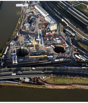
Crossrail is a major new east-west rail link through central London. The twin 6.2m diameter running tunnels under central London were driven by TBMs from the west and east to meet at Farringdon. This paper is concerned with the dewatering and pressure relief measures required for the eastern drive and auxiliary shafts located at Limmo peninsula between the Isle of Dogs and the Royal Docks, Figure 1. The site is bounded by the tidal waters of Bow Creek to the west, Canning Town Station to the east (Jubilee Line and Docklands Light Railway) and by the Lower Lea Crossing (road bridge) to the south. The location was chosen to facilitate material delivery and muck-away for the TBM drives by river.
The main shaft at Limmo is 30m i.d. formed by a circular, 1.2 m thick, diaphragm wall. Ground level at the shaft site is at 107mTD (0.00mOD = 100m Tunnel Datum). The shaft dig depth was 44.3m and the toe depth of the diaphragm walls was to 55m below ground level (bgl). The shaft includes a 500mm thick ‘no fines’ concrete drainage layer below the base slab. This layer is pumped by sumps during the 3 year tunnel construction period to avoid build-up of pressure below the base slab. Once the TBM drives are complete this main shaft will be fitted out to provide ventilation and pedestrian access to rail level.
The finished shaft will have sufficient structural integrity and dead weight to resist groundwater uplift pressures. In order to facilitate access to launch and service the TBMs for the main 8.3km drives to Farringdon and secondary 0.9km drives to the Victoria Dock portal a second auxiliary shaft was required. The auxiliary shaft is 27m i.d. formed by sheetpiles through the overburden with Sprayed Concrete Lining (SCL) below. Dig depth for the shaft was 39.8mbgl and it was completed with a domed base to resist uplift groundwater pressures during the period of the TBM tunnelling works. On completion of tunnelling the auxiliary shaft will be backfilled. The layout of the shafts is shown in Figure 2.
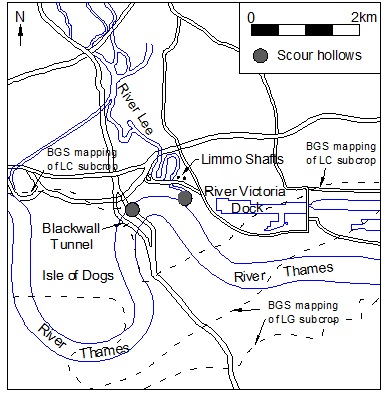
Figure 1 – Site Location in east London
The main and auxiliary shafts were connected by twin SCL tunnels plus back and fore shunts at rail level at approximately 68 mTD (39 m depth).
1.1 Borehole data
A large number of boreholes were drilled at the site to investigate the ground profile and these have been summarised in the schematic ground profile in Figure 3. This shows the typical geological sequence present across central London comprising recent superficial deposits of Made Ground, Alluvium and Terrace Gravels underlain by London Clay, the Lower London Tertiaries with chalk below. Variations in the strata interface levels suggest evidence of faulting in the vicinity, mainly to the west of the shafts.
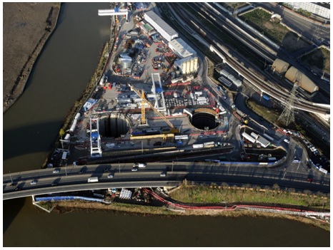
Figure 2 – Aerial photograph of site from the south
1.2 Hydrogeology
The Terrace Gravels are water bearing, forming a discreet Upper Aquifer. The London Clay provides a confining layer for the regionally important Lower Aquifer comprising the chalk and Thanet Sand[1]. The granular horizons in the lower Lambeth Group are also in good hydraulic connection with the Lower Aquifer system. The granular horizons in the upper Lambeth Group above the Mid-Lambeth Hiatus (MLH), and in the Harwich Formation, have limited hydraulic connection to the Lower Aquifer and are sometimes referred to as the Intermediate Aquifer. The granular horizons in the Lambeth Group are known to be laterally intermittent[2]. Water levels in the Upper Aquifer are approximately 100mTD and are controlled by levels in the adjacent river which is tidal.
Recharge to the Lower Aquifer is via the chalk outcrops to the North and South of London and also directly from the Terrace Gravels/Thames where the London Clay and Lambeth Group subcrop 2 to 3km to the south of the site. Known scour hollows in the surface of the London Clay are shown on Figure 1. The scour feature at the Blackwall Tunnel is known to penetrate to the Lambeth Group whereas the one at the mouth of the River Lea is thought not to penetrate through the London Clay. Excessive abstraction for water supply in central London led to a substantial lowering of the natural groundwater level in the Lower Aquifer between about 1850 and 1965. Prior to 1850 groundwater levels at Limmo were thought to be up to 110mTD[3],[4], falling to about 85mTD by 1965 and recovering to the levels shown in Figures 3 and 4 by the start of the works. The profiles in Figure 4 have been interpreted from monitoring data obtained from the pumping test data and from experience from the Crossrail data base.
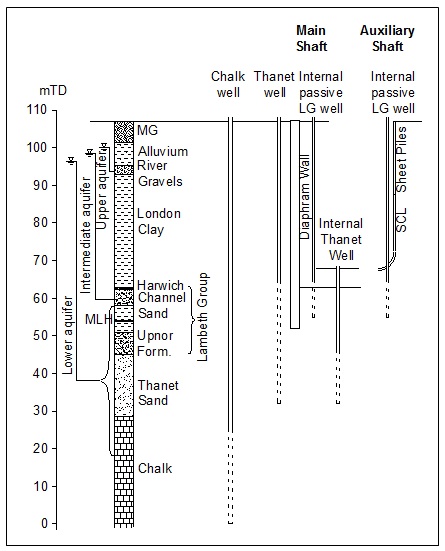
Figure 3 – Schematic section showing ground profile.
1.3 Pumping test
A comprehensive programme of pumping tests was commissioned prior to the works. This involved the installation and test pumping of wells individually targeting the chalk, Thanet Sand, Lambeth Group granular horizons (two wells) and Harwich Formation (two wells). The test regime is summarised in Table 1 and the distance drawdown data is summarised in Figure 5. The following should be noted with respect to Figure 5.
- A vacuum was applied to the Harwich Formation and Lambeth Group wells in order to maximise drawdown.
- Data for the first Harwich test well is not included as there was no discernible response in any of the piezometers.
- The Lambeth Group wells targeted the Lambeth Group above the MLH. The data for the two Lambeth Group wells has been combined and normalised to an average flow of 0.45l/s.
- Piezometers which showed no response are not included.
- For the Harwich Formation tests, Lambeth Group piezometers above the MLH which responded to pumping are included, and vice versa for the Lambeth Group tests.
- The Thanet Sand test data includes piezometers in the Upnor Formation (generally granular horizon of the lower Lambeth Group, usually with good hydraulic connection to the Thanet Sand).
- The Chalk test includes piezometers in the Thanet Sand and Upnor Formation.
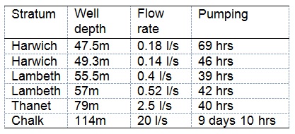
Table 1 – Pumping test regime.
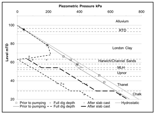
Figure 4 – Summary of pore pressure profile
Figure 5 shows the generally good response to pumping of all principal horizons. The successive order of magnitude increase in flow from the Harwich/Lambeth to Thanet and again from the Thanet to Chalk is evident. Also evident are the more variable localised response of the Harwich/Lambeth above the MLH and the relatively localised response of the Thanet wells compared to the more extensive response for the chalk pumping.
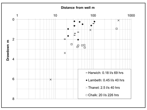
Figure 5 – Summary of pumping test data.
2 Depressurisation Requirements
Groundwater in the Upper Aquifer is cut-off by the diaphragm wall and sheet piles around the main and auxiliary shafts respectively.
During construction of the main shaft there was a concern that high groundwater pressures in more permeable layers trapped under less permeable layers would cause uplift failure of the soils in the base of shaft. This could occur at the base of the London Clay and at the various granular horizons in the Lambeth Group down to the Upnor Formation.
The design requirement was to reduce the groundwater pressure in these strata such that the design groundwater pressure multiplied by 1.1 is less than the overburden pressure multiplied by a partial factor of 0.9, BS EN 1997-1:2004 2.4.7.4. In other words the groundwater pressure needs to be reduced to less than 0.82 times (0.9/1.1) the over burden pressure at every level below the base.
3 Target Piezometric Levels
The target piezometric level can be calculated for any horizon and depth of excavation by taking the strata interface levels as indicated in Figure 3 and assuming a density for all of the soils present of 20kN/m3. Results for the main shaft are given in Table 2.
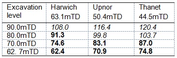
Table 2 – Target groundwater levels at selected horizons for main shaft. Values in italics are above and values in bold are below pre-construction groundwater levels.
For the main shaft, due to the uncertainties regarding diaphragm wall-soil interface shear strength, it was difficult to take account of soil shear strength and wall friction in a defensible manner. This was much easier to justify for the smaller auxiliary shaft constructed by SCL methods with a domed base. A calculation for the auxiliary shaft was carried out taking soil shear strength into account and this indicated minimal requirement for pressure relief in the Upnor Formation and below, and a reduction to 81.5mTD in the Harwich Formation. Once complete, the SCL lining for the auxiliary shaft was designed so that no pressure relief was required for the 3 year tunnel construction period.
Once the main shaft base was installed this was keyed into the diaphragm walls to mobilise the base slab and shaft weight to resist uplift pressures. Taking all of the installed concrete into account resulted in a target piezometric pressure for the 3 year tunnel construction period of 93.5mTD, amounting to only a few metres of drawdown.
4 Depressurisation Strategy
The requirement for substantial pressure reduction in the Upnor Formation for the main shaft construction necessitated pressure reduction in the Thanet Sand and chalk. Although the chalk and Thanet are in good hydraulic connection the results from the pumping test indicated that appreciable local drawdown in the Thanet could be achieved without a corresponding reduction in the chalk. In order to minimise both abstraction flows and extent of drawdown the chalk dewatering was only intended to achieve part of the required drawdown in the Upnor Formation with the remainder achieved by local Thanet wells.
The pumping test showed that the Lower Aquifer pumping had minimal impact on pore pressures in the Lambeth Group above the Mid-Lambeth Hiatus. For the main shaft the granular horizons above the Mid-Lambeth Hiatus are cut-off by the diaphragm wall such that only a minimal passive relief well system was needed.
Some drawdown was required in the Upnor Formation after the base slab was cast and it was considered that this could be achieved with internal Thanet passive relief wells.
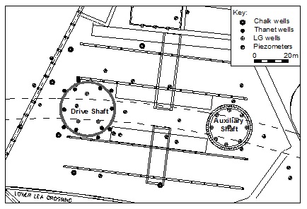
Figure 6 – Site layout showing shafts, wells and piezometers.
The auxiliary shaft is founded towards the base of the London Clay. The wide impact of the chalk dewatering for the main shaft provided the lower aquifer pressure relief required for the auxiliary shaft during shaft construction. Internal passive wells provided the pressure relief required in the Harwich Formation and Lambeth Group channel sands. This needed to be a more extensive system than for the main shaft because the SCL method of construction provides no cut-off below dig level.
A key benefit of this strategy was that it avoided the need for continuous pumping from the chalk throughout the 3 year tunnel construction program. The strategy exploits the minimal hydraulic connection between the intermediate aquifer and the lower aquifer and the restricted hydraulic connection between the Thanet Sand and chalk which have caused difficulty on previous construction projects in a similar geological setting[5]. The proposed well array is shown in Figure 6 and summarised in Table 3.
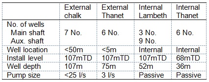 Table 3 – Summary of dewatering well array.
Installation of the internal Lambeth Group passive wells from ground level allowed a program of test pumping prior to excavation. For the main shaft this demonstrated the effectiveness of the well array and the integrity of the diaphragm wall cut-off below dig level.
5 Monitoring Results
Manual and data logger monitoring, using vibrating wire transducers, was undertaken on the piezometer array indicated in Figure 6. The piezometer array included instruments with response zones in all strata present. A sample of the data collected is presented in Figure 7. Pumping started with three of the chalk wells in December 2011. These were switched off, and subsequently restarted in February 2012 with pumping on the external Thanet wells commencing mid-March 2012.
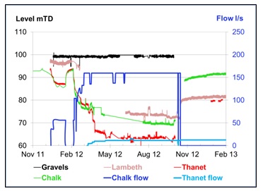
Figure 7 – Sample of monitoring data in vicinity of main shaft.
It can be seen that the Thanet Sand and chalk initially responded together, with an additional 8 m of drawdown generated in the Thanet Sand when the Thanet well pumping commenced. Abstraction flows from the chalk were 160 l/s with flow from the external Thanet Sand wells at 11 l/s. Data for the Lambeth Group is intermittent. The Lambeth Group showed minimal response to the Chalk pumping. The Thanet wells are screened up into the Lambeth Group which did respond when pumping started on the Thanet wells. Note that the data plotted in Figure 7 is for instruments installed around the outside of the shafts. Figure 4 shows pore pressure data points prior to construction, when the main shaft reached full excavation level and when the external chalk and Thanet wells were shut down so that only the passive internal Lambeth and Thanet wells were operational (which was the case during the 3 year tunnel construction period). The lines show the interpreted pore pressure profile within the main shaft at the same program points in the course of construction.
Level monitoring indicated that there was no discernible settlement (i.e. <2mm) when pumping commenced from the chalk wells only. Some settlement became evident local to the shafts when pumping commenced from the Thanet Sand and the auxiliary shaft passive relief wells. This suggests that the settlement in this vicinity was primarily related to the depressurisation of the upper Lambeth Group. Surface settlements of the order of 20 mm were recorded 50 m from the shafts by the end of the 8 month shaft construction period with no measurable settlement 400 m from the shaft.
6 Conclusions
A comparison between the estimated abstraction flow based on simple linear superposition of the pumping test data and the measured flows is given in Table 4. The high actual abstraction flow for the Thanet wells relative to the estimated flow is due to the recharge from the chalk below. The rate of recharge would be expected to be disproportionally higher as greater drawdown (compared to the pumping test) is achieved in the Thanet Sand relative to the chalk which is in very close proximity below.
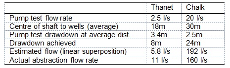
Table 4 – Comparison between estimated and actual flows
The situation for the chalk is reversed with flows less than suggested by linear superposition. This is because the limited recharge to the chalk results in an increasing distance of influence and corresponding reduction in flow over time. An analysis based on the initial 20 m of drawdown achieved gives a very close match between the estimated and measured flows.
References
[1] Royse, K.R. de Freitas, M. Burgess, W.G. Cosgrove, J. Ghali, R. C. Gibbard, P. King, C. Lawrence, U. Mortimore, R. N. Owen, H. & Skipper, J. 2012. Geology of London, UK, Proceedings of the Geologists’ Association 123, 22–45.
[2] Page, D. & Skipper, J.A. 2000. Lithological characteristics of the Lambeth Group, Ground Engineering 33: 2.
[3] Environment Agency. 2014. Management of the London Basin Chalk Aquifer: Status Report, Environment Agency, London.
[4] Simpson, M.A. Blower, T. Craig, R. N. & Wilkinson, W.B. 1989. The engineering implications of rising groundwater levels in the deep aquifer beneath London, SP69, CIRIA, London.
[5] Linney, L.F. & Withers, A.D. 1998. Dewatering the Thanet Beds in SE London: Three case histories, Quarterly Journal of Engineering Geology 31, 115–122.
-
Authors

T.O.L Roberts
WJ Groundwater Ltd
E. Linde
OTB Engineering
C. Vicente
Dragados Sisk JV
G. Holmes
WJ Groundwater Ltd
