Overcoming inclusions within Diaphragm Walls at Cambridge Heath Shaft Whitechapel
Document
type: Technical Paper
Author:
Pierre D’Alessio, Andrew Taylor, ICE Publishing
Publication
Date: 31/08/2016
-
Read the full document
Notation
C140 – Crossrail Contract, Hyder Consulting
C511 – Crossrail Contract, Bam Nutall Kier JV – Diaphragm Wall Construction
C512 – Crossrail Contract, Balfour Beatty, Morgan Sindall, Vinci JV – Main Construction
C510 – Crossrail Contract, Balfour Beatty, Morgan Sindall,Vinci JV – SCL Platform Tunnels
CHS – Cambridge Heath Shaft, Whitechapel
LUCT – London Underground Crossrail Team
FE – Crossrail Field Engineer
JV – Joint Venture
SCL – Sprayed Concrete Lined Tunnels
CTC – Contract Technical CommitteeIntroduction
The new Whitechapel Crossrail station is one of six major new Crossrail underground stations in Central London that will additionally provide an interchange between the Hammersmith and City, District and Overground lines.
The station with platforms 250 m long is being constructed in tunnels approximately 30 m below ground level. Two major access shafts have therefore been constructed, one at each end of the station. Cambridge Heath Shaft (CHS) is positioned at the east end of the station and provides tunnel ventilation via two very large emergency fans and draft relief ventilation for normal running of the railway and emergency escape and intervention for rail users. The construction of the Cambridge Heath Shaft was split between C511 (Diaphragm Walls & Capping Beam) and C512 (excavation & shaft internals and head house). The paper also highlights the interfaces between the two contractors that were key to successful repair of the defects.
Cambridge Heath Shaft
Cambridge Heath Shaft sits between the two running lines and interfaces with them via three short adit tunnels two of which are for ventilation and lead directly to the platform tunnels and the third larger adit leads off a cross passage and gives access to the emergency access stairs.
The shaft is facetted, nominally circular, on plan 28 m internal diameter and extends to a depth of approximately 30 m below ground level. It is constructed from deep Diaphragm Walls with a substantial Reinforced Concrete (RC) capping beam. The interior of the shaft is formed from reinforced concrete floors, columns and walls and extends three stories above ground level.
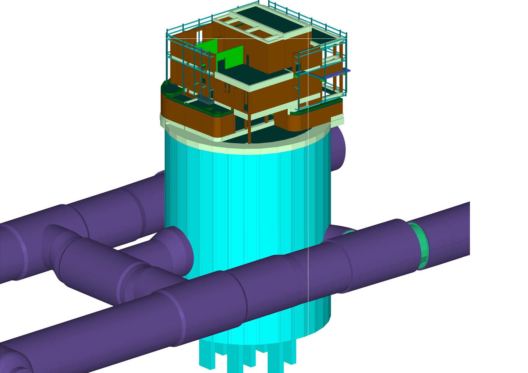
Figure 1 – Cambridge Heath Shaft 3D Model. SCL tunnels in purple 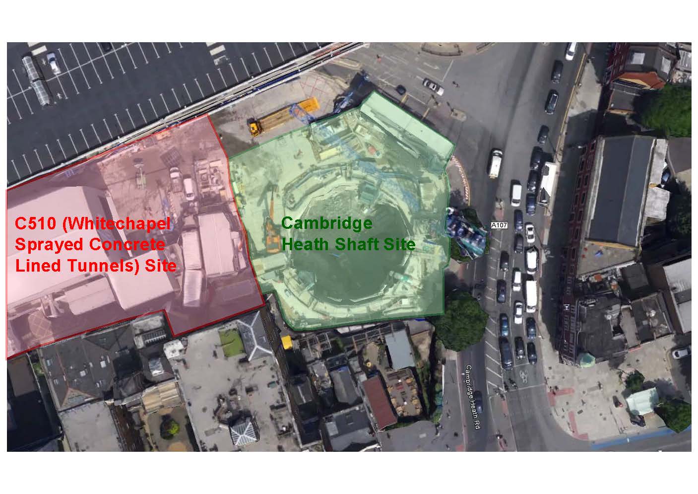
Figure 2 – Cambridge Heath Shaft Location Plan 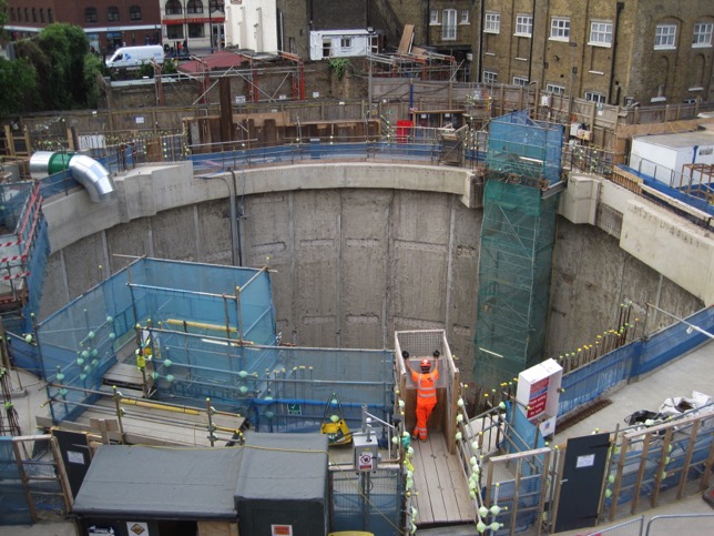
Figure 3 – Cambridge Heath Shaft from Ground Level Ground Conditions
At Whitechapel significant River Terrace Gravels overlie the London Clay to a depth of approximately 5 m with around 2 m of Made Ground above this. Below the gravels the London Clay extends to a depth below ground level of around 37 m with the Lambeth Group encountered below this. This strata is of varying width but typically 2 m-5 m approximately and comprising varying gravels, sands, silts and clays. Below this lies the Thanet Sands and chalk deeper still.
The Cambridge Heath shaft Diaphragm Walls extend approximately 8.5 m below the base slab level and therefore a few meters into the Lambeth Group. Groundwater inflow was therefore expected to be low, but depressurisation passive relief wells were drilled during the early stages of shaft excavation to allow vertical drainage up into the excavation to also mitigate the effects of possible Sand Lenses with locally raised water pressures within the London Clay.
Diaphragm Wall Design
The Diaphragm Walls at Cambridge Heath Shaft resist lateral earth and hydrostatic pressures by means of ring compression.
The Diaphragm Walls extend below formation which is to provide sufficient toe to construct the base slab. This toe also prevents short term recharge of the water table under the base slab and provides dead load against heave and hydraulic uplift. The Diaphragm Walls are 1.5 m thick and there are 32 panels of around 3 m length with a precast reinforced concrete stop end installed between every insitu panel, which was a contractor’s proposal. The chief advantage of the precast stop end is it removes the need to remove a temporary steel stop end and reduces the size of the insitu panels reducing concrete volumes and cage sizes.
Construction Phase
The final Diaphragm Wall panel layout agreed between Crossrail, the Contractor and the Designer provided for three starter panel locations spread evenly around the circumference of the shaft to ensure progress was not held up waiting for cast concrete to reach sufficient strength to excavate adjacent to.
Construction proceeded well however during the installation of Panel 28 (a standard ‘runner’ panel) when the excavation had reached a depth of around 28 m below ground level later defects were found with the reinforcement cage that could not be rectified at short notice. Since it was not possible to leave a panel excavation open longer than 48 hours as unplanned movements could occur even with the bentonite slurry occupying the excavation, the partly excavated panel had to be immediately backfilled with a weak bentonite cement, in accordance with the prepared activity plan for these eventualities. The panel was successfully constructed a few days later once the cage had been rectified.
Excavation
Following completion of the Diaphragm Walls and Capping Beam excavation proceeded rapidly down to first ring beam level at a depth of around 21 m below ground level. At this point the excavation paused to construct the RC ring beam (a 2 m deep section of the liner wall built early to ensure stability during excavation) and the lowest part of the Diaphragm Walls excavated so far to date were cleaned down.
It was at this stage that Crossrail in conjunction with both C511 and C512 undertook a visual inspection of the Diaphragm Walls to record the as-built condition1 of each panel and identify any outstanding works and defects. This inspection revealed inclusions in two panels, Panel 22 and Panel 28.
Crossrail as client immediately brought all concerned parties together to ensure a collaborative ethos prevailed so the Project Team could focus on construction safety, programme and adequacy of the permanent works when considering the defects, rather attempting to apportion blame. This collaboration was also key to the later execution of the repairs where the two contractors needed to work closely together within the shaft without mutual delay.
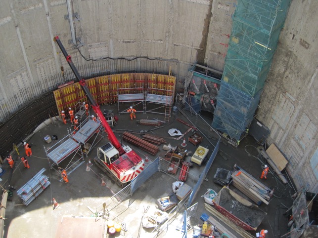
Figure 4 – Cambridge Heath Shaft with Excavation at Upper Ring Beam Level Inclusions
The two inclusions were of differing appearance. The P28 inclusion comprised a dark grey material with some resemblance to London clay. It started at a depth of around 15 m below ground level and widened to a reasonably consistent width (measured in the circumference of the ring) of around 400 mm wide. Test drilling confirmed it was fairly soft and seemed to continue for the full 1.5 m thickness of the panel, so no concrete was present within it.
The P22 inclusion was of a more variable nature. It comprised areas of rubble (brick, tile stones) within the diaphragm concrete, along with some areas of weakly concreted large stones, interspersed with areas of sound concrete. The defects occurred in a strip up to 700 mm wide from a depth below ground of around 16 m. Depth into the Diaphragm Wall was unknown but initial local investigations showed the foreign material was not just superficial. It was also masked with a skim (around 50-75 mm thick) of sound concrete for much of its area.
Both inclusions occurred at the edge of the panels generally between the cage and the precast stop end and neither had affected the installation of the cages. In the P22 case however, the cage was pushed off centre of the panel, this was however within the allowable tolerance limits.
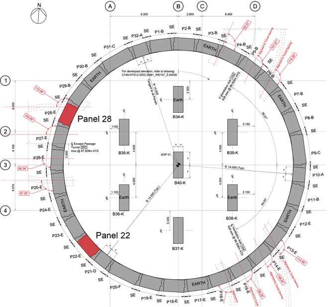
Figure 5 – Plan of CHS Diaphragm Wall Panels indicating P22 & P28 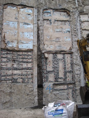
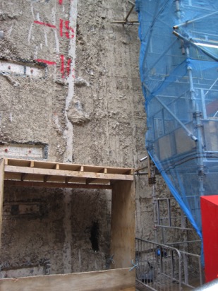
Figure 6 – Panel 28 (LHS) Inclusion & Panel 22 (RHS) Inclusion, The P22 inclusion is mostly hidden behind a skim of sound concrete
Inclusion Repair
Design Implications
Since the two inclusions prevented the development of any significant compressive hoop stresses by placing soft zones within the concrete ring where present, there was initially concern with the possibility of unplanned movements of the Diaphragm Wall panels taking place.
However the instrumentation and monitoring installed ensured the Project Team were aware of the level of stress currently in the hoop ring due to the strain gauges installed on a number of panels around the shaft. These showed the level of hoop stress in the shaft at this time was low. The shaft is designed for long term effects and worst allowable tolerances regards panel relative position, therefore it was possible to note a number of reasons for the then low hoop stress.
- The shaft was designed for a long term rising water table. During excavation passive dewatering wells were operational within the shaft and the nearby (Sprayed Concrete Lined) SCL Tunneling works had also carried out dewatering for construction resulting in reduced water pressures
- There is a period of time from excavating the shaft before the (Clay) ground around fully relaxes and brings to bear the full lateral pressure expected
- Following usual good practice and Crossrail requirements the design was carried out using ‘Moderately Conservative’ parameters so the ground in reality is likely to be better than these allowed for, as was the case
- The permanent design allowed for a new development surcharge of 75 kPa, not present at time (Construction surcharge was probably no more than 10 kPa)
- The design of the shaft needed to allow for the worst possible tolerances regards available hoop core, based on the a verticality of 1:225, which was the best tolerance the contractor was prepared to commit to. Panel installation records showed most were vertical to within a tolerance of 1 in 800 to 900, with one or two exceptions but all within tolerance and examination of the available hoop showed this to be greater than the worse allowed for which contributed in reducing the stress
- The most critical hoop stress in the Diaphragm Wall occurs after the three tunnels have been cut as stresses concentrate above and below the openings. These were not to be cut out until a later stage
Therefore the actual stress present in the shaft was low (less than 50% of trigger values) and it was clear that even if the inclusions continued down, in the short term the panels would be able to vertically span hoop stresses across the inclusions from the sound concrete higher up to a position of restraint lower down provided by the unexcavated clay within the shaft.
Methodology Development
Nonetheless it was clear the inclusions would severely compromise the strength of the shaft and would have to be repaired swiftly as the excavation progressed. At this point the Project Team therefore considered what methodology would be required for a carefully controlled repair.
As the repair would necessarily require the complete removal of foreign material and its replacement there would be for a short period a section of hoop entirely removed and reliant on the adjacent sound RC to span any hoop stress back to wherever a complete ring could be found. Therefore the principle of the repair was similar to that of a building underpinning that is to remove and repair small sections at a time.
Contract C511 as the constructor of the Diaphragm Walls undertook the repairs, in principle as a subcontractor to C512, although the repairs formed part of the defect remediation under the Crossrail C511 contract. As such C511 worked under C512’s CDM requirements and provided all necessary method statements and risk assessments for the works.
It was clear hydro-demolition be used rather than breaking as this could be set to a pressure to remove only weaker material, had greater reach than breakers in a narrow space and did not have vibration implications for operatives. It did however create high noise levels and is a dangerous tool because of its cutting abilities. Noise insulation blankets were used and operatives skilled and experienced in Hydro-demolition in a small space undertook the work.
Repair Requirements
The repairs proceeded in 1 m (measured vertically) sections from the top of the inclusions to ensure there was always sound concrete on one side of the opening. Water jetting had the additional advantage of not damaging the water bar in the precast stop end which was free to deform under the water pressure. The top face of the area removed was inclined to create a larger opening in the Diaphragm Wall at the inside face and allow air to escape from the inclusion as the grout filled the void.
The methodology required close supervision of the works by Crossrail and included intervention ‘hold points’ where C511 required sign-off of the repair to that point to proceed. These ensured all the detailed requirements of the repair methodology were adequately met. Crossrail also recorded progress through site observations and progress photos which recorded the condition of the opening within the panel during downtime in the high pressure water jetting. The hold points includes those associated with the required monitoring (see below) and also the inspection of the the faces of each section before grouting to ensure all weaker material was removed before the front shutter was fitted.
The grout was a high strength non-shrink type with a design strength equal to the Diaphragm Wall concrete (C40/50), highly flowable and poured into each section via a timber letterbox shutter that allowed the complete filling of each section with a head of 500 mm of grout and only a small surface protrusion to be removed. For waterproofing a Hydrophilic strip was fixed around the upper three sides of each repair section. When a minimum strength of 15 MPa (sufficient given the levels of hoop stress known to be present at the time) was reached, which was usually within a few days, the process could begin on the section below. Since there were two inclusions the repair team was able to alternate between the two without any lost time and all this was able to proceed simultaneously with the construction of the RC ring beam in areas of the circumference unaffected by the inclusions.
Later on, once the method was successfully established it was decided to increase the vertical depth of the repair sections from 1m to 1.5m as it was clear this could be safely done.
Employing this methodology, it was possible to repair this depth of inclusion without any delay to the programme.
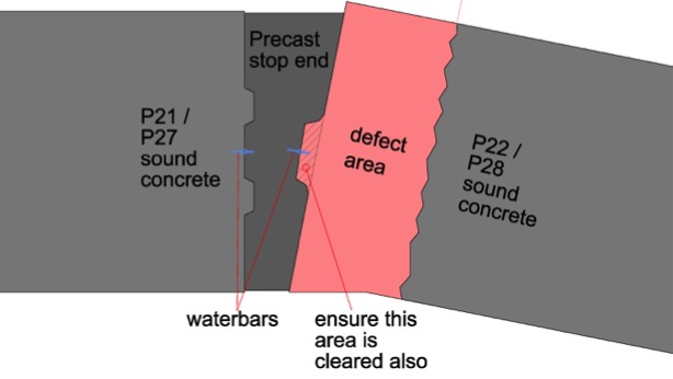
Figure 7 – Showing defect approximate extents 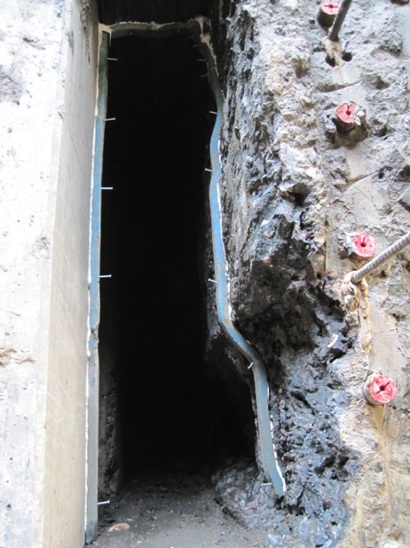
Figure 8 – Repair Section with foreign material removed & ready for front shutter fitting. Note presence of Hydrophilic strip 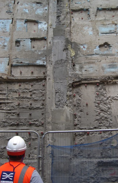
Figure 9 – Panel 28 from Upper Ring Beam Level, following repair Monitoring
Consideration was also given to monitoring of the shaft during the repair of each section.
Additional monitoring had been installed within the shaft following discovery of the inclusions which comprised survey prisms installed on eight panels in pairs facing each other to enable distortion of the shaft shape to be measured. These distances were checked from the then formation level so relative changes in the shaft shape could be measured, but not overall movement of the shaft without distortion. However inclinometers were present in the Diaphragm Walls to check this and only SCL tunnelling could have given rise to any such movements which was still a little removed from the shaft at this time.
The methodology for each section required checking the shape of the shaft before and after each section and on a daily basis. If unplanned movements had occurred it was planned that a 400 mm thick blinding slab could be cast in the shaft at short notice to form (once set) a solid disc of material to prevent further movement, however this was not necessary as all measurements of distortion taken were satisfactory. The monitoring data was also discussed at the weekly CTC meeting.
Additionally a time limit of 48 hours placed on each cast section between exposure of the precast stop end (i.e. one side of the void) and its re-covering with grout.
Groundwater
The design originally assumed that the shaft Diaphragm Wall would provide a good cut off from groundwater whilst the internal depressurisation wells would allow any water trapped within the walls to drain well ahead of the excavation.
Because the defect repairs required removal (in stages) of a complete vertical slot of the diaphragm wall there was a concern that the repair could encounter sand layers outside the shaft. This posed a low but potentially serious risk of a sudden inundation of water and associated ground movements.
A detailed investigation into ground water levels was therefore carried out looking at all the available data including that from nearby Crossrail Tunnelling operations and considering the possibility of locally raised water pressures within sand layers which meant the pressure needed to be measured within the sand strata itself and not above or below it.
These results indicated water levels in the sand layers below formation level, however the Project Team remained concerned to establish a good understanding of the geology close to each inclusion when the repairs neared formation level and the presence of sand lenses increased in likelihood.
Therefore two new boreholes were drilled inside the shaft one near to each inclusion which indicated local geology and allowed the installation of piezometers to measure water pressure. These investigations allowed repairs to continue downwards with confidence that the local geology and groundwater would not pose a problem.
Repair Logistics & Certification
The logistics for the repairs were challenging with C512 being Principal Contractor and C511 undertaking the works. Arrangements were put in place to allow C511 access to the site and the relevant method statements and risk assessments were reviewed by both Crossrail and C512.
In addition Design Check Certificates were required for the Category 2 checks undertaken for the use of access scaffolding and shuttering design. These temporary works required C512 to construct an increased thickness in blinding concrete. As the inclusion repair works advanced in depth within the shaft with the bulk excavation, a further re-sequencing of the C512 programme of works was undertaken to incorporate the additional site investigation of the lower level geology.
Continuation of the Inclusions
In addition to the on-going repairs, the Project Team also had to consider the possibility of the inclusions continuing to the base of each Diaphragm Wall panel. The panels extended 8.5 m below the final formation level so it was not going to be possible to repair a full depth defect as the excavation required would be too deep, unsafe and possibly compromise the shaft. As there was a short period available while the excavation proceeded downwards (requiring the construction of a second ring beam at a depth of around 28 m below ground level) it was decided that the designer should use this time to determine what minimum works would be needed for the long term strength of the shaft should the inclusions be found to continue below levels that could be excavated.
Meanwhile as the construction proceeded, the defects were found to continue downwards below first ring beam level and thus the repairs followed the excavation downwards allowing no more than 3 m depth of inclusion to be exposed at any time before repair was necessary to enable the dig to advance further.
Further Analysis
When considering the continuation of the defects it was evident that these would need a full re-analysis of the shaft using an adapted version of the existing 3D finite element model using the DYNA software package. A DYNA model has already been created for CHS to model the 3D effects of the SCL tunnels approaching and bypassing the shaft, but now its use enabled a full model of the inclusions to be developed.
The focus of the analysis was to determine what level the repairs should be taken down to, assuming the defects continued. However the team also understood that this practically could not be more than 2-3 m below design formation level at the most.
A new version of the DYNA model was therefore prepared that amended the strength of the P28 inclusion areas from concrete to be that of a weak clay, 0.4 MPa cube strength, and the P22 inclusion to have the strength of a very weak ‘rubble’ concrete, 2.5 MPa.
It was initially attempted to model the sequence of repair and dig (i.e. change of material of inclusion in the model back to concrete sequentially) of the inclusions from their top around 15m below ground level. However this was found to give rise to unrealistic movements in the model which were known from observations taken to this point not to be correct as the full permanent imposed loads had yet to develop, as noted above.
Therefore it was apparent the modelling needed to capture the permanent condition created by the defects under the full permanent load, in effect assuming the repairs can be carried out no impact which in practical terms was the case. Thus the defects were only included for the lengths that could not be repaired and two variant models were run, one with the repairs stopping at design formation level and the other taking them down to formation minus 3 m. The DYNA did however contain the full normal construction sequence of the shaft.
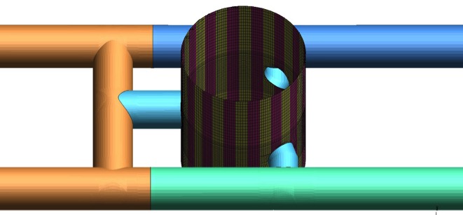
Figure 10 – Cambridge Heath Shaft DYNA model showing surrounding tunnels also Results of Analysis
Considering just the hoop compressions, the re‐analysis showed that the presence of the inclusions would result generally in a moderate reduction in the hoop compression stress in the Diaphragm Wall above the top level of the (repaired) inclusions with a corresponding increase in the hoop force in the Liner wall as the compromised Dwall is forced to grip the liner wall more tightly. This effect reduced higher up the shaft away from the defects back to normal design levels.
The general increase in hoop compression in the Liner wall was acceptable and within its capacity.
However, based on the model assuming repair only to design formation level it was found that immediately above and local to the remaining (unrepaired) part of the defects there was a very high concentration of hoop compression in the Diaphragm Wall, exceeding its stress and strain capacity as the hoop force concentrates at the nearest ‘hard point’. A potential overstress at the ultimate limit state of around 1.7 was found, because the defect was present at a position of very high hoop stresses at the base of the shaft.
Therefore as hoop stresses reduced rapidly below formation level it was proposed that the repairs would need to be taken down to a level where hoop stresses are lower to remove the overstress. It was found a repair to a depth 1.6m below formation level would be sufficient to remove the potential ULS failures, which would need to be constructed in two (one for each inclusion) local excavations of minimal & carefully controlled size, to be back filled with mass concrete.
One other finding of the analysis was that whilst the ULS effects could be made to work with the defects running full depth of the Diaphragm Wall, there was a significant increase in the in-plane bending moments in the Dwall near the top of the defects as the hoop force moved to the nearest complete full strength ring. The in-plane bending was a result of the large openings being created in the shaft for the three tunnel interfaces, and the need for the adjacent panels to span the hoop stress around these by bending in their strong axis (i.e. in the plane of the shaft wall). These revised load effects all passed at ULS, but created some significant crack width failures in bending at SLS. To resolve the Project Team applied to Crossrail to be able to carry out the SLS checks for the shaft using ‘Most Probable’ ground parameters rather than ‘Moderately Conservative’ which has been found to allow these checks to past. The strains and movements recorded in the Dwall so far supported to this concession, which was agreed in principle.
Therefore the team now had a full plan established which would enable the project to continue with minimal or no delay and ensure the long term strength and durability of the shaft, should the defects be found to continue.
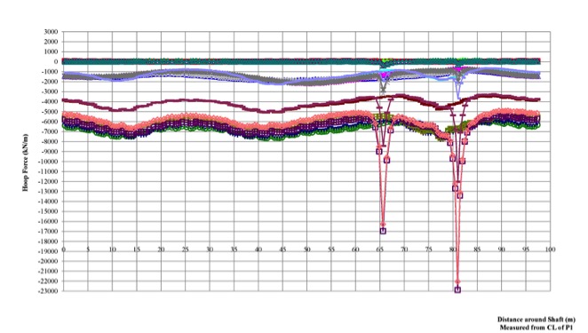
Figure 11 – Showing Hoop Stress at formation level around circumference of CHS. The two peaks show concentrations of Hoop stress immediately above each inclusion. This model assumed repair down to formation level only 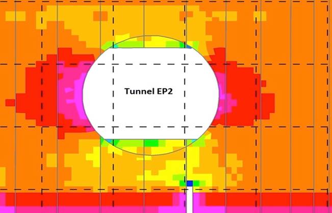
Figure 12 – Elevation on the larger of the two peaks above. The inclusion can be seen at the bottom of the image with the concentration of stress (blue patch) at the base of the repair Base of Inclusions
The excavation of Cambridge Heath Shaft had continued in parallel with the design work described above. As it had done so the P28 inclusion was found to continue downwards with a consistent width and appearance. The P22 (rubble) inclusions also continued downwards increasing in size to up to 700 mm wide (with the cage pushed to the other side of the panel) and inconsistent material.
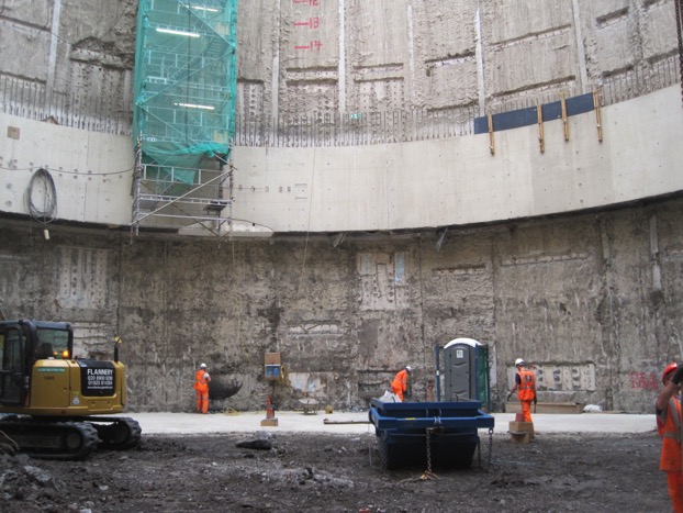
Figure 13 – Cambridge Heath Shaft from Lower Ring Beam Level 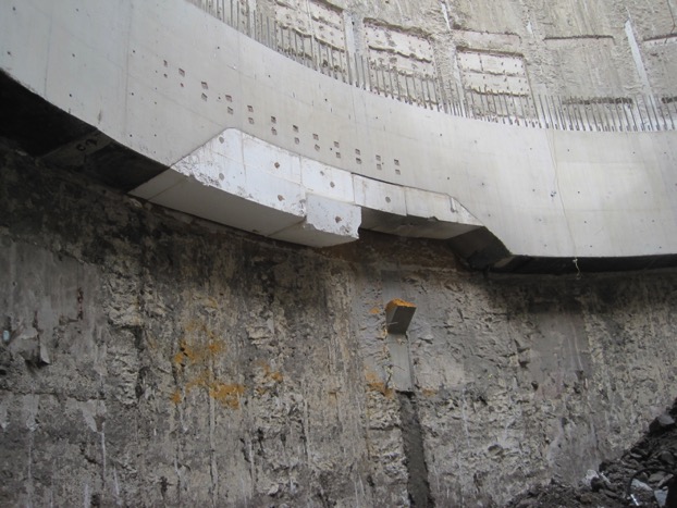
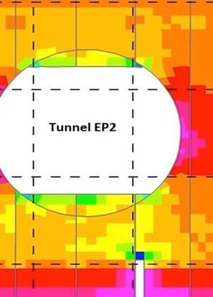
Figure 14 – P28 partially repaired below Upper Ring Beam. The cast projection from the letterbox shutter is yet to be removed. The top of the opening for Tunnel EP2 can also be seen. However once the dig reached a depth of around 28 m below ground level, just below the second ring beam the P28 inclusion was found to abruptly stop with a flat base. At this point the panel construction records were re-examined and it was established that material forming the inclusion was a wedge of bentonite cement from the earlier abortive panel excavation. This had reached too high a strength for the excavator grab to remove on the re-excavation and had a steeply inclined (near to the vertical) top indicating the grab had slip up and down it as the second dig had proceeded leaving a 400 mm wide wedge in place, but only down to the depth of the first dig.
It was clear at this point that the P28 inclusion would not continue downwards. However it was also clear that the analysis work undertaken was necessary to consider the effects from the less predictable P22 inclusion. The causes of this inclusion were not fully understood, but it is believed the brick and tile material must have come from the made ground near the top of the panel.
The P22 inclusion continued down to a point just below formation level of the shaft excavation (32 m depth below ground level) where sound concrete was found once more between the cage and the precast stop end, and concrete cores were taken and crushed that confirmed this.
Figure 15 – P22 just below formation level in local dig. Repair to formation in view with good concrete found just below this. Local Borehole / piezometer also visible Therefore no further repairs below formation level were needed. However the work done was necessary to mitigate the risk of delays on a programme critical shaft.
Conclusions
The panel defects found at Cambridge Heath Shaft arose from different causes. The P28 defect could theoretically have been removed if a weaker bentonite cement had been used for the initial backfilling, although it must be acknowledged that it is very difficult to strike just the right balance between strength for support and weakness for re-excavation, especially in the rushed circumstances requiring a panel back filling and given the increase in strength over time. However the option to backfill an unsuccessful panel excavation must be retained to prevent unplanned movements.
It is more difficult still to determine the necessary corrective actions to prevent the re-occurrence of a rubble inclusion such as P22. A locally deeper guide wall might benefit, or temporary steel casing if size allows. However the unpredictability of the made ground makes it difficult to pre-plan such precautions. Smaller areas of superficial rubble were observed elsewhere on the exposed Diaphragm Wall inside face, however it was only on one panel out of 32 that they formed full observable defects.
The Crossrail, Contractor and Designer team worked successfully together to swiftly develop a plan to allow construction to continue and the faults to be rectified. A further plan to mitigate against the unknown extent of the inclusions was also developed. Although this was not eventually required both elements of the response to the defects allowed programme certainly from this item to be maintained and Cambridge Heath Shaft to continue to be constructed.
References
- Crossrail Report – CHS Defect Schedule
-
Authors

