Reinforced Shotcrete with Bar Diameters up to 32mm
Document
type: Technical Paper
Author:
Martin Fischer, Matthias Hofmann, ICE Publishing
Publication
Date: 07/09/2015
-
Read the full document
Project Introduction
The Crossrail project in London with an overall project value of about £16 billion is currently the largest infrastructure project in Europe. It includes the construction of a 118 km long regional commuter railway line, which will link the surroundings to the west and east of the capital with Central London. Furthermore, it will improve the connections to Heathrow and Canary Wharf.
The core piece of the project is the 2 x 21 km long tunnel route crossing Central London with 8 underground stations 5 of which are built using the Sprayed Concrete Lining (SCL) Method.
Contract C510 comprises the construction of two SCL stations, Liverpool Street and Whitechapel, awarded for £ 240M to the BBMV Joint Venture, formed by Balfour Beatty (UK), BeMo Tunnelling (AUT), Morgan Sindall (UK) and Vinci Grand Projects (FRA).
Project Requirements on Reinforced Shotcrete
Based on the safety requirement that no one should be below unsupported ground at any time, the construction stages for bar reinforced areas as e.g. at tunnel junctions at the station tunnels on Crossrail were the following:
- Construction of the primary lining of the parent tunnel with steel fibre reinforced concrete
- Construction of a primary lining thickening in required areas inside the already existing primary lining (e.g. around openings of child tunnel) to accommodate required bar reinforcement in a safe environment
- Breakout of child tunnel or other structures once the thickening gained its full strength
Due to the absolute priority of safety during all construction stages and related structural requirements (e.g. 120 years lifetime) it became necessary to install reinforced shotcrete with bar diameters up to 32 mm. Planned quality control through coring of the structure in the very early construction stages identified shadowing in some areas which initiated a study to find the maximum possible bar sizes to be sprayed in for permanent works. Therefore large scale trials with bar diameters bigger than 14 mm have been carried out prior installation and analysed systematically according to ACI 506.2-95 “Specification for Shotcrete” [1].
Set-Up for Large Scale Trials on Crossrail C510
Trial Set-Up
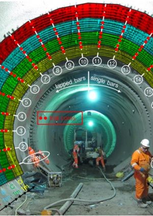
In order to investigate all possible influences and impacts of different bar diameters and bar arrangements large test fields have been set up around the tunnel circumference in one of the approximately 6 m diameter temporary pilot tunnels of the station platform tunnels (see also Figure 1).
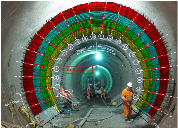
Figure 1 – Overview on Trial Arrangements for one of the Test Fields
The following factors for shotcrete quality have been tested:
- Influence of different bar diameters of B16mm, B20mm, B25mm and B32mm
- Influence of different bar spacings of 75 mm, 100 mm, 150 mm, 200 mm for B16 and B20 crossed by B16 every 150 mm
- Influence of overhead vs. sidewall spraying
- Influence of lapping bars vs. single bars.
The reinforcement offset from the tunnel wall was limited to a minimum 2.5 x diameter and a target maximum offset of approximately 125 mm.
Shotcrete Mix Design and Application
In order to best encapsulate large diameter rebar, a shotcrete mix with a very moderate strength gain development (around J1 curve according to Austrian Sprayed Concrete Guideline [2]) and a high remaining workability in the first seconds after application had to be developed.
For the trials a mix with 420 kg/m³ CEM I 52.5 N Castle / Ketton, 6% Microsilica and BASF SA160 accelerator (dosage between approx. 3 and 6%) has been applied through a Meyco Potenza robot.
The accelerator product used was originally developed as one of the first alkali-free suspensions of accelerators and is nowadays more and more replaced by faster setting accelerator products. The product basically consists of aluminium sulphate and organic components for gluing effect. The general behaviour is a very slow reaction in the early phase (up to about 1h) and good strength gain thereafter.
Based on the findings of the trials, BBMV’s accelerator supplier BK Giulini developed the F2000CR accelerator, a product for shotcrete encasing reinforcement, with a behaviour similar to SA160. This new product contains an inorganic retarder, which is active in the first 10 -15 minutes with no effect on the further strength development.
Applied Test Criteria
About 400 cores have been taken from all test fields and each core has been reviewed and classified by a joint expert team according to the ACI 506.02-95 core grade definitions (see also illustrated in figure 2).
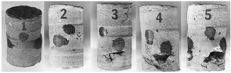
Figure 2 – Core grade illustration as per ACI 506.02-95 [1]
As seen from Figure 2 the ACI 506.02-95 basically defines 5 grades of core quality from grade 1 (good) to grade 5 (poor). The grades are descripted as follows:
- Grade 1: Shotcrete specimens are solid; there are no laminations, sandy areas or voids. Sand pockets, or voids behind continuous reinforcing steel are unacceptable.
- Grade 2: Shotcrete specimens shall have no more than two laminations or sandy areas with dimensions not to exceed 1/8 inch thick by 1 inch long. Porous areas behind reinforcing steel shall not exceed 1/2 inch in any direction except along the length of the reinforcing steel.
- Grade 3: Shotcrete specimens shall have no more than two laminations or sandy areas with dimensions exceeding 3/16 inch thick by 11/4 inch long, or one major void, sand pocket, or lamination containing loosely bonded sand not to exceed 5/8 inch thick and 11/4 inch in width.
- Grade 4 core: The core shall meet in general the requirements of Grade 3 cores, but may have two major flaws such as described for Grade 3 or may have one flaw with a maximum dimension of 1 inch (25 mm) perpendicular to the face of the core with a maximum width of 11/2
- Grade 5 core: A core that does not meet the criteria of core grades 1 through 4, by being of poorer quality, shall be classified as Grade 5.
As acceptance criteria it defines that:
a) a mean grade for min. three test specimens of 2.5 or less is acceptable unless otherwise specified and
b) individual shotcrete cores with a grade greater than 3 are unacceptable.
Trial Results
After undertaking numerous large scale trials over a total trial area of about 300 m2 tunnel lining with about 400 cores taken, the following trends on the impact of different reinforcement diameters and different reinforcement arrangements can be identified:
Impact of Rebar Diameter
The results in Fig. 3 clearly show, that the rebar diameter provides a big impact on the quality of rebar encapsulation. When looking at the two indicators of mean value of core grading according to ACI 506.2-95 as well as the percentage of cores above core grade 3 (unacceptable according to ACI 506.2-95), a clear trend can be identified. These results include an average on all cores taken including laps, overhead spraying and varying rebar distances.
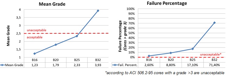
Figure 3 – Comparative Results on Key Core Quality Indicators for Different Bar Diameters
With a mean grade of 1.23 and only 2.6 % of encapsulation failure (including laps, overhead spraying and all varying rebar distances) B16mm rebar can be sprayed under all circumstances to the quality criteria required, given that good workmanship and the right mix design is applied.
B20mm rebar has an acceptable mean grade of 1.79 (<2.5 as per ACI 506), but an average of 8.8% of encapsulation failure. The failure rate increases in special areas like lap zones of bars (14.5%) or in the tunnel crown (13.0%).
Depending on the designer’s evaluation, B20mm with an encapsulation failure of approx. 10 to 15 % may be acceptable for short term durability (at least primary lining works duration) and may have to be evaluated for acceptance for permanent works requirement. This approach may be considered in areas, where the design requires vast amounts of reinforcement and an alternative requirement of multiple layers of preferred B16mm may have a more detrimental influence on the overall lining quality.
B25mm rebar with an overall failure ratio of 17.1 % and a failure ratio of up to 40.0 % in lap zones shall only be used in special locations, where no alternatives exist. In this case the designer will need to be aware of the risk of shadowing and consider it in the design.
B32mm rebar shall be avoided, especially in special arrangements as laps and in overhead areas. Due to the limited amount of cores available for this specific bar size (8 No from one test field) the exact results may vary due to increased statistical spread, however, a clear trend of an average mean grade of above 2.5 as well as a failure ratio of above 50 % can be identified (most failures occurred at laps, where the failure rate was nearly 100 %).
Impact of Rebar Arrangement / Spacing
For the B16 and B20 test fields the influence of different rebar spacing has been evaluated. It was expected, that a larger spacing would benefit the quality of the encapsulation. The results in Fig. 4 show, that within statistical variance no trend can be seen for improved quality with increased spacing of the rebar. However, a certain minimum spacing shall still be applied to be able to physically spray through the reinforcement.
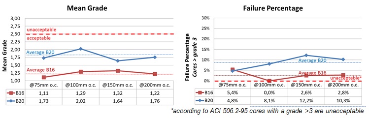
Figure 4 – Mean Core Grading / Failure Percentage for different rebar spacing
Impact of Lapping Bars
Generally, as expected, a lap has a detrimental influence on encapsulation as it doubles the bar thickness to spray around in this particular location. Whereas bar diameters of B16 and below can cope with encapsulating a lap, a clear decrease in core quality (mean value) and increase in core failure (failure percentage) can be identified with rebar diameters above B16, as shown in Fig. 5. The reduction in quality and the increase in core failure develop in an exponential function with increasing bar diameter.
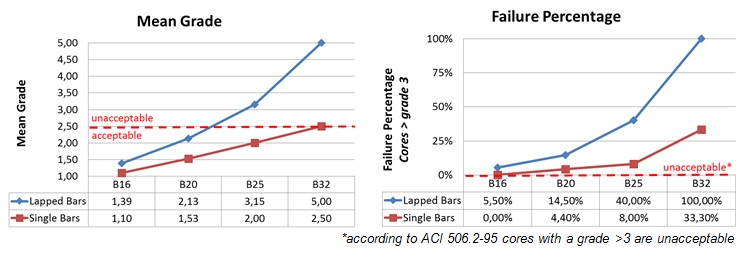
Figure 5 – Mean Core Grading / Failure Percentage on lapped bars for different bar diameters
Overhead Spraying
To spray successfully overhead, the accelerator dosage needs to be increased. This compromises the encapsulation quality as the mix as sprayed is not as workable as necessary to flow around the reinforcement. This trend can be clearly seen in Fig. 6 where the results for the B16 and B20 test fields have been analysed.
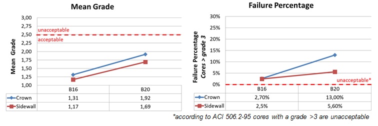
Figure 6 – Mean Core Grading / Failure Percentage on Sidewall vs. Crown
Impact of shadowing on the load capacity of the lining
The main impact of shadowing on reinforced shotcrete is that bond stresses are reduced. Bond between reinforcement and concrete is necessary to ensure composite interaction of the two materials. To assess the influence of lower bond strength on the structural behaviour the bond theory in reinforced concrete is briefly summarised following the lines of [3-6]. Then the influence of shadowing on the structural behaviour and possible remedies at design level are discussed.
It must be pointed out that no experimental data were available for bond behaviour of shotcrete with shadowing behind rebars. Thus the following is an attempt to assess the consequences of shadowing on the structural response. Experiments (e.g. pull out tests) are necessary to verify the findings.
Bond Behaviour
In reinforced concrete construction, efficient and reliable force transfer between reinforcement and concrete is required for optimal design.
Bond strength initially results from chemical adhesion between steel and hardened cement, but this resistance can be overcome at very low stress levels. Once slip occurs, friction contributes to bond. In plain round bars, this is the major component of strength. With ribbed bars, under increasing slip bond depends principally on the bearing, or mechanical interlock, between ribs and the surrounding concrete (see Fig. 7). The forces on the bar surface are balanced by compressive and shear stresses on the concrete contact surfaces, which are induced into tensile stresses that can result in cracks.
![Figure 7: Bond force transfer mechanisms according to [3]](https://learninglegacy.crossrail.co.uk/wp-content/uploads/2016/08/7D-004-Figure-7.jpg)
Figure 7 – Bond force transfer mechanisms according to [3]
Bond Stresses
Simplified bond stress may be regarded as a shear stress over the surface of a bar, although bond, anchorage, development, and splice strength are structural properties, dependent not only on the materials but also on the geometry of the reinforcing bar and the structural member itself.
As a consequence bond stress-slip laws are based on experimental results. A typical bond stress-slip curve is given in Fig. 8.

Figure 8 – Bond stress – slip relationship according to CEB-FIP Model Code 1990 ([4])
Bond stress typically increases with slip up to a peak value tmax. If slip is increased further bond stress decreases to a residual value tf.
The distribution of bond stresses along the bar is nonlinear. Since the distance between the cracks and the amount of tensile load carried by concrete varies, the real distribution of bond stresses along the length of a bar cannot be predicted. Thus in the following bond stresses were considered uniform over the developed or spliced length of the reinforcement.
Impact of shadowing on load capacity of the lining
Because of the unpredictable nonlinear distribution of bond stress along a rebar most international codes of specifications (ACI, Eurocode) use the concept of development length rather than bond stress. The main requirement for safety against bond failure is to provide a sufficient extension of the length of the bar beyond the point where the steel is required to develop its yield stress and this length must be at least equal to its development length.
According to [6] the bond strength fbd is
fbd = 2.25 x η1 x η2 x fctd (1)
η1 and η2 are factors for consideration of bond quality and bar diameter respectively. fctd is the design value of concrete tensile strength. The required development length lb,req follows from equating the bond force Fb with the rebar force Fs (assuming yielding of the bar, design value of yield strength fyd):
Fb = Fs (2)
fbd x ds x π x lb,req = fyd x ds2 x π / 4 (3)
lb,req = ds/4 x fyd/fbd (4)
Shadowing behind rebars reduces the bond capacity. As a remedy to ensure composite interaction of rebars and concrete the development length can be increased. Formally this may be done along the lines of Eurocode 2 [6] by reducing the factor for bond quality η1 of equation (1). E.g. if the percentage of grade > 2,5 according to ACI 506 [1] is 30 %, then the development length should be increased by approximately 30 %.
For the sprayed junction with 32mm bars which showed shadowing in some areas and initiated these trials, the design was reviewed and considered acceptable for the temporary condition because the short term value of fctd is considerably larger than its long term value. For the permanent (long term) condition modifications were made to strengthen the secondary lining to compensate for the reduced bond and strength of the primary lining in the long term.
Note that this is a first attempt to describe the influence of shadowing. Experiments and further scientific work shall be undertaken to check if this simplistic approach is appropriate or not.
Impact of shadowing on durability
The alkaline environment surrounding reinforcement in sound fresh concrete results in formation of a passivating layer on the surface of reinforcement which effectively prevents corrosion [4]. Requirements for corrosion are the breakdown of the passivation film, moisture in the concrete to act as an electrolyte and availability of oxygen. Due to shadowing these essential conditions for corrosion may be present and thus it is more likely that bars corrode. For the long term behaviour of structures this may be an issue.
Conclusions
The decision on the maximum rebar size to be sprayed in basically depends on two requirements, the required load bearing capacity and the required durability of the system.
Given that the right mix design and workmanship is applied, B16mm rebar can be sprayed to the required quality criteria for permanent works.
Depending on the designer’s evaluation, B20mm may be acceptable for short term durability (at least for temporary primary lining works) and may have to be evaluated for acceptance for permanent works requirement. This approach may be considered in areas where the design requires vast amounts of reinforcement and where an alternative requirement of multiple layers of preferred B16mm may have a more detrimental influence on the overall lining quality.
B25mm rebar shall only be used in special locations, where no design alternatives exist. In this case the designer will need to be aware of the risk of shadowing and consider it in the design.
Rebar sizes above B25mm shall be generally avoided when possible.
However, the conclusions made are valid for the specific trials undertaken only. In case it can be demonstrated in different circumstances that adequate encasement of larger bar diameters above B25mm can be achieved, different standards may be applied.
These findings also tie in with previously published literature documentation as e.g. the Austrian Sprayed Concrete Guideline [2] which recommends under clause 8.2 “as a rule, the diameter of secondary reinforcing bars should not exceed 14 mm” or the Shotcrete International Building Code 1913 [7], which recommends “…[1913.4.1] The maximum size of reinforcement shall be No. 5 bars [comment: #5 bars = 5/8“ = 15.8 mm] unless it is demonstrated by preconstruction tests that adequate encasement of larger bars will be achieved.”
References
[1] ACI 506.2-95, Specification for Shotcrete, American Concrete Institute, 2003
[2] ÖBV: Guideline Sprayed Concrete. Vienna, 2013.
[3] ACI 408R-03, Bond and Development of Straight and Reinforced Bars in Tension,
ACI Committee 408, American Concrete Institute, 2003
[4] Fédération internationale du béton (fib): Structural Concrete, Textbook on Behaviour, Design and Performance
Updated knowledge of the CEB/FIP Model Code 1990, Volume 1, CEB/FIP, 1999
[5] Fédération internationale du béton (fib): Bond of reinforcement in concrete, CEB/FIP, 2000
[6] EN 1992-1-1: Eurocode 2: Design of concrete structures
Part 1-1: General rules and rules for buildings
[7] ICC, International Building Code, Section 1913, 2006
-
Authors

