Robotic Application of a 50 mm Thick Sprayed Concrete Fireproofing Layer
Document
type: Technical Paper
Author:
Edward Batty MEng, Eleanor Kentish MEng, Alan Skarda MA MEng CEng MICE, ICE Publishing
Publication
Date: 31/08/2016
-
Read the full document
Introduction
Fire is one of the most serious risks to a tunnel. The nature of tunnels — being long enclosed spaces — can increase the intensity of a fire, and make fire-fighting and rescue operations difficult. The damage that can be caused has been demonstrated by a number of historic tunnel fires, such as the Channel Tunnel fires of 1996 and 2008, and the Mont Blanc Tunnel fire in 1999.
Without any intervention, the high temperatures in a fire create thermal stresses and a build-up of vapour pressure within the pores of concrete, which eventually exceed the tensile strength and trigger explosive spalling. Spalling exposes the core of the section to severe temperatures, leading to a loss of concrete and steel reinforcement strength or further spalling of successive layers. The concrete used in tunnel linings is particularly susceptible to explosive spalling, due to its low permeability achieved by the addition of microsilica.[1]
The sprayed concrete lined (SCL) tunnels on Crossrail have been designed to resist the worst anticipated fire in operation, in order to prevent collapse and minimise damage to the structure. The design called for a system of passive fire protection, the efficacy of which was validated by the contractor through a testing regime. It was critical that the application on site reflected the test conditions, which demanded special control on the profile and thickness of the lining. In order to meet these constraints on tolerances and quality, BAM Ferrovial Kier joint venture (BFK) developed a reliable method of working with the Meyco Logica spraying robot, and a bespoke survey system for accurately checking thicknesses in the field. These innovations are the focus of this paper.
Specification
Crossrail Design Standards specify the inclusion of micro synthetic fibres in concrete for tunnels and shafts. Such fibres eliminate or significantly reduce the depth of spalling in a fire, by disintegrating and allowing high pore pressures to dissipate. While these fibres do not directly protect the structure from heat damage, they ensure that the surface layer remains largely intact and functioning as a thermal barrier, to shield deeper layers of concrete and steel reinforcement.[2]
The fire design of the SCL tunnels at Bond Street consists of a sprayed structural concrete regulating layer containing micro synthetic fibres. The tunnel linings therefore consist of the following layers (Figure 1):
- Primary lining with either steel fibre reinforcement (SFR) or bar reinforcement;
- Regulating layer and sprayed waterproofing membrane;
- Secondary lining of 150–250 mm minimum thickness with either SFR or bar reinforcement;
- Fire regulating or fireproofing layer of 50 mm minimum thickness containing (micro synthetic) monofilament polypropylene fibres.
Aside from providing passive fire resistance, the fireproofing layer covers any protruding steel fibres in the secondary lining to protect future personnel in the tunnels. It also contributes to the structural capacity of the lining, although it does not have the same level of residual flexural strength as the SFR layers.
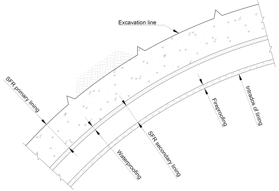
Figure 1 – Simplified illustration of the sprayed concrete lined tunnels at Bond Street While developing the fireproofing mix design, BFK carried out a programme of testing in accordance with Crossrail’s KT24 specification — based on a modified version of the EFNARC guidelines[3] — in order to demonstrate that the design would perform when exposed to a EUREKA fire curve. Apart from the importance of testing the overall mix (which may be affected by other factors such as aggregate type), it was essential to demonstrate that the proposed design of a steel fibre reinforced secondary lining (without micro synthetic fibres) topped with a 50 mm thick fireproofing layer would still perform, given that previous tests[2] had used micro synthetic fibres throughout their slabs or segments.
A replica of the lining in Figure 1 was constructed as a slab and fire tested. After being subjected to rapid heating up to 1200 °C as part of the EUREKA curve, the fireproofing layer successfully resisted spalling and protected the lining. The temperatures of the waterproofing and reinforcement remained below 250 °C and 450 °C respectively, while cores showed that the residual concrete strength was greater than 70 % of the 28 day strength — thus meeting all criteria of the specification. This verified that the designed concrete mix, dosed with 1kg/m³ monofilament polypropylene fibres and applied in a layer thickness of 50mm, would be sufficient to resist the specified fire loads.
These fire tests set the benchmark for a 50 mm thick layer. While the test slabs were produced in controlled conditions, applying this fireproofing layer on site to a tunnel lining presented many challenges. Significantly, a limited tolerance had been allowed for in the design so that if the lining was too thick, it would encroach on the inner design radius. This would not be acceptable for spaceproofing reasons.
On the other hand, as-built thicknesses less than 50 mm were not supported by the fire tests. Notwithstanding the tolerances available, simply spraying another layer of fireproofing on top would introduce an additional cold joint and hence a weaker interface in the lining. Given that explosive spalling occurs when the tensile strength is exceeded, the behaviour of the resultant lining in a fire would be uncertain.
It was therefore extremely important that the 50 mm thick fireproofing layer could be applied to the highest accuracy, in order to achieve the minimum thickness in a single operation and without encroaching on the internal design line.
The Challenge
Traditionally, the penultimate layer of a tunnel was trimmed to the correct profile if required, and a flash coating of fine aggregate high flow wet mix concrete was hand sprayed and screeded to form the final profile. The use of physical guides such as screed rails, profile bars or depth pins in a hit and miss bay sequence ensured the required thickness and defined profile were met. Finishing sprayed concrete in this manner was time consuming and had inherent health and safety risks.
Given recent technological developments, these traditional methods of controlling thickness and profile are now rarely used. The current preferred method for applying sprayed concrete uses remote-controlled manipulators or spraying robots, where the nozzleman controls the pump rate, accelerator dosing and air volume through the robot. This method of application provides faster and safer placement mechanisms over the traditional hand spraying technique.
While spraying with these robots, the SCL profile is controlled by an engineer using a total station. Existing survey systems use an alignment string stored within the software that represents the centreline of the tunnel section. The programme includes a series of profiles which denote the theoretical design shape of the tunnel. Measurements are taken by the engineer, while the software generates horizontal and vertical offsets from the centreline, and a radial offset from the theoretical design profile. Using this system the thickness is ensured by spraying to a predetermined radial offset, which is calculated based on the as-built of the previous layer.
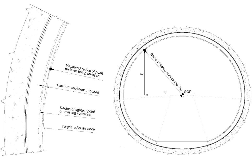
Figure 2 – Diagram showing existing system of profile control, which measures a point on the lining, calculates the radius to the SOP and compares it to the design radius at that point. Trials undertaken by BFK to assess the feasibility of these existing systems for fireproofing application identified a number of drawbacks:
- Manual spraying of the fireproofing layer resulted in inconsistent layer thicknesses.
- Due to the uneven profile of manually sprayed concrete, the engineer had to check a large number of points on the lining to ensure compliance. This presented a high likelihood that areas of inadequate profile would be missed. If under-thick areas were later identified, the full bay might have been milled out and reapplied.
- If an area without the required radial offset was identified then spraying additional concrete onto this area resulted in overspray onto the surrounding areas. If this overspray encroached onto the design radius, it might have required trimming back.
The limitations in existing systems stem from the manual control of the spraying robot, the reliance on the skill of the nozzleman to spray an even layer of concrete and the engineering survey control. In an attempt to increase the consistency of the application of this layer, BFK procured a state of the art spraying robot.
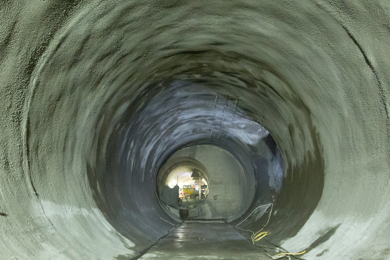
Figure 3 – Photograph showing undulations in SCL profile as a result of manual spraying. Automatic Robotic Spraying
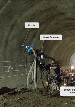
The spraying robot selected by BFK for fireproofing application was the Meyco Logica. The Logica is equipped with a number of advanced features, which allow the user to apply a uniform layer of sprayed concrete with a high degree of accuracy.[4]
The robot has a number of integrated systems. These include a series of sensors, which continually monitor the position of the boom relative to the centreline of the chassis, and a boom mounted laser scanner which can survey the position of the tunnel profile in a given working envelope to an accuracy of 10 mm.
The information collected by these systems is processed by an integrated computer. The computer is the driving force behind the spraying robot’s advanced features. When instructed it can control the kinematics of the nozzle automatically, with little input from the nozzleman.
While spraying in automatic mode the nozzle of the spraying robot travels on a pre-determined route of horizontal passes with consistent circumferential spacing (Figure 4). The manner in which the nozzle travels on this route can be pre-defined and fixed. This allows the thickness of concrete applied to be calculated using a series of relationships (Equations 1 to 3).
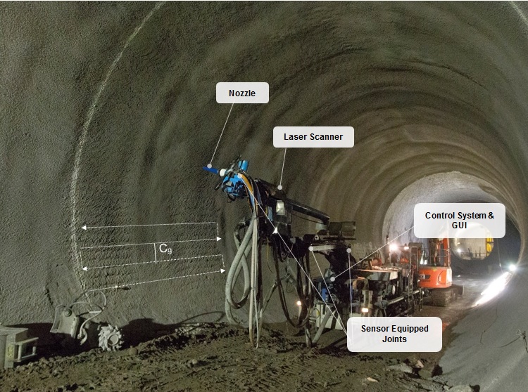
Figure 4 – Illustration showing the pre-determined route of the Logica’s nozzle. Dt [m] = 1 ⁄ Cg (1)
Where Dt [metres] is the horizontal distance travelled by the nozzle to cover 1 m2 of the tunnel profile;
Cg [metres] is the circumferential gap between horizontal passes.
Tm [sec] = Dt / Ms (2) Where Tm [seconds] is the time required for the nozzle to cover 1 m2 of the tunnel profile;Ms [metres per second] is the travel speed of the nozzle.
Th [mm] = Tm X Pr (3) Where Th [mm] is the thickness applied per 1 m2 of the tunnel;Pr is the concrete pump rate [m3 per second].
Once these parameters had been determined, the robot was set up for automatic spraying. The following points briefly describe the process adopted by BFK for a typical set up in an SCL tunnel of 10 m diameter.
- Position and stabilise the Logica on the cast in situ invert.
- Define the working envelope using the on board laser scanner. Mark each bay with four points at the interface between the cast in situ invert and SFR shotcrete profile to create a 2 m long bay.
- Scan the existing profile of the working envelope. This typically took 2–3 minutes to complete in a 10 m diameter tunnel.
- Define the parameters for automatic spraying.
- Commence spraying in manual mode with the nozzle directed away from the profile, and once a steady flow of concrete is observed engage automatic mode with the manipulator’s remote control.
- Monitor the automatic spraying process until the fireproofing layer has been applied to the whole working envelope.
Before starting full scale production, BFK carried out a series of trials to gauge the accuracy of the manipulator given a baseline set of parameters. During these trials it was found that — in addition to the variables previously described — the layer thickness achieved was also dependent on the performance of the spraying robot’s concrete pump.
The operational efficiency of a concrete pump is highly dependent on the workability of the mix being sprayed. Given a mix of high workability, a greater volume of concrete enters the pistons prior to each stroke of the pump, which in turn leads to high operational efficiency. Conversely, for a mix of low workability a reduced volume of concrete enters the pistons, which leads to decreased operational efficiency.
It was concluded that, given the average workability (550 mm flow) of the fireproofing mix delivered to site, the concrete pump of the spraying robot was approximately 70 % efficient when compared to the specified pump rate. To account for this inefficiency, the theoretical thicknesses calculated using Equations 1–3 were multiplied by a correction factor of 0.7. Furthermore, the trials confirmed that, given the range of concrete workability accepted on site (620–480 mm flow), an additional deviation of ±15 mm from the corrected theoretical thickness was expected.
These additional factors and the observed accuracy of the manipulator in early trials resulted in a target thickness of 70 mm being selected for all tunnels. The baseline settings used to achieve this thickness comprised a concrete pump rate of 10.3 m³ per hour, a circumferential gap of 0.1m, and a nozzle travel speed of 0.29 m/s.
Bespoke Survey Software
During the application of the fireproofing layer, the formulae detailed previously provided the primary method for controlling thickness. However, given the importance of achieving the minimum 50 mm throughout, it was paramount to continuously validate the manipulator in the field.
On completion of the bay, the spraying robot provided the option to re-scan the working envelope; by doing this, the thickness of the layer applied was calculated by comparing pre and post spray scan data. This system was trialled at Bond Street and a number of drawbacks were identified.
As Figure 5 shows, overspray occurred at the beginning and end of each bay during the automatic spraying process. As this overspray had the potential to encroach on the design radius, it was necessary to leave a small gap between the previous and current working envelopes. Leaving a gap meant the area could not be checked by the spraying robot and a risk of underspray was introduced. This gap left between bays remained unchecked until a detailed as-built was taken of the tunnel some hours later, by which time application of additional fireproofing mix to nonconforming areas was not possible due to hardening of the previous layer.
In addition to the above, the data from these thickness checks was stored relative to a local co-ordinate system and would be lost given any movement of the machine. This was undesirable since accidental movement of the machine would have resulted in sections of the tunnel not being checked.
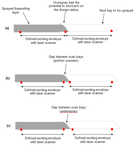
Figure 5 – Scenarios at the joints between bays: a) overspray b) perfect spray c) underspray. To overcome these drawbacks and to further refine the spraying process, BFK developed a bespoke piece of survey software able to check the thickness of the fireproofing layer applied, instantly and independently of the spraying robot.
The software, named ‘Tunnel Onions’, was developed to compute the applied thickness of the fireproofing layer by comparing real time survey data from a total station to a point cloud of the previous layer. The software was loaded onto a hand held tablet and linked to the total station using a Bluetooth connection.
The as-built of the SFR layer was captured using a laser scanner, resulting in a high density and randomly spaced point cloud of the tunnel lining. However, given the nature and speed in which the calculation of thickness needed to be carried out, pre-processing of the point cloud into a regularly spaced and low density grid was essential prior to use. The software carried out its determination of thickness with a 2D calculation (Figure 6).
In addition to the SFR point cloud, the design profile of the tunnel was also loaded onto the software. Through the combination of these points of reference, the engineer could monitor both the thickness of the fireproofing and the position of the profile simultaneously throughout the spraying process.
Following successful trials that validated the performance of the spraying robot and survey software, application of the fireproofing commenced. Over a 5 month period, 1 km of tunnel was successfully sprayed using these systems, achieving a fireproofing thickness ranging from 60–90 mm.
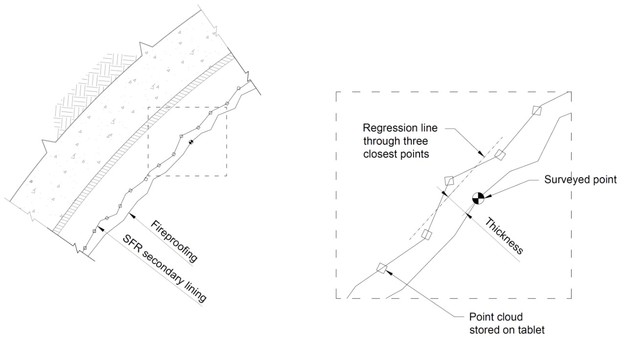
Figure 6 – Diagram showing calculation of ‘Tunnel Onions’ software. Conclusions and Recommendations
Following a number of historic tunnel fires, modern design standards specify the inclusion of micro synthetic fibres in concrete tunnel linings for passive fire resistance. The fire design of the SCL tunnels at Bond Street consisted of a 50mm thick regulating layer applied over the secondary lining. This was validated by fire tests and had to be applied in a single operation, without overspraying and encroaching on the inner design radius.
Over the past decade, advances in spraying technologies and survey software have removed the need for physical guides in order to control the profile and thickness of sprayed concrete linings. However, these systems struggled with the consistent application of this fireproofing layer. A much greater tolerance would have to be allowed for in the design for these systems to be successful in the future.
At Crossrail’s Bond Street Station, the use of a state of the art automatic spraying robot provided a clear increase in sprayed concrete accuracy and consistency when compared to manual spraying. However, the technology had a number of drawbacks and the need to check the thickness of SCL applied in the field was evident. Through the development of point cloud based software able to carry out this thickness calculation in real time, the risk of areas of insufficient thickness occurring was effectively eliminated.
The success of the works at Bond Street provides evidence to suggest that both of these technologies will play an important role in future projects. The ability to spray a layer of SCL to a common thickness rather than a common radial offset has a number of advantages, including greater control over construction tolerances, reduced rework and reduced material usage. For future works, the application of this technique to other layers of the tunnel, such as the sprayed secondary lining, has the potential to result in greater programme and cost savings.
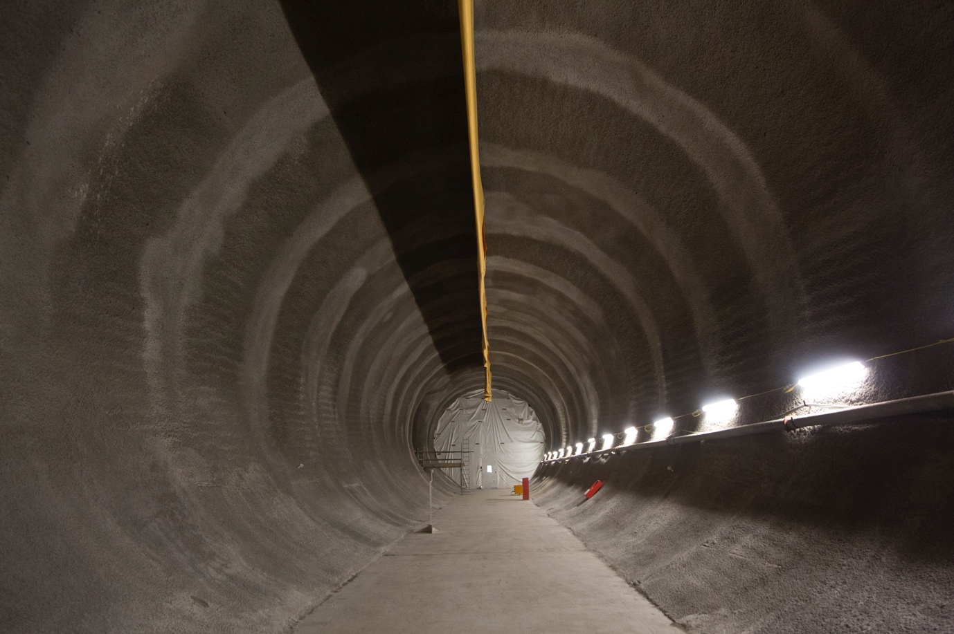
Figure 7 – Photograph showing uniform profile sprayed with state of the art spraying robot and bespoke survey software. References
[1] C.G. Bailey and G.A. Khoury (2011). Performance of Concrete Structures in Fire. The Concrete Centre.
[2] M. Cooke, R. Dimmock and A. Deane (2009). Fire Protection of SCL Tunnels — Best Practice Benchmarking. Crossrail Ltd. Unpublished.
[3] EFNARC (2006). Specification and Guidelines for Testing of Passive Fire Protection for Concrete Tunnel Linings.
[4] K.F. Garshol and C. Ziegler (2006). Computer Controlled Application of Shotcrete — A Status Report. Proc. Shotcrete for Underground Support X.
-
Authors

