Royal Woolwich Arsenal – Crossrail Box Sewer Diversion
Document
type: Technical Paper
Author:
Peter Buckley, ICE Publishing
Publication
Date: 03/11/2014
-
Read the full document
Introduction
Berkeley Homes (East Thames) Ltd. (BH) are providing The Secretary of State (The Department for Transport) with a Crossrail Station Box within the Royal Arsenal site at Woolwich. On completion, this will be handed to Crossrail Limited (CRL), the nominated undertaker under the Crossrail Act. Waterman Transport & Development Ltd (WTDL) are acting as lead consultant to Berkeley Homes (East Thames Ltd) for the civil and structural concept design.
The Station Box comprises a West End with minimum internal dimensions of 45 m by 26.6 m width, a Central Box of 173 m by 20.4 m width and an East End of 38m by 26.6 m width. It is planned to construct a station entrance at the West End with a single level structure above ground level and a 2-3 storey above-ground Oversite Development at the East End, but details have not yet been finalised. Over the Central Box and to the south of the West End and Central Box, Berkeley will be constructing a separate multi-storey Oversite Development. Arsenal Way will be reinstated in its current position between the Berkeley oversite development and the East End.
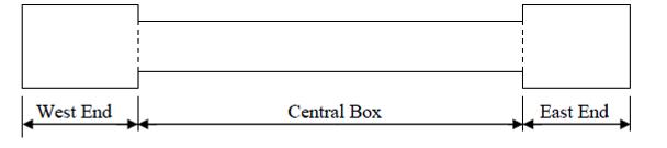
Figure 1. Station Box Components
As part of the Enabling Works, the existing sewers in Arsenal Way, Cornwallis Road and generally within the area of the proposed Station Box have been diverted through a new 1.2m diameter sewer on the north, east and south sides of the Station Box. The diverted sewer was installed in advance of the construction of the Station Box and Crossrail tunnels.
The new diverted 1.2 m diameter sewer was assessed for potential ground movements from the following activities:• Installation of the perimeter diaphragm wall
• De-watering of the station box to permit the safe excavation within the box
• Excavation within the station box and installation of quasi-permanent props
• Construction of base and roof slabs
• Release of de-watering
• Construction of the bored tunnels at either end of the station box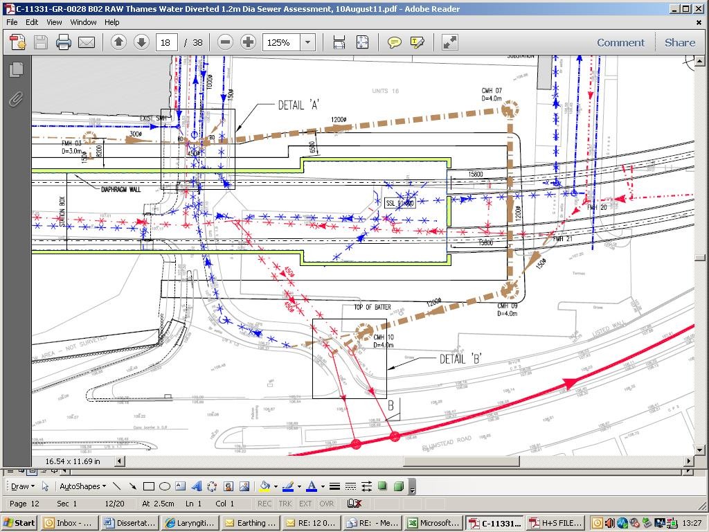
Figure 2. Diversion route from red alignment to brown alignment
Design Considerations
Ground Conditions
Crossrail undertook the initial site investigation using a company from their existing supply chain. Berkeley were requested to reduce the programme by 9 months for delivery of the Box to Crossrail. By Crossrail undertaking the site investigation (SI) using a company within their existing supply chain Berkeley did not have to undertake a tender and procurement process which contributed to the required programme reduction. The SI was extensive requiring trial pits, boreholes and ground water flow tests across the site. This SI was crucial for establishing local soil strata and site-specific soil permeability and parameters informing the design of the Box, the tunnelling and the service diversions.
The site is underlain predominantly by the Thanet Sand Formation overlying the Chalk Formation. Locally the Lambeth Group is also present (encountered in boreholes that are located about 100m from the station) and the River Terrace Gravels at the eastern side of the station. An alluvial channel runs through the west end of the Station Box in a south-west to north-east direction.
Figures 3 & 4 include the borehole interpretive drawing showing the representative geology beneath the site and the link in ground water level with the River Thames:
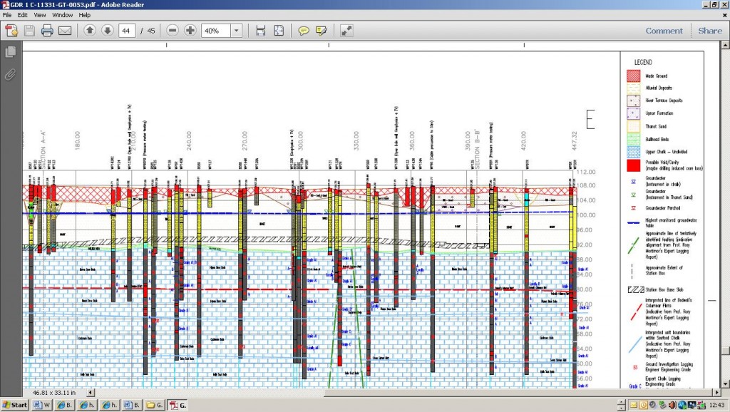
Figure 3. Interpretive Borehole Drawing
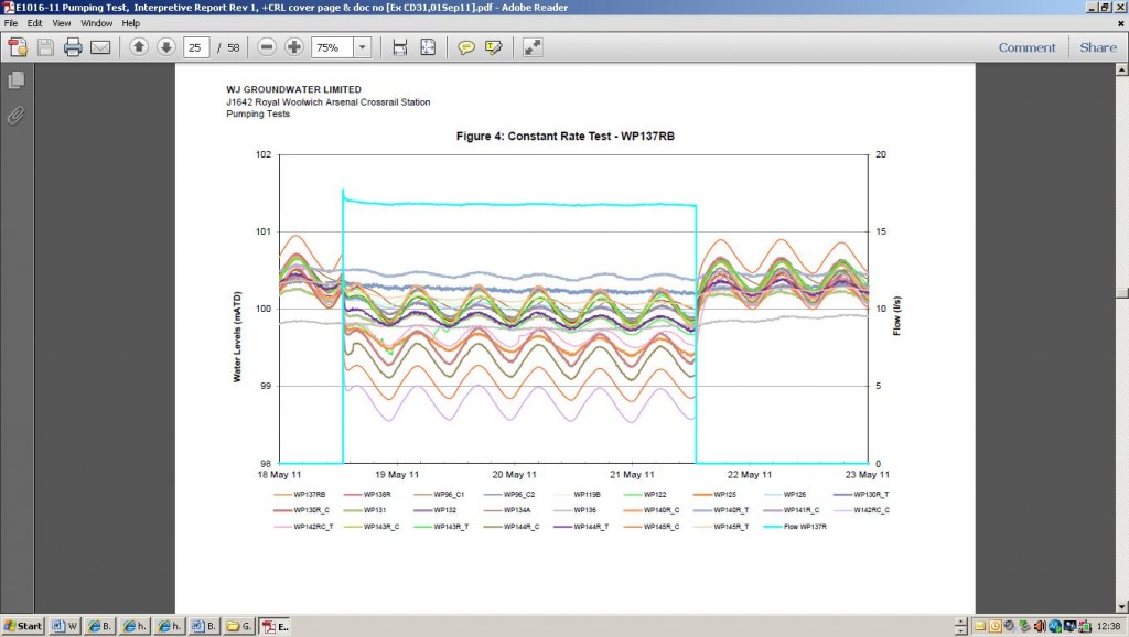
Figure 4. Constant Level Tests – shows the link with the tidal River Thames
Assessment Methodologies
Ground Movements
The estimates of ground movements due to the wall installation and construction of the Station Box have been based on measured movements for similar walls and excavations as given in the CIRIA guide C580 (reference 5.1). The graphs have been generated from previous project experiences with different types of retaining wall structures to draw correlations between diaphragm walls and the retained ground movement. They provide maximum movements for each type of wall construction and so would be expected to give a conservative estimate of actual ground movements at the Royal Arsenal Woolwich Station Box site.
Ground movements at or close to the corners of basements have been found to be 40-50% less than adjacent to long walls, i.e. plane strain conditions, due to the stiffening effect of the corner and the 3-dimensional effects of the end of the wall. The corner/end of wall effects have been assessed using the LUL Manual of Good Practice G-058 (reference 5.3). The ground movements at the diverted sewer location have been determined according to the ground level relative to the Station Box diaphragm wall toe level for the wall installation and maximum excavation level for the box construction. The ground movements also take account of the variable distance of the sewer to the face of the diaphragm wall. The calculated vertical, horizontal and axial movements have been summed for the installation and excavation effects at 2 metre intervals along the length of the sewer. Vertical settlement and horizontal movements have been combined to generate a resultant movement affecting the pipe. The calculated movements have been used to determine the flexural strains and joint rotations.
Assessment of Pipe Strains and Movements
The corner effects described above and the variation of the distance of the pipe from the diaphragm wall and level variations along its length result in differential movements of the pipe, which will cause rotation and pull-out of the pipe joints and possible flexural straining of the pipe.
The flexural strain resulting from differential movements is likely to be released by rotation of the pipe joints. However, theoretical flexural strains have also been assessed on the unlikely assumption of fully rigid pipe joints. The flexural strain has been estimated for the radius of a circular arc connecting every three consecutive displaced points along the pipe. The flexural strain, ε, is then calculated as ε = y/R, where y is the distance between the neutral axis and the outer face of the pipe and R is the flexural radius.
Axial strains may also occur near the Station Box corners due to the assumed elliptical shape of the horizontal movement strains, which would result in a horizontal movement component parallel to the wall.
The axial tensile strains have been combined with the flexural tensile strains. As the joints are able to displace longitudinally, the axial strain will be partly released through longitudinal movement within the joints.
Permissible Strain and Movement Limits
The diverted sewer is anticipated to be formed with 1200 mm diameter concrete pipes with steel bands over rubber or elastomeric flexible sealing inserts. The joints are required to allow rotation during the jacking operations to accommodate alignment adjustments. Rotation of up to 1 degree is permitted during jacking and, as the jacking forces are released, some residual rotation capacity will remain after installation of the pipe, which has been assumed to be 0.25 degrees. The longitudinal movement limit requirements are defined in BS 5911-1 and BS EN 1916 as 12.5 mm, but a more conservative limit of 7.5 mm has been assumed in line with CRL assessments elsewhere for Thames Water concrete pipes. The concrete strain limits are based on typical strain limits assumed for Thames Water concrete pipes and adjusted for possible locked-in jacking forces:
• Flexural strain in tension 120 x 10-6
• Flexural strain in compression 750 x 10-6
• Joint rotation 0.25 deg.
• Joint opening 7.5 mmAssessment Results & Conclusions
The ground movements and strains at 2 metre intervals along the length of the diverted sewer were analysed.
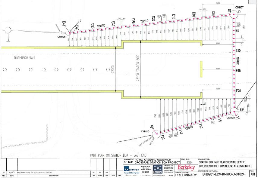
Figure 5. Settlement analysis reference points
The maximum rotation of the joints, assuming no flexural restraint of the pipe, has been estimated as 0.15 degrees, which is well within the rotation capacity of the joint.
The maximum combined theoretical flexural and axial strain in the pipe is generally less than the permissible strain (120 x 10-6). The strain limit is exceeded slightly at one location near point D5, where the strain has been estimated as approximately 130 x 10-6, but this is believed to be due to the approximate numerical procedures and not considered likely to occur in practice. The strains in the pipe are therefore believed to be acceptable.
The maximum pull-out movement at the joints occurring near the Station Box corner is estimated as 5.3 mm, which again is within the capacity of the pipe joint.

Figure 6. Settlement Calculations Summary
The diverted sewer is therefore considered to be able to accommodate the anticipated ground movements occurring as a result of the diaphragm wall installation and excavations for the construction of the Station Box.
The effects of the tunnel construction, particularly under the diverted sewer section running directly over the tunnel alignment, will be assessed separately by Crossrail. The assessment by Crossrail will incorporate the effects of both the Station Box and tunnel construction.
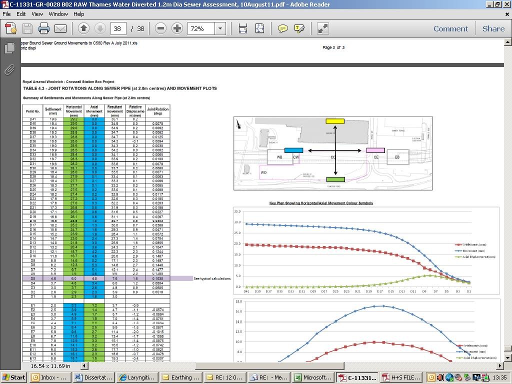
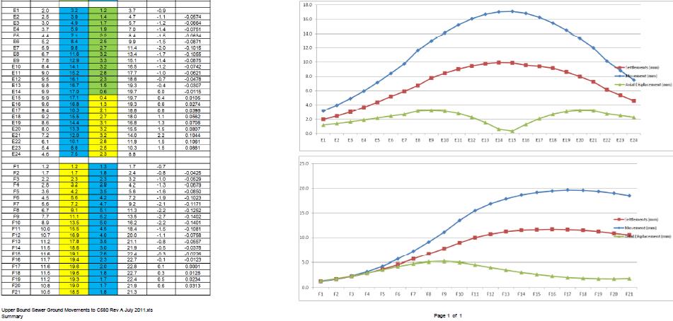
Figure 7. Upper Bound Sewer Ground Movements
Construction
The Contractor
The works package was awarded following competitive tender to Joseph Gallagher who entered into Berkeley’s standard form of contract. The methodologies Gallagher were to use were in line with the design proposals of a trenchless solution using a tunnel boring machine and pipe jacked solution.
Construction Method
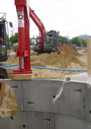
The works required the sinking of four caisson shafts up to 10 m in depth; two were 5 m in diameter and one was 3.66 m diameter. These were sunk below the water table which made localised dewatering necessary until the mass concrete base was cast. The caissons acted as launch or reception chambers for the tunnel boring machines (TBMs) and also served as the final manhole chambers. Below is a selection of photos showing the construction process:
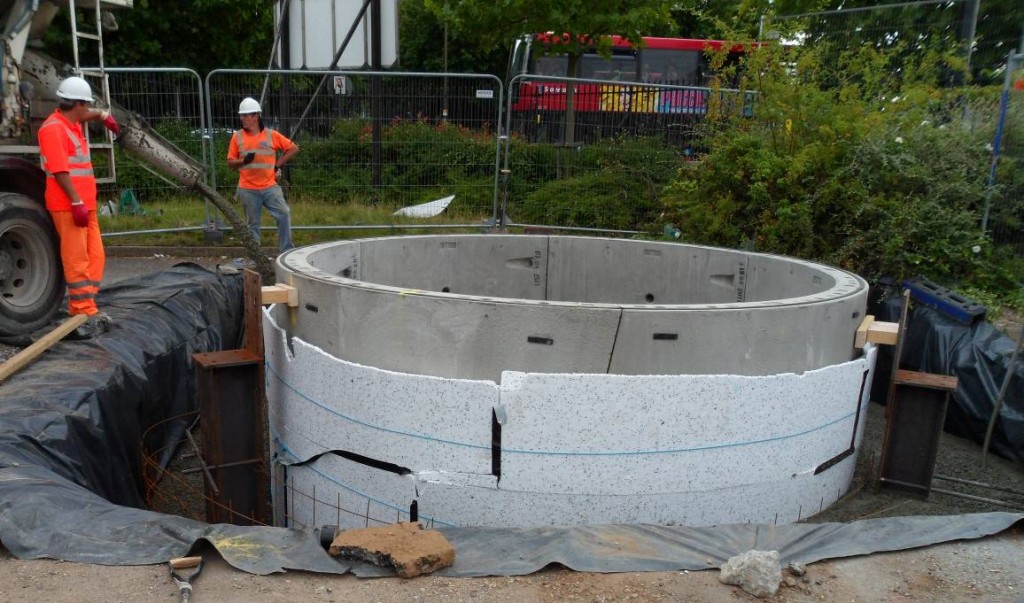
Figure 8. Stage 1 – Installation of cutting rings and jacking collar
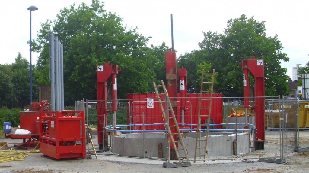
Figure 9. Jacking rigs installed
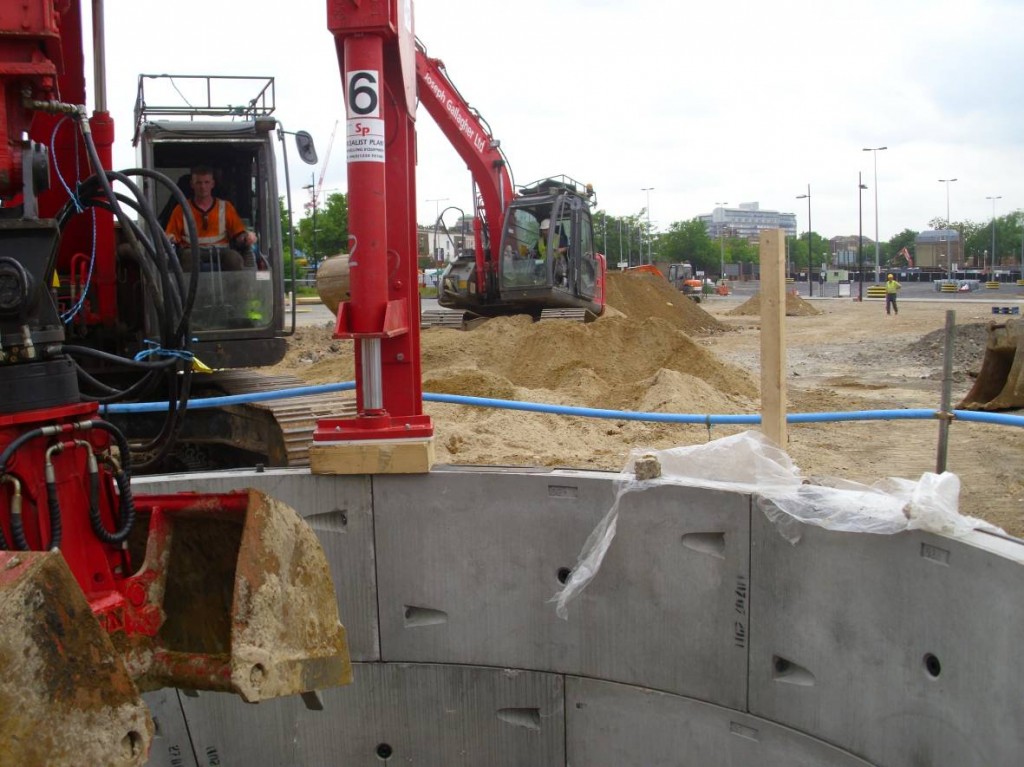
Figure 10. Jacking caisson into the ground as the excavation within progresses
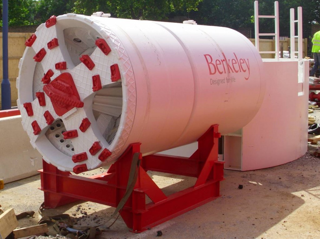
Figure 11. Tunnel boring machine (TBM)
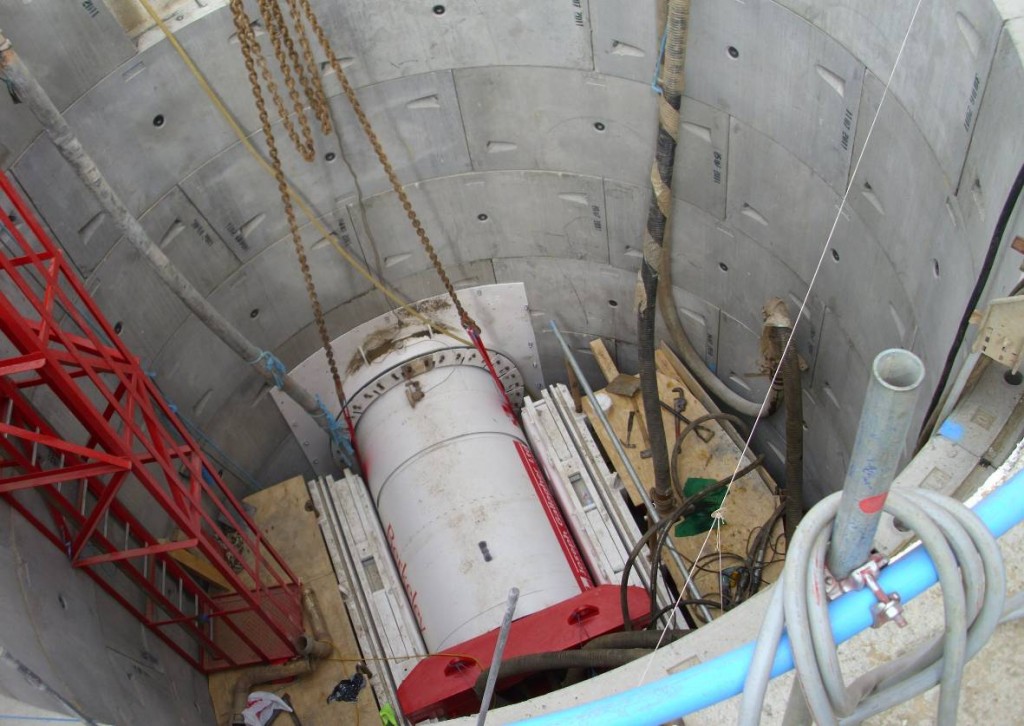
Figure 12. Launching the TBM
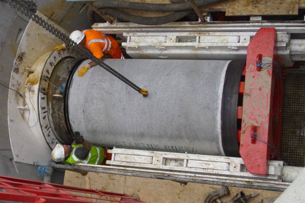
Figure 13. Pipe jacking behind the TBM
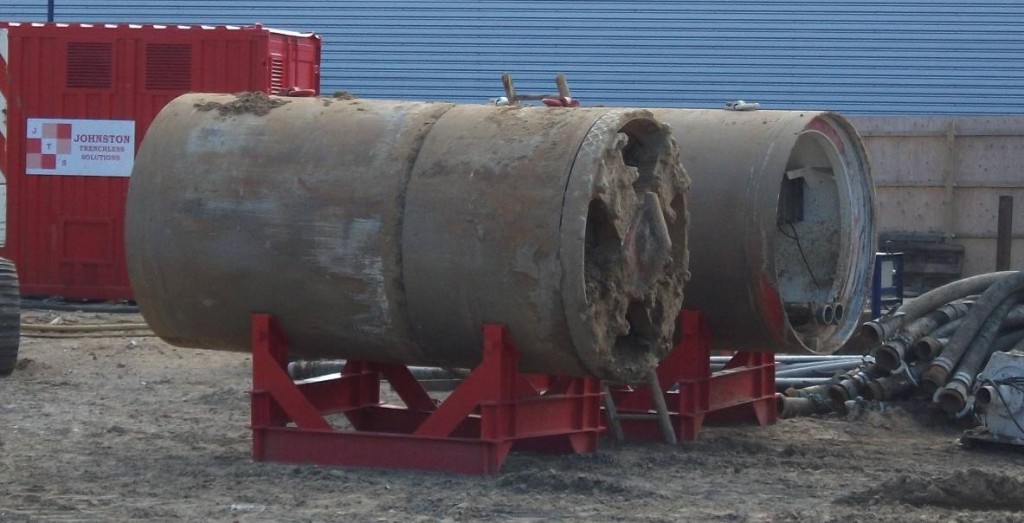
Figure 14. TBMs recovered
Construction Challenges & Conclusions
Generally there were very few unforeseen events during construction. The employment of a specialist contractor such as Joseph Gallagher Ltd ensured that risks were identified and mitigating measures put in place in advance of the works to safeguard the delivery of the works and the programme.
A small quantity of white asbestos was uncovered which required specialist contractor removal. The area was surveyed to ensure no asbestos remained so that works could continue.
Dewatering systems were in place to cope with any significant influxes of water into the caissons however only minimal water ingresses were experienced.
Overpumping of the flows through the existing pipework was installed to facilitate the new pipework installation. This was in place throughout the works and Berkeley have facilitated a further four week overpumping operation for the period of the TBM passing beneath the diverted route. This is to provide resilience to the Royal Arsenal estate sewage outfall in case any significant deflections occur whilst tunnelling.
The emergency services attended site to familiarise themselves with the site and what scenarios they may be faced with. The works were completed without incident, accident or injury.
Berkeley continues to work closely with Thames Water, Crossrail and their tunnelling contractor HMJV to mitigate any impacts that the tunnelling operation may have on this key element of infrastructure.Acknowledgements
Grateful acknowledgement is made to the following companies for their contribution to the project and to this report:
Crossrail Geotechnical Team
Berkeley Project Management Team
Waterman Group Design Team
Joseph Gallagher & Sons Construction Team & their specialist business unit Johnston Trenchless Solutions
Iseki Tunnel Boring Machines
Thames Water
References
1: CIRIA C580, 2003, ‘Embedded retaining walls – guidance for economic design’.
2: CRL Document No. CR-STD-303-7, Version 5.0, August 2009, Civil Engineering Design
Standard, Ground Movement Prediction.3: London Underground Manual of Good Practice G-058.
4: Crossrail Information Paper D-12 – Ground Settlement, Version 5, February 2008.
5: WTDL document no. C-11331-GR-0001-C01, Royal Woolwich Arsenal Civil and Structural Concept Design Statement, April 2011.
-
Authors

