Sprayed Concrete Lining Falls and Exclusion Zone Management
Document
type: Technical Paper
Author:
Mike King BSc CEng MICE, Adrian St.John, BEng (Hons) Eur Ing FICE CEng, David Brown, John Comins BEng HND ACSM, ICE Publishing
Publication
Date: 31/08/2016
-
Read the full document
Introduction
Like most major urban centres, London is faced with an ever increasing population and the need to transport people to their places of employment and entertainment. The Crossrail project provides an East-West link from the suburbs to the city enabling an additional 200 million journeys each year linking up major business centres and existing transportation interchanges, while reducing congestion at street level and within the current over-used underground system.
In the central section of the project, in addition to over 42km of precast concrete lined bored tunnels the project has constructed major structures in Sprayed Concrete Linings (SCL), including 5 new stations, 6 crossover caverns and numerous passages, adits and ventilation tunnels. The construction of these structures has taken approximately 4 years, and has involved the spraying of over 200,000m3 of concrete, a small proportion of which fell from its designated location when applied. The safety implications of falls of SCL was a major concern from the start of the project, but it was evident that a complete lack of available records from previous projects hindered risk assessments or the ability to make meaningful comparisons concerning spraying or material performance. This paper therefore attempts to redress this lack of data by providing information on the falls experienced on this project, allowing frequency and volumes of falls to be judged, and providing guidance on the efforts made by the project to reduce falls further even though exclusion zones to high risk areas were imposed.
Construction Methods
Table 1 below summarises the main contracts which contain elements of permanent works SCL tunnels, noting that the listed total primary lining lengths include pilot tunnels, side drift tunnels and enlargements as separate tunnels for the purposes of this paper. All completed tunnels were approximately circular or elliptical.
Contract No. Principal Contractors Total Sprayed length (km) Excavation sizes (m) Primary lining Secondary lining From To C300/C410 BAM / Ferrovial / Kier 4.8 2.2 4.4 x 4.6 11.8 x 14.9 C305 Dragados / Sisk 0.6 0.4 8.6 x 8.0 13.5 x 16.6 C360 Costain / Skanska 0.3 0 4.9 x 5.2 7.9 x 9.0 C435 BAM / Ferrovial / Kier 2.3 0.4 6.9 x 6.1 10.3 x 11.1 C510 Balfour Beatty / Morgan Sindall / Vinci 8.6 2.9 4.3 x 3.6 13.7 x 17.3 Table 1 – Contract breakdowns and sizes
Given the vast range of tunnel sizes required by the project, it was inevitable that there would be a range of construction sequences used in order to deal with the design requirements, geometry, and the ground and ground water conditions. The following points briefly summarise the lining build up by layers, with typical design minimum dimensions provided for a Platform sized tunnel (approximately 9m internal diameter), excluding any tolerance allowances:
- Initial / Sealing layer (75mm)
- Primary Lining – part of the permanent support (300mm)
- Regulating layer (40mm)
- Waterproof membrane (Sprayed membrane, 3-6mm)
- Secondary lining (250mm)
- Fire protection layer – structurally part of lining (50mm)
Some lining layers were themselves sprayed in more than 1 layer to allow for inclusion of reinforcement or to avoid a too aggressive build-up of thickness.
The construction sequence advances employed to create the linings included:
- Full face
- Top heading, bench and invert with near vertical or sloping faces
- Pilot (segmental lining or SCL) with enlargement with horizontal face division
- Single side drift and enlargements with horizontal face division in both faces
- Double side drift and enlargements with horizontal face division in all faces
The records discussed in this paper include data from all of the above.
Definition of the issue and data collection
In its simplest form, the definition of a “fall” is:
“The release and fall of a mass of material from its at rest position.”
However, when considering the sprayed concrete tunnelling work environment, there are a number of different events that can sit within this general definition, namely:
- A fall from the tunnel crown or shoulders or face of a mass of sprayed concrete during, or after spraying is complete.
- A fall of ground from the tunnel crown or shoulders or face during the excavation sequence.
- Slumping of sprayed concrete from the tunnel shoulder or axis during, or after spraying is complete.
- Slumping of sprayed concrete from headwalls during or after spraying is complete.
- Slumping of concrete after spraying thereby leaving a void between layers.
Even very small fallouts (for example 0.5m x 0.5m x 0.1m) would weigh 60kg, so all of the above therefore have the potential to cause harm and pose a hazard within the tunnel environment. It is also important to remember that falls can occur at any time during the excavation or concrete curing phase and at any stage within the construction sequence. Modern sprayed concrete tunnel designs often include multiple layers and falls can occur from any individual concrete layer.
It is also worth noting that each layer will probably be sprayed with a different concrete mix, i.e. with or without steel or polypropylene fibres or with a reduced/increased accelerator dosage. There are therefore multiple potential reasons for a fall even just considering these few variables. A full record of the data gathered during the Crossrail project will be made available via the Crossrail Learning Legacy and a summary of the key analysis of the data is provided later in this paper.
Therefore, in consideration of these many and varied possibilities, the definition of a fall can be revised to:
“The uncontrolled release and movement to ground of a mass of material from its at rest position.”
In order to fully understand the mechanism and root cause of a fall, a comprehensive reporting system is fundamental. At Crossrail, safety management software provided by RIVO was used to collect and collate all health and safety incident data. In its original format, this system did not record sufficient information to enable a meaningful root cause analysis of SCL falls and therefore a standard reporting classification was introduced to generate consistency across the wider project.
In addition, and in recognition of the shortfall in the quantity and quality of data being gathered through the RIVO system, individual contracts developed their own bespoke systems, based upon an agreed minimum level of data capture, for gathering more comprehensive data. Table 3 contains a summary of those parameters recorded and, based on the experience from Crossrail, the additional parameters which should be recorded in the future. Experience gained over the duration of the Crossrail project has resulted in the publication of a “Good Practice Guide” for the management of exclusion zones in SCL works [2]. Further general guidance can be found in a number of industry documents, although none deals specifically with management of exclusion zones and the risks from falling shotcrete [3] [4] [5] [6] [7] [8] [9] [10] [11].
Incidents and Risks
The ranking in relation to the frequency of occurrence of falls observed is as follows, with most frequent occurrences observed listed first.
- A patch of concrete from the first layer of the primary lining falling from the tunnel crown from a position between 10 o’clock and 2 o’clock.
- Slumps of concrete from the face after spraying.
- Falls of ground (greasy backs) from either the crown or face where near vertical faces were used.
The following incidents also occurred although at a much reduced frequency:
- A fall of concrete from the initial sealing layer typically from a position in the crown between 10 o’clock and 2 o’clock.
- A fall of concrete from the second layer of the primary lining typically from a position in the crown between 10 o’clock and 2 o’clock.
- A fall of concrete from a thickening layer typically from a position in the crown between 10 o’clock and 2 o’clock.
- Falls due to impact from plant. These incidents should perhaps be more properly termed “knock-outs”.
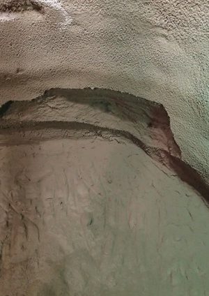
Photos of typical fallouts are shown in Figures 1 and 2.
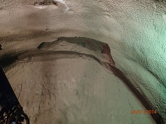
Figure 1 – C510, Whitechapel Eastbound Running Tunnel West Pilot 2.0m x 1.0m x 0.15m Primary 1 layer 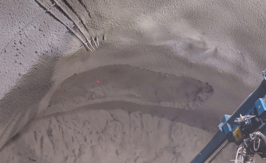
Figure 2 – C510, Whitechapel Cross Passage 3, 2.5m x 1.0m x 0.2m Thickening layer An analysis of the data has identified one key safety critical period – immediately after spraying and whilst the concrete is gaining early strength. An evaluation of the data relating to the timing of falls demonstrates that the vast majority of incidents occur within 15 minutes of completion of spraying. A significantly lower number of falls occur between 15 and 30 minutes after spraying.
The most effective method for addressing this risk is by the creation of an exclusion zone within the work area during each advance of the face. Although this varied slightly from site to site, the operational parameters used to define and control the exclusion zone were typically 30-45minutes (minimum) and 0.5MPa (minimum). However, the principle remained consistent across all sites, to keep personnel away from freshly sprayed concrete during the period of early strength gain.
The risk to personnel working at the face needs to be carefully considered when establishing exclusion zones with a particular emphasis on the type of work being undertaken. Logic and common sense need to be applied but a simple set of rules is the prime objective taking into account who needs to access specific areas, when and why. The safety of the workforce is always the primary objective but excluding everyone at all times is clearly not practical. Each stage of the construction process needs to be risk assessed with the intention of reaching a balanced solution ensuring that both the operational and assurance needs of the project are being met.
For different layers within a typical SCL tunnel the hazard remains the same, however the likelihood of a fall does vary with the different stages of construction, and Table 2 provides an outline summary of contributory factors.
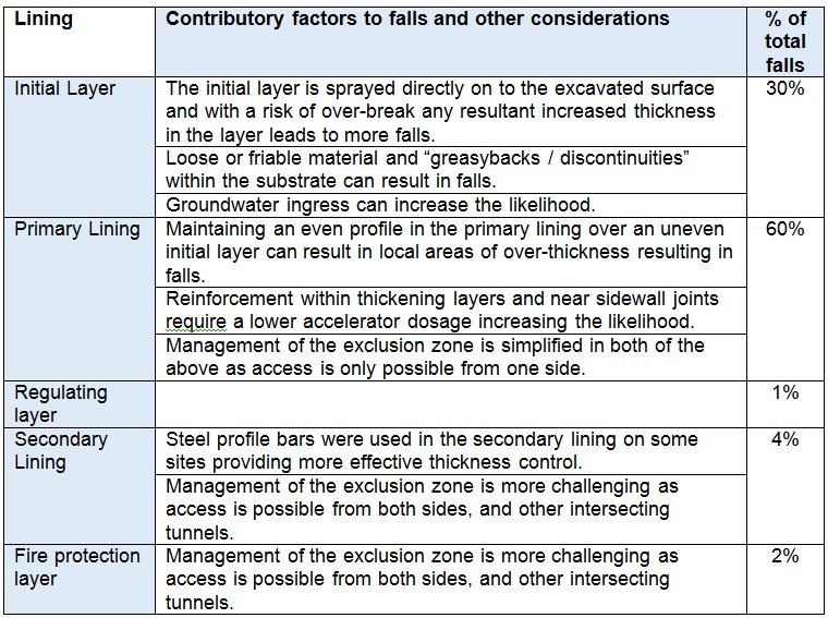
Table 2 – Factors affecting fall potential by layer Discussion and observations on data recovered
Pertinent data following a fallout was manually collated and entered into a spreadsheet. The data was scrutinised in considerable detail by the site teams in an effort to gain a better insight into root cause and contributory factors. Some contractors developed self-populating dashboard reports which highlighted useful key performance indicators or to highlight other relevant trends. Example graphics are provided in Figure 3, and a narrative on the key Crossrail-wide observations is offered below.
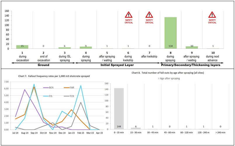
Figure 3 – Example outputs from dashboard reporting There were no reported “safety critical” incidents (e.g. fallouts occurring after the exclusion zone had been lifted). There were two “knock outs” where plant impact caused young shotcrete to fall circa 2 hours after spraying was complete (see Figure 3). There was one instance where a fallout occurred circa 2 hours after spraying had been completed. However, rigorous testing for Early Age Strength (EAS) was indicating that the shotcrete was not gaining strength; the exclusion zone therefore remained in force, and the tests were repeated until, eventually, the shotcrete fell. This is just one of many documented examples of rigour and good practice being followed by the site teams.
No correlation was found on the following parameters: day of the week, weekday / weekend, accelerator dosage, flow rate, shotcrete temperature, ambient temperature, undrained shear strength of the soil (Cu), early age strength or in-tunnel convergence.
Some correlation was witnessed at certain sites for the following parameters: hour of day, shift (day shift, back shift or night shift), but this was not a universal trend.
A strong correlation was witnessed for the following parameters: challenging geometry, particularly where combined with reinforcement congestion in a sidewall drift (this required the accelerator dosage to be lowered to achieve encapsulation, resulting in numerous successive fallouts).
The vast majority of fallouts occurred either during spraying or within 15 minutes of the completion of spraying. Most fallouts occurred in the primary lining, and there were a considerable number attributed to challenging geology, particularly at the more easterly Crossrail sites (see Figure 4).
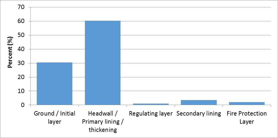
Figure 4 – Percentage fallouts by layer The sizes of fallout varied greatly from 0.02m3 to 8m3, with a median of 0.3m3. 25% of the falls were between 0.61m3 and 5m3, see Figure 5 for distribution. The majority of the falls were between 30 and 60 degrees wide (around the arc of the tunnel).
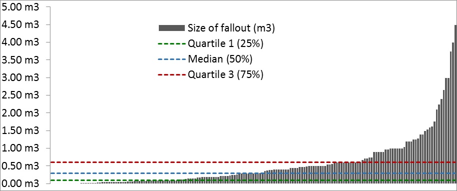
Figure 5 – Distribution of shotcrete fallout sizes Differences across sites observed
Normalised results (incident rate per 1000m3 of shotcrete sprayed) across all the Crossrail sites are shown in Figure 6.
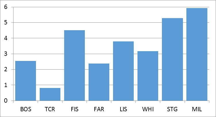
Figure 6 – Comparison across all Crossrail SCL sites of long average fallout rate (per 1000m3 shotcrete sprayed) Detailed information regarding root cause analysis was not available for all fallout incidents, and even when it was, the list of possible “root causes” was not consistent across all sites for the full construction duration. A thorough review of the available data has led to the production of Figure 7 below, which illustrates a summary of root causes.
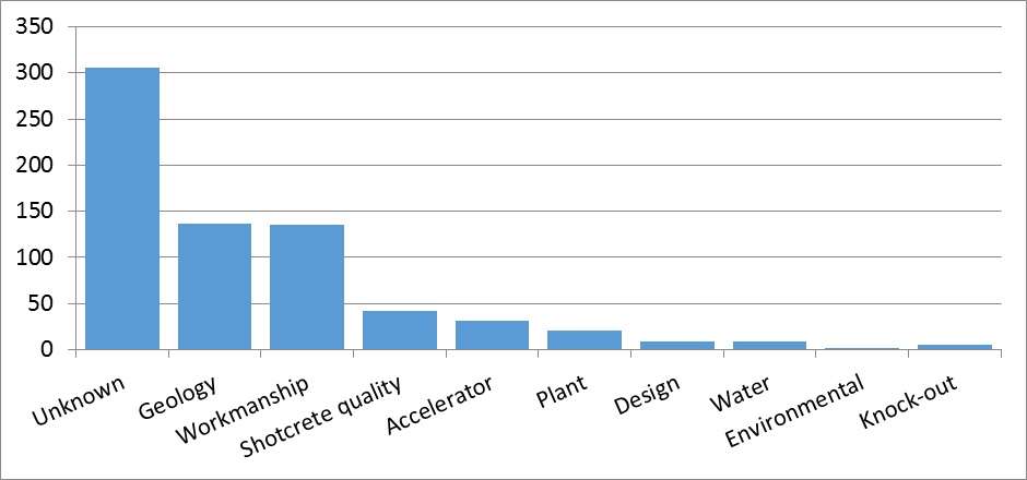
Figure 7 – fallout analysis by root cause (amalgamated statistics) The following should be noted in regard to Figure 7:
- Geology – includes attributed cause to ground conditions, obstructions
- Workmanship – includes over-excavation, building up of layers too quickly, spray rate too high
- Shotcrete quality – generic problems with quality / consistency, or inadequate early age strength
- Design – usually reinforcement congestion or geometry
- Environmental – usually cold weather
- Knock out – due to plant impact
Conclusions in respect of the data and data capture
There are six key points to be concluded from the review of the data and data gathering on Crossrail.
- The use of self-populating “dashboard” reports are considered to be helpful in readily identifying trends without excessive administrative effort. These are considered to be “best practice” in SCL works.
- Recording methods need to be consistent across all sites for effective assessment, and the quality of recorded data can potentially be subjective, prone to human error and variable. Generally, consistency was achieved on Crossrail, but small variations still remained between the various worksites. This has made it difficult to effectively compare performance between sites, or to amalgamate all the data into a single database or spreadsheet.
- The manual collection of raw data has led to significant gaps in the datasets, which has greatly hindered the ability to use statistical methods to scrutinise the data in more detail and establish clear links between cause and effect. This was particularly difficult given the number of concurrent and interrelated variables.
- The absence of adequate and reliable data from the spraying robots has largely prevented the “normalisation” of the data. This has made it virtually impossible to isolate individual factors to assist in root cause analysis. As a result, there may be trends in the data sets which are not yet apparent.
- There was a considerable amount of “good practice” evident on site, yet a significant number of fallouts still occurred, many of which appeared to have no clear cause. On this basis, there is considerable scope for improvement across the industry, to better understand this phenomenon and reduce future occurrences.
- It is vital to feedback details to the workforce once the likely cause of a fall is known, although it is recognized that the root cause is not always easy to identify. “Lessons learned” briefings should be given to both the gang involved at the time and other gangs working on similar activities, to promote understanding and continuous improvement, even if different contractors are undertaking the works.
In respect of items 3-5, there is a clear need to automate the collection of raw data from the spraying robots in a consistent, robust and transparent manner. Increasing levels of automation and sophistication of shotcrete spraying plant should be able to record and provide most of the relevant data automatically, whether a fallout has occurred or not. Gathering a complete continuous suite of data will permit rigorous statistical analysis of the data and will enable normalisation of the data for easy comparison, with a corresponding reduction in dependency on human intervention and data loss. For example, no meaningful evaluation has been possible to date for “fallout rate plotted against spraying rate (m3/hour)” or “fallout rate plotted against accelerator dosage (%)”, since we do not yet possess that level of continuous data for every single m3 of shotcrete sprayed. Instead, all we have is a snapshot of those parameters manually recorded when the fallout occurred.
The spraying robots should be configured for continuous data capture of all fixed and variable parameters, and this data should be securely stored on board the spraying plant and extracted either manually (via a USB stick) or automatically (via an underground Wi-Fi network) in a suitable format (e.g. .xls or .csv). The aspiration for the SCL industry should be to achieve the levels of telemetry and data capture which now exist for modern TBMs, so that this data is readily available to site management. The use of a Wi-Fi network has numerous wider potential benefits.
Parameter Crossrail Aspiration for future projects Date and time (24 hr clock, from which shift can be ascertained) Manual Automated Fallout type (1-10) and reference based on standard RIVO criteria Manual Manual Site and Tunnel name, reference location, advance number Manual Automated Type of tunnel (full face, top heading/bench/invert, sidewall drift, etc.) Manual Automated Nozzleman ID Manual Automated Pump rate Manual Automated Layer (initial sealing layer, primary lining, regulating layer etc.) Manual Automated Description of fallout including dimensions and mass Manual Manual Actions taken after fallout Manual Manual Root cause (if known) Manual Manual Time of fallout after spraying completed and test panel sprayed Manual Manual Shotcrete age after batching Manual Manual Location of fallout in relation to clock face position Manual Manual Shotcrete details including workability, accelerator dosage (%), spraying rate, shotcrete volume sprayed, temperature, compressed air usage Manual Automated, continuous Ambient temperature Manual Automated Spraying robot manufacturer, model / specification and serial number x Automated Accelerator batch ID (traceability) x Barcode Shotcrete batch ID (traceability) x Barcode Table 3 – Critical parameters for measurement (actual and aspirational)
Discussion on Root Causes of Fallouts
The full reasons for SCL fallouts are not well understood, partly because we cannot as yet compare data from when a fallout occurs with data where a fall did not occur. However the root causes of fallouts are numerous and normally would involve a combination of a failed series of factors, some of which could be human, material or equipment related. The table below lists some groups of possible causes or influencing factors to loss in spraying performance that could increase the likelihood of fallouts, in isolation or in combination with other factors.
When most of the above factors affecting the performance and workmanship of sprayed concrete are controlled and combined effectively then the propensity of fallouts can be minimised.
PLANT Poor spraying plant selection Consider tunnels’ size, lining layer thickness, geometry, length, gradient and access. Over-reaching of arm could inhibit even coverage due to excessive nozzle stand-off, poor operator visibility or control, and areas of over-sprayed layers. Additive mono-pumps deliver more consistent supply of accelerator to shotcrete stream mixer at nozzle than peristaltic equivalent.
Pulsation effects have been witnessed during changeover between pistons, causing bands of over-accelerated shotcrete (the accelerator supply is constant, but the concrete is delivered in pulses, with a delay in delivery during piston changeover).
Currently a wide range of plant is available from manufacturers such as Jacon, Meyco, Normet and Putzmeister
Poor excavator & bucket selection Poor control leading to over-excavation, damage to adjacent freshly sprayed layers. Older SCL equipment and/or poor plant maintenance Modern / new SCL plant typically performs better, particularly when combined with planned preventative maintenance. Cleanliness of spraying plant (hoppers, piston bores, accelerator pumps, valves, lines, mixer (“turbo”) at nozzle). PLC control boards can malfunction whilst appearing to be fully operational. Pulsation effects more noticeable in poorly maintained plant. Calibration of accelerator dosage pumps, in particular, should be checked and re-calibrated after a fallout. Poor batching or remixing (on site or off site) Batchers – aggregate contamination, mixing pan cleanliness, batch mixing sequence and time to suit constituents and additives. Offsite batching and delayed supply to site by remixer could increase the potential for water overdosing, segregation and diminished quality control during intensive periods of work. Loss of temperature control of mix in extreme weather conditions.
Static or mobile remixers – poor cleanliness could inhibit adequate mixing of constituents.
Concrete batch performance and consistency. Particular differences in performance have been witnessed between off-site batching, on-site batching and pre-bagged emergency SCL supplies
Poor compressed air delivery Pulsing or fluctuations in delivery of compressed air can result in concentrated bursts of accelerator during piston changeover followed by a stream of un-accelerated or over-accelerated shotcrete. Plant overhaul and changes to PLC can improve this effect. On-board compressors can be replaced with larger fixed units in conjunction with large air receivers providing a greater degree of redundant capacity, enhancing performance when spraying large volumes. However, this can lead to too much compressed air being delivered, resulting in a dusty atmosphere.
Plant maintenance and air quality important factor in shotcrete performance.
GEOLOGY Unfavourable Geology Affects the initial lining only. Greasy backs and other closely fractured blocks of clay can cause fallouts of initial layer. Drained sand lenses in the face led to ravelling when initial layer applied.
For large faces in top heading, the initial layer was thickened and sprayed in two passes. This was typically stipulated in RESS and/or decided on site by SCL staff.
Groundwater seepage from crown or face Damp or wet fractures particularly in crown can lead to loose substrate which, when sprayed, create a weak layer onto which the thick heavy primary lining is applied. Water can also seep through primary layers in crown creating weaker layers in fresh concrete. SHOTCRETE AND COMPRESSED AIR DELIVERY RATES High spray rates (18 to 24m3/hr) Whilst suitable for bulk filling large invert rounds, high spray rates in crown are likely to result in fallouts (fresh concrete has not developed adequate strength before next layer is applied). Operator skill, plant and materials performance need to be to a very high standard when spraying at such rates. Factors such as tunnel geometry, lining thickness, area and position all need to be considered when determining optimal spray rate for a particular round. Compressed air volumes A key factor in carrying and spreading concrete onto substrate. Linked to choice of plant. Considered that optimum air volume for large spray robots in the range 375 to 425cfm Compressed air pressure Air pressure should be consistent with the equipment used and should not fluctuate during spraying. ACCELERATOR TYPE AND DOSAGE Accelerator dosage and type Trials essential since performance (and required dosage) varies from product to product. Slow initial set ideal for spraying around reinforcement. Range 3.0% – 10.0%, but typically 7% to 8%. Higher dosage used during trials, in temporary works or when cement quality drops. Dosage reduced for spraying below axis and/or around steel bar reinforcement.
Careful storage important (temperature, rotation and agitation).
Faults with dosing system PLC or pump faults can lead to reduced dosing for a given cement volume. Regular checks on dosage and plant calibration should be standard practice. LAYER THICKNESS, PROFILE CONTROL, OVER-BREAK AND SUBSTRATE PREPARATION Single thick layer One of the highest risks of fallout occurs when operators spray too much in one area in one pass (possible link with production bonus). Suggest maximum 250mm thick single layer (subject to site trials) – built up with multiple passes of 40 to 75mm each to avoid “bulk filling”. Consider limiting via RESS or introducing hold/wait points or spraying additional test panels when spraying large volumes. Substrate material, surface preparation Cleanliness of substrate, consistency of geometry (profiling) for excavation and previous shotcrete profile. Reliant on nozzleman to apply individual passes at correct thickness. Substrate cleanliness can be affected by the work environment (including forced ventilation and prevalence of dust). Overbreak and over-excavation Excavation accuracy (particularly overbreak). Tendency to create thick areas in a single pass when filling in over-break during spraying of initial layer. Need to fill in stages, allowing time for strength development, particularly in crown. TUNNEL DESIGN, GEOMETRY AND LAYOUT Tunnel design, geometry and layout Principal geometric issue are “large flat crowns” e.g. in crossover caverns with single/double side drifts. Wide thick crown increases likelihood of fallout. Complex shapes at junctions between platform tunnels and cross passages means the design excavated profiles are not always possible resulting in uneven layer thickness. Significant bulking required in crown in some designs (up to 1.5m).
Some tight corners (e.g. top of side drift tunnels) or angles cannot be excavated and sprayed easily with robot due to reduced nozzle standoff distances, operator’s visibility. Can be prone to poor compaction. Should be limited by design & method.
Changes in geometry Allowance should be given to the learning curve of the excavator operator and nozzleman during significant changes in tunnel geometry and lining thickness. Headwalls One incidence of 8m3 fallout from a headwall. Risk assessment should specifically consider large volumes of continuously-sprayed shotcrete and consider suitable controls (e.g. additional hold points, additional trial panels). Permanent SCL Design Designers should minimise risk of exposure to fallouts by reducing need for manual work at or near the face e.g. placement of Kwikastrip, lattice girders. Mechanised working at safe distance should be maximised and manual work removed. Temporary SCL Design Should consider joint geometry and position, height of bench and depth of invert relative to work platform in order to reduce exposure to large faces. Stepped or sloping face could help to reduce fallout hazard.
Larger volumes applied during secondary lining spraying over larger areas increase risk.
REINFORCEMENT DIAMETER AND CONGESTION Influence of steel rebar Steel bar reinforcement congestion can lead to compaction and shadowing problems. Low accelerator required for heavily reinforced areas. This can result in slumping in crown. Steel bars should be stiffly fixed to avoid their vibration or shaking during spraying and subsequent loosening of freshly sprayed areas. Encapsulation of reinforcement always an issue with heavily reinforced areas. Max recommended single 20mm bar per layer. WORKMANSHIP, TRAINING AND EXPERIENCE Workman-ship, training and experience Skilled experienced nozzleman trained to EFNARC certification scheme including 3-5 years’ experience across a wide range of tunnel sizes, spraying plant and shotcrete materials. Particular skill and understanding is required in relation to variable spraying parameters (spraying too much shotcrete / too thick in one area / spraying rate too fast). Training and competence Familiarisation training on all plant should be arranged on site during early stages of construction. New nozzlemen should be chaperoned initially and assessed by competent person. Training should be also given for associated functions including engineers, pump men, re-mixer and batch plant operators. SHOTCRETE MIX AND CONSTITUENT MATERIALS Variability in constituent materials of a shotcrete mix (raw materials supply) Risk of fallouts increases when quality and blend of materials drops, even when certificates of conformity are provided, ie material may still be compliant with Standards. Factors affecting performance of sprayed concrete include cement grading, cement replacements, gypsum content, aggregate grading, moisture content, water temperature, chemistry and presence of contaminants, all of which vary slightly over time.
Fibres in shotcrete mix Polyfibres can affect early strength gain and workability. Steel fibres can affect flow of sprayed concrete around steel bars. Shotcrete mix additives Variations in quality of Microsilica , plasticisers, air entrainers, and retarders can all affect sprayed concrete performance. Accurate control of dosage, age, workability, storage and agitation are all considered fundamental Shotcrete temperature Temperature of fresh delivered concrete should be regulated within the range 15 to 17°C. The performance of some accelerators is more sensitive than others to variations in temperature. Particular difficulties encountered with early age strength during cold weather Exclusion zones
The use of exclusion zones has already been mentioned in this paper. To ensure a uniform approach across the project, for several reasons including a recognised system for people moving between contracts, the Contractors, Designers and Client produced a guidance document that was implemented on all sites. The “Best Practice Guide – SCL Exclusion Zone Management” document has been made available through https://www.britishtunnelling.org.uk for reference. The guidance is applicable for initial, primary and all subsequent sprayed layers, and the basic principles of the system adopted on the project are noted below:
- Terms for the different exclusion and restricted zones are defined for consistency and sites should keep pictorial details of the zones close to access points to these zones at all times.
- An exclusion zone always means no personnel access for any reason. Requires rigorous enforcement.
- Roles and responsibilities, particularly for testing and release of zones, are assigned and limited to those who are not distracted by other activities.
- Minimum requirements for exclusion zone release and restricted areas are defined including minimum distances, minimum concrete strengths, time limits, physical barrier requirements and personnel limits in restricted areas.
- A control process is set out including the procedure for releasing an exclusion zone or restricted area.
- Information has been provided concerning the communication of the exclusion zone management process and there are other measures noted which might be considered including the use of CCTV monitoring systems, which were used on Crossrail sites.
The document provides guidance on sensible precautions and approaches to take but it is only through the diligent application by all personnel underground of the principles detailed that the system can ensure continued safety at the face.
Conclusions
There are a number of conclusions reached throughout this paper that relate to issues associated with minimizing the likelihood of a fall of material, and ensuring that relevant data is captured to allow analysis and comparisons to be undertaken. The authors consider that the summary within Table 4 should be a starting point for any SCL works.
Do Don’t Undertake pre-works trials Spray excessive thickness Expect falls to occur and plan safe systems of work accordingly – establish Exclusion Zones Spray at excessive rates for the particular situation Undertake plant preventative maintenance Ignore surface preparation Undertake systematic quality checks Ignore complex geometry – e.g. flat crown Ensure adequate preparation of substrate Employ inexperienced operatives Ensure sufficient time between layers Employ untrained operatives Use correct mix and accelerator dose for application Deviate from the plan Automate data capture Table 4 – Minimum recommendations for future projects
There are a number of areas which would benefit from further work. These include:
- Automated continuous data acquisition on spraying plant.
- Thermal imaging technology for remote monitoring of early age strength, as part of a wider strategy for exclusion zone management.
- Development of robust underground Wi-Fi networks.
References
[1] Crossrail Learning Legacy
[2] Best Practice Guide – SCL Exclusion Zone Management (https://www.britishtunnelling.org.uk)
[3] BS 6164 Safety in tunnelling
[4] BS EN 14487-1:2005 Sprayed Concrete – Part 1: Definitions, specifications and conformity
[5] BS EN 14487-2:2006 Sprayed Concrete – Part 2: Execution
[6] BS EN 14488-1:2005 Testing Sprayed Concrete – Part 1: Sampling fresh and hardened concrete
[7] EFNARC, 1996. The European Specification for sprayed concrete, EFNARC, UK
[8] EFNARC, 2002. Checklist for Specifiers and Contractors, EFNARC, UK
[9] EFNARC.1996. The European Specification for sprayed concrete. EFNARC, Hampshire, UK.
[10 OB, 1999. Austrian Sprayed Concrete Guideline, Application and Testing, Osterreichchischer Betonverein, Wien
[11] Specification for Tunnelling 3rd Edition (2012) British Tunnelling Society/Institution of Civil Engineers
-
Authors

Mike King BSc CEng MICE - Crossrail Ltd
Technical and Compliance Director – Tunnels, CH2M

Adrian St.John, BEng (Hons) Eur Ing FICE CEng - BAM Ferrovial Kier
Adrian St.John is a Fellow of the Institution of Civil Engineers and a Supervising Civil Engineer. He has spent most of his 24 year career working on major infrastructure and tunnelling projects in the UK and overseas, including the Brighton Stormwater tunnel and High Speed 1 at St Pancras. He spent 6 years as Chief Engineer for BFK Joint Venture who were the main contractor on Crossrail contracts C300, C410 and C435, and is the Design Director for Carillion Eiffage Kier (CEK) Joint Venture bidding for the forthcoming HS2 main civil works.

John Comins BEng HND ACSM - Dragados-Sisk JV
John Comins is Construction Manager for Dragados and is currently working on the Bank Station Capacity Upgrade project. John started working underground in the South African gold mines in 1982 and after graduating from the Camborne School of Mines in 1987 then started his tunnelling career on the Channel Tunnel, then moved onto the Storebaelt Tunnel in Denmark, Heathrow Express in London, City Link project in Melbourne followed by Northside Storage Tunnel in Sydney, Australia. After returning to the UK in 2001 he worked on Channel Tunnel Rail Link Contract 220 with Nishimatsu then with Costain on the Waterloo SFA and West Ham FAS before joining Joseph Gallagher Ltd in 2010. John moved on to work on Contract 305 on Crossrail as SCL Manager in 2012 and has been Construction Manager since 2013. In total he currently has 28 years of “hands on” tunnelling experience.
