TBM Station Transits
Document
type: Technical Paper
Author:
Christopher Chew BEng, MSc, DIC, MICE, CEng, David McIntyre MEng, Ross Cullen BA, BAI, MSc, MIEI, CEng, ICE Publishing
Publication
Date: 31/08/2016
-
Read the full document
1. Introduction
Metros are underground railways where the majority of its structures are tunnels. However Metros are also comprised of other critical underground structures that allows it to function as a commuter railway. They include stations, shafts, bifurcation caverns and cross over tunnels. All these structures together with the running tunnels are constructed along a common spine; which is the track alignment. The geometry of all these structures are very different but they are all required to interface with one another seamlessly. It follows that the method of constructing these various structures will also be different. The challenge on a Metro project is therefore to coordinate the various construction methodologies where possible in order to manage the interfaces, minimise programme risks and optimise access in the underground space.
The excavation for the station platform tunnels can be undertaken either before or after a TBM transits through the station. The question as to which transit strategy to adopt is dependent on many considerations. Both strategies were used on Crossrail, with Contract C305 and C310 TBMs transiting through completed station platform tunnels, whilst Contract C300 TBMs bored pilot tunnels through the station alignment which were then expanded.
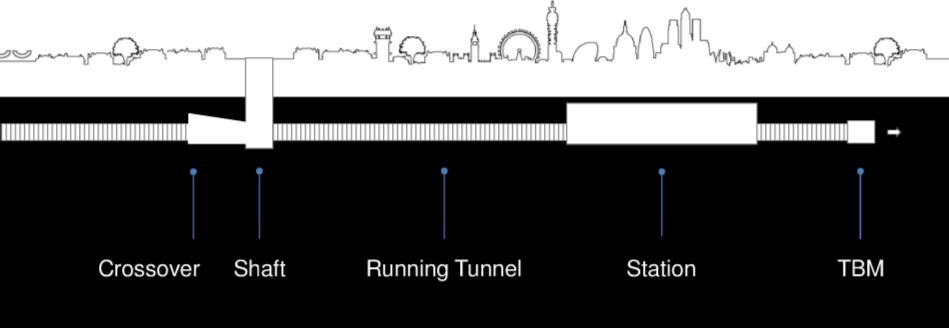
Figure 1.1 – Underground Structures in a Metro 1.1 Tunnels, Caverns, Excavations and Shafts
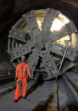
The Crossrail running tunnels have been constructed by two types of Tunnel Boring Machines (TBMs). The West (C300) and Central (C305) contracts used Earth Pressure Balance TBMs whilst the East (C310) used slurry TBMs. The geometry of all the TBMs were the same; a 12m long shield with mid shield articulation, 7.080m cutter head diameter configured to construct 1.600m long, 6.800m OD precast concrete (PCC) segmental tunnel rings. The TBM backup comprised a 20m long bridge behind the shield followed by 9 gantries, giving the TBM a total length of 120m. The TBM shield is in the region of 500Tonnes and backup gantries total approximately 1050Tonnes.
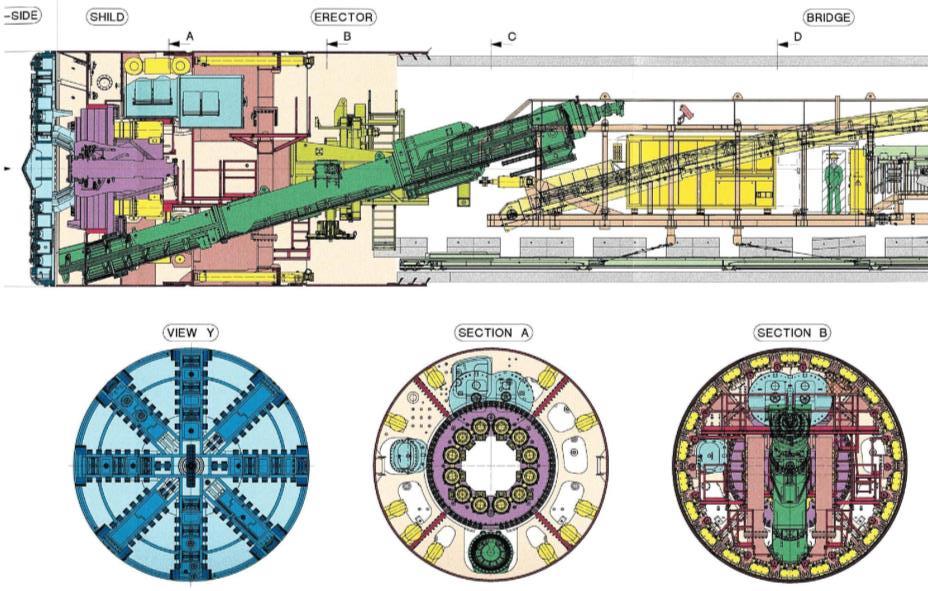
Figure 1.2(a) – TBM Shield and Bridge Sections 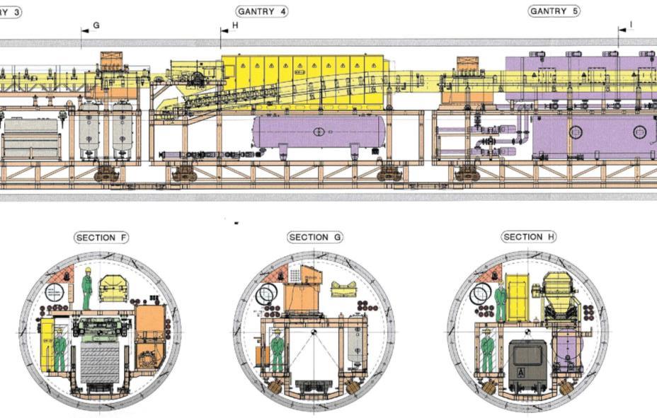
Figure 1.2(b) – Typical TBM Gantry Configurations Two methods were used to construct the underground station platforms. Stations were either mined with permanent sprayed or insitu concrete linings, or excavated as open boxes. Station platforms are typically 250m long and are set along a level and straight track alignment. The cross sections of a mined platform tunnel is a series of curves forming a “horse shoe” shaped cavern with an equivalent internal diameter of 12m. Structural lining thickness range between 800mm to 1200mm incorporating waterproofing membrane and in some cases bar reinforcement. The available cross section of box stations at platform level during the TBM transit can be up to 30m wide before the platforms and escalator structures are constructed. Shafts are either stand-alone structures or located at the end of the stations and can be sited on the track alignment. The cross sectional configuration of these shafts at track level where a TBM would transit vary depending on the internal structural layouts.
CRL Mined Stations - Whitechapel
- Liverpool Street
- Farringdon
- Tottenham Court Road
- Bond Street
CRL Box Stations
- Woolwich
- Canary Wharf
- Paddington
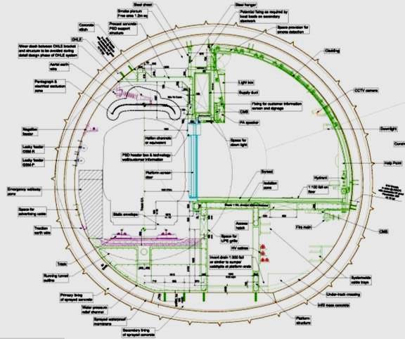
Figure 1.3(a) – Mined Station SCL Platform Tunnel Shafts on the track alignment are located at Limmo Peninsula and Stepney Green Junction where they were used to facilitate the launch and retrieval of the TBMs. In the permanent condition they are provided for ventilation and emergency egress / access.
Bifurcations accommodate the merger or splitting of the eastbound and westbound tracks. On Crossrail there is an underground bifurcation at Stepney Green junction where the north-east and south-east spurs meet. Crossovers on the other hand allow trains to switch between the eastbound and westbound tracks (and vice versa). There are two single crossovers on Crossrail, one located in the western section at Fisher street and the other on the central section immediately west of Whitechapel station. They are typically 125m long but have variable cross sections to accommodate the double track configurations. The maximum diameter of the caverns is 19m at the headwall.
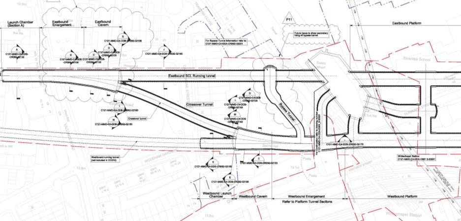
Figure 1.4 – Whitechapel Crossover and Durward St Shaft The summary above provides an insight to the type of structures that can be found on the track alignment and therefore along the running tunnel and TBM path. During the construction of the running tunnels, there is continuous stream of traffic within the completed sections of the tunnels for supplies, personnel and muck removal. There is no access to other Contractors along the running tunnels, including segregated sections of the station platform tunnels, during this time. It can therefore be appreciated how obtaining parallel access into the underground space can provide programme advantages.
The paper now discusses the design and planning of the particular operation of transiting TBMs through partially completed station platform tunnels. The two main risk are:
- Insufficient space for the TBM to transit through the station tunnels
- The station tunnels being constructed out of the permanent track alignment tolerance
2. TBM Transit Alignment
There are 4 alignments that need to be considered when designing the TBM transit:
- Permanent Track Alignment
- Tunnel Alignment
- TBM Transit Alignment
- Station Platform Alignment
All permanent works are referenced to Permanent Track Alignment. This is the most important principle to maintain. It is also a reminder that a Metro is primarily a railway which is contained within underground structures such as tunnels. The alignment of the underground structures must respect and satisfy the requirements of the railway. To achieve this, the Designer must understand the relationship and hierarchy between the various alignments.
2.1 Primary Alignment Relationship
The relationship between the Track and Running tunnel alignment is defined by a geometrical equation related to the track cant and the offset from the emergency walkway. The running tunnel axis (vertical alignment) remains at a constant offset to the track level because the pivot point is the track centre. This results in the tunnel centre line (horizontal alignment) being offset from the track centre line. This geometrical relationship can be seen below.
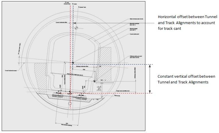
Figure 2.1 – Track / Running Tunnel Alignment Relationship In a station, the primary relationship is between the track and the platform edge. Track alignment in stations are normally straight and level, so the vertical and horizontal offset are constant. The track alignment could be related to the platform tunnel alignment like the running tunnel. However it should be noted that the cross sectional shapes of the station tunnels can vary along with the length of the station platform. Therefore forming a direct relationship between track and the station alignments in some areas is not straight forward. Nevertheless keeping the track alignment visible as a primary reference is important
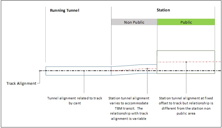
Figure 2.2 – Track Alignment Relationships 2.2 Secondary Alignment – TBM Transit
The secondary alignment as described here is simply the TBM transit alignment. The transit alignment is used to position the TBM within the station from which space proofing checks are undertaken. Through an iterative process, the TBM transit alignment is then adjusted to develop the final alignment. The TBM transit alignment iterations are usually isolated to the slew path locations where the TBM has to negotiate transit through sudden change of station cross sectional shapes. This occurs at the station headwall or at the interface with shafts.
The following section will provide some guidance for designing the TBM transit alignment. To begin with the following design principles should be incorporated where possible:
- The vertical offset between track level and TBM centreline should be kept constant.
- Horizontal TBM transit alignment is straight at the reception and launch locations
- The TBM transit slew is an “S” curves which should not bend the TBM in opposite directions at any one time
By keeping the vertical offset constant, the transit alignment also preserves the vertical offset from the track. This ensures the TBM and hence the PCC tunnels are constructed to the permanent track alignment. The TBM transit alignment iterations are then simplified by confining adjustments to the horizontal alignment only. It should be noted that this may not be possible if the running tunnels are constructed before the station tunnels. Here the vertical offset may need to be changed to position the running tunnel (pilot) at a particular level to facilitate the subsequent enlargement of the station platform tunnel.
Receiving and launching the TBM on straight horizontal alignments helps control TBM drive tolerance. Although arriving and launching on shallow curves was not an issue on C305, having straights simplified detailing for items such as the TBM launch brackets, transit rails and setting of station reception & launch chambers.
A horizontal “S” bend in the transit alignment is required to “slew” the TBM into and out of the station platform from the reception and launch chambers. The “S” bend is made up of three components comprising a curve, a straight and an opposite curve. The length of each component was matched to the TBM shield geometry as follows:
- Minimum curve or straight length = 12m
- Maximum curve radius = 400m
- Minimum station tunnel diameter = 7380mm
The curves were designed with entry and exit transitions. With this “S” bend geometry the TBM shield was not bent in opposite directions at any given time during the slewing. The TBM mid shield articulation was not considered in the transit design although could have been used if the tighter slew paths were required. Tighter radii and shorter lengths of curves and straights could have been used, but this would potentially cause the TBM swept path envelope to increase requiring larger diameter station tunnels. It should also be noted that the curve radius can be limited by the space required to transit the gantries. There is a risk that the bottom corners of the gantries frames clashing with the tunnel linings.
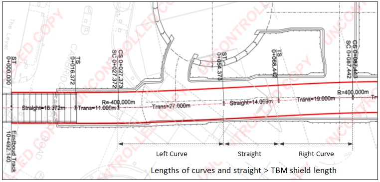
Figure 2.3 – “S” Curve Alignment Geometry 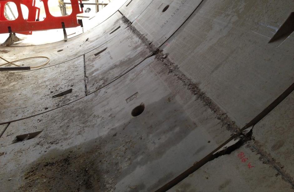
Figure 2.4 – Damage to PCC Segments from Gantry Clash (picture not from C305) The relationship of the TBM transit alignment can be related to the permanent track alignment by simply defining the horizontal offsets from the point where the two alignments depart. This relationship is essential for designing the station tunnels as it allows both the permanent and temporary space proofing to be checked simultaneously.
3. TBM Reception (phase 1)
The aim of reception chamber is to provide a controlled environment during the TBM break through and its subsequent transit into the station. In addition, space should be provided to facilitate the construction of the permanent connection between the Running tunnel and Station.
3.1 Controlling TBM Entry
An Earth Pressure Balance (EPB) TBM works on the principle that pressures at the face of the machine and around the cut annulus is maintained at a pressure equal to the pressure from the surrounding ground and ground water. During tunnelling, TBM face pressure is provided by ensuring the plenum (chamber between the cutter head and bulkhead) is kept full of excavated material (“muck”). This is achieved by balancing the rate of advance against the muck extraction rate. Similarly the annulus around the shield created by the over cut from the cutter head, is supported by hydraulic pressure in the form of a drilling mud (Bentonite). This is replaced by cement grout in the permanent case when the PCC tunnel linings are installed.
Face pressure is lost as the TBM begins its breakthrough into a station. When the cutter head daylights into the station, the annulus around the TBM shield is exposed to the atmosphere and hydraulic support can no longer be maintained. If no provision is made for alternative support, there will be a length of ground which is temporarily unsupported whilst the full length of the TBM enters the reception chamber. Until the last permanent tunnel ring is installed and sealed against the reception chamber, there remains a risk of the annulus collapsing and the ground above settling.
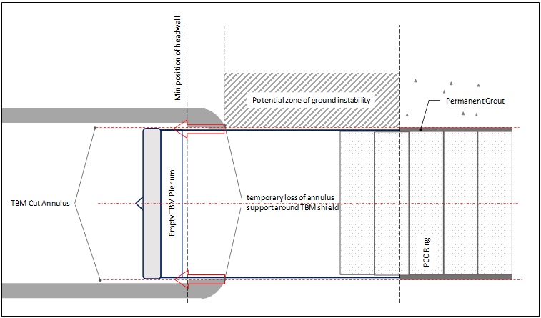
Figure 3.1 – Potential Loss of Support around TBM Shield at Reception The station reception chambers on C305 were SCL tunnels that extended from the station platform tunnel. The reception chamber headwall / “softeye” is a balanced design that provides temporary stability before TBM breakthrough but structural weakness during the breakthrough. This was achieved by using a dome shaped headwall constructed of a thin SCL shell which was stabilised by a foam concrete plug (C2 to C5 concrete) behind it. The SCL headwall is fractured by the applying tensile splitting forces on the concrete through the TBM disc cutters. This was typically 100kN per disc of which there were 22No. The foam concrete was a means of controlling the break through to avoid collapse of the headwall.
Once the TBM cutter head was buried into the reception chamber’s headwall, risk of ground movement ahead of the TBM face is prevented as the chamber provides a protective canopy. In stations such as Canary Wharf where the breakthrough was directly into a box, there was no ground ahead of the TBM face and hence no risk of ground collapse once the TBM was in the station. Collapse of the annulus around the TBM shield is caused by high pore pressures or flowing water which in turn destroys any temporary soil shear strength. The hydraulic support in the annulus during the normal TBM operation can be maintained after break through by providing seals inside the reception chamber. This can be achieved by having:
- Entry Seals system (Bull-Flex)
- Manual sealing of the annulus (“fluffing”)
- Extended concrete foam plug equal to TBM length + 1 PCC ring
Further annulus stability can be achieved by stabilising the ground immediately outside the reception chamber headwall for a minimum length of the TBM shield. This would include the use of:
- a grouted canopy
- depressurisation / dewatering of the ground
3.2 Alignment and Geometry
The horizontal alignment of the reception chamber should be straight for a length of the TBM shield plus 2 PCC rings. On C305 this was 15.2m (12m+1.6m+1.6m). A further length, typically 1m was provided for constructing the permanent connection collar.
The minimum clear diameter for the reception chamber was 7380mm. This was based on:
- current head diameter of 7080mm
- ±50mm TBM alignment tolerance on radius
- 100mm shield to reception chamber clearance on radius
Further allowances locally would be required for accommodating seals and tolerances for constructing the reception chamber.
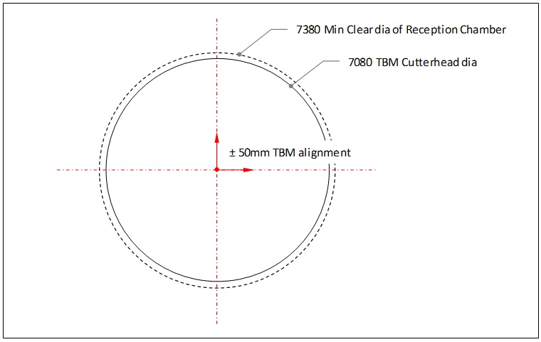
Figure 3.2 – Reception Chamber Clearances 3.3 Landing Platform
The TBM landing platform is essentially the invert of the foam concrete plug in the reception chamber. This provides a stable base for the TBM shield whilst preparations are made to transfer the TBM onto the transit rails in the stations. In box stations such as Canary Wharf where there were no SCL reception chambers, a foam concrete bed was prepared onto which the TBM bored into after breakthrough. There needs to be sufficient lateral support provided to these landing platforms to ensure that they are not pushed away or rotated during TBM entry.
From the time the TBM engages the station headwall, the reception chamber area became an exclusion zone. Dust suppression systems were provided at the headwall in the form of; water cannons, water sprinklers and additional ventilation. Control systems for the dust suppression and ground stabilisation were protected during TBM arrival by positioning the equipment outside the TBM envelope. Typically a gap of 1m was provided between the foam headwall (end of landing platform) and the beginning of the TBM transit rails. This gap has several functions including acting as a debris moat, sump and a transition zone to transfer the TBM on to the transit rails.
4. Station Platform Transit (Phase 2)
The transit begins with slewing the TBM into the middle of the larger platform tunnels. This is where the TBM departs from its tunnel design alignment. The TBM transit alignment design was discussed earlier and the slewing through a “S” curve generally occurs within the larger diameter station tunnels. Whilst it may appear that the station tunnels are much larger than its reception chambers, the thicker station linings and interface between different station cross sections results in “pinch points”. Here the TBM shield is close to the outer wall of the station tunnel for lengths up to 25m long.
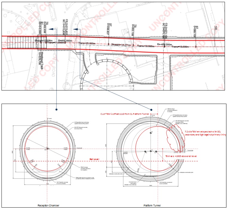
Figure 4.1 – Example of “Pinch Point” where TBM Enters Larger Platform Tunnel Once the TBM is in the main body of the station platform tunnels, there is little risk of clash. The main consideration here is related to integration and logistic of the temporary works in order to protect permanent works and optimise programme.
4.1 Space Proofing
The space proofing checks were undertaken using a range of TBM envelopes up to 7480m diameter. The review was first undertaken in plan and then specific clash checks done in cross section at critical points, paying particular attention to the curvatures of the station tunnels above axis. On C305, clash analysis was also undertaken in 3 dimensions by the TBM manufacturer, Herrenknecht, and by the C305 Contractor DSJV.
The Herrenknecht check was a review of the station temporary space proofing. It used the TBM design transit alignment and a range of TBM envelopes which were checked against the station 3D design models. However the station model initially, did not represent the intermediate configuration during the TBM transit phase. The station models were modified but specific details such as interface connections were difficult to model accurately. There was still tremendous value in undertaking this 3D modelling as it provided an independent check on the temporary space proofing, but more importantly a strong visual aid to focus minds on the specific issues at “pinch points”.
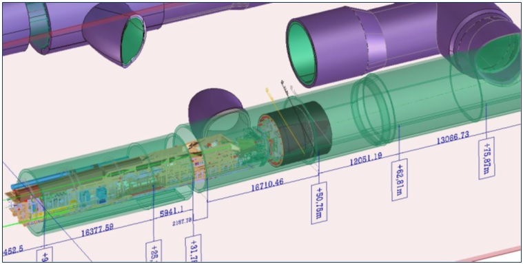
Figure 4.2 – Strong Visualisation Aid in 3D The DSJV 3D check was undertaken using built survey information of the SCL tunnel linings. With a clear understanding of where the “pinch points” were, targeted surveys and checks could be undertaken. As discussed previously, understanding the track, station and transit relationship here allowed the TBM envelope to be positioned correctly relative to the as built station lining survey. Thereafter this could be evaluated for clash and adjustment identified accordingly.
Localised clash can be addressed in several ways including:
- Detailing the curvature / geometry of the platform tunnel above axis
- Not constructing the secondary lining before TBM transit
- Increasing the diameter of the platform tunnel locally
The majority of the TBM transit occurs through main length of the station platform. Once the TBM has been slewed into the middle of the station platform tunnel and the transit alignment set straight and level, the risk of the TBM shield clashing with the station lining is minimal. Although there are still areas where particular clash checks are required including:
- interface junction between the platform tunnel and shafts
- tunnel sections with passage openings
- non public area tunnels where there is a change in cross section
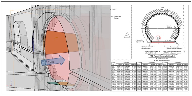
Figure 4.3 – (a) Local Clash at Shaft Tunnel Interface (b) Detailed Setting Out for Shaft Aperture Whilst positioning the transit alignment in the middle of the platform tunnel may present the lowest risk option for preventing clash, it may not necessarily be the optimum location when considering provisions for:
- Station platform construction programme
- TBM temporary works instillation (conveyors)
- TBM dismantling and removal of temporary works
- Construction of station first stage concrete
4.2 TBM Transit Plinths
The TBM shield and gantries have very different geometries and therefore requires two different types of support platforms. The TBM shield is supported on two outer rail plinths. The space left in between these plinths is then used for cradles that support the TBM gantries and temporary railway.
The initial sections of the transit rails were adjustable so that it can be aligned with the final position of the TBM shield when it breaks into the station. On C305 the adjustable transit rails were formed of prefabricated 50 x 50 mm flat bars tack welded onto a hollow steel sections filled with grout. These hollow steel section were welded onto a 12 mm plate with links at 250 mm centres, then cast into reinforced concrete plinth. After TBM breakthrough the tack welds could be removed to allow final adjustments to be made. The temporary plinths were separated from the station lining with a debonding membrane but dowels were provided at the interface to provide shear resistance.
Beyond the adjustable rails were the fixed transit rails which were formed of MRS 87A Rail or an 80 x 30 mm flat bar welded onto the 12 mm plate. The 80 x 30mm flat bar was used where clearance to the station tunnel lining was tight. All the transit rails were installed using a jig that was set out to the TBM transit alignment.
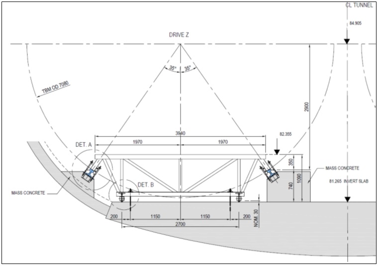
Figure 4.4 – Transit Rail Jig 4.3 TBM Jacking
The weight of the Crossrail TBM shield including its cutter head is just over 500T. The bridge and gantries were on average 50T each. The total weight of the complete TBM assembly is in the region of 1050T. The TBM shield is slid along greased transit rails and designed for a friction factor of 0.3 resulting in a horizontal force of 150T. The gantries run on wheeled boggies where additional horizontal forces of between 30T to 50T are estimated.
Two jacking systems were used on C305 to advance the TBM across the station which include using:
- TBM Rams to push off temporary invert segment
- Independent jacks attached to the TBM shield pushing off the transit guide rails
The first system of jacking off temporary invert ring (“shove iron”) was used in all the transits apart from Canary Wharf station. This was a simple systems that placed two invert PCC segments behind the TBM which provided a reaction point for the jacks to advance the shield forward. The invert segments were supported off the station tunnel invert on timber blocks positioned in between the transit rail plinths. These timber blocks were placed adjacent to the transit rail plinths outside the envelope of the TBM shield. Once the TBM shield had passed, the timber blocks were pulled into position by a system of ropes and wedged under the PCC segment. These invert segments then provided the temporary platform to support the TBM gantries and temporary railway as per the normal configuration in the running tunnel. Where the station tunnel invert or shaft inverts were deep, additional concrete was poured to build up a temporary invert. Where possible rectangular hollow sections were incorporated so that telehandlers could be used to remove the temporary invert after completion of the tunnelling works.
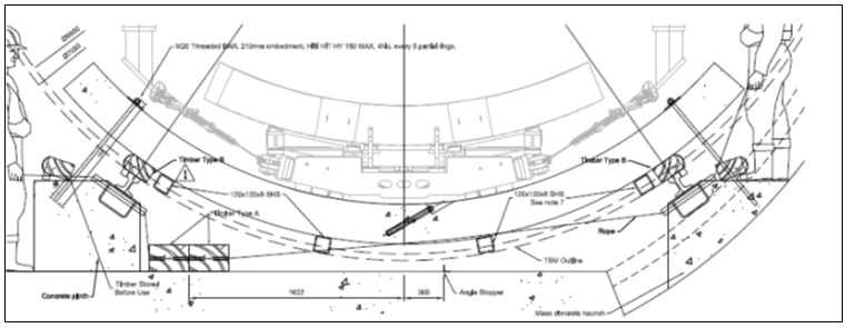
Figure 4.5 – TBM Shoving Off Temporary Invert Segments During Transit 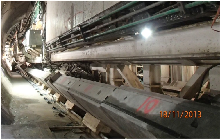
Figure 4.6 – TBM Gantries Supported on Temporary Invert Segment During Transit As a note, on C300 Western Running Tunnels, 1m long temporary segments where installed through the station platform to match the maximum advance length of SCL excavation for the subsequent enlargement of the station platform tunnels.
The second system used cradles on rail bogies to carry the TBM shield and its gantries across the station. Hydraulic jacks were welded to the body of the TBM shield and clamped to the transit rail. These jacks were then extended, unclamped from the transit rail, retracted and clamped again in sequence to advance the TBM. These temporary works were specially fabricated mechanical and steel components. The temporary railway was initially supported on a series of steel plinths along the TBM transit alignment but was later realigned to the outer edge of the station to segregate the station from the tunnel so that works on the platform could continue in parallel
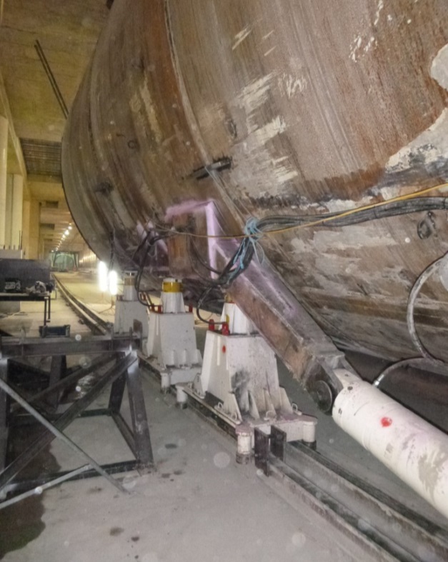
Figure 4.7 – Temp Hydraulic Jacks Advancing TBM 4.4 Tunnelling and Station Interface
The first jacking system where the TBM Rams were used to advance the TBM was simple. The temporary railway and TBM services could also be installed behind the TBM as it advanced in the usual way. The temporary works components in the station were standard items of steel rails, rebar, timber and insitu concrete. By contrast the use of cradles to move the individual TBM components in the second system was arguably more complicated but it allowed the station works to recommence earlier and continue in parallel with the tunnelling thereafter thus returning benefit to the project programme.
Planning the interface between the station and tunnelling works is important to allow both programmes to be optimised. However the various underground spaces should always be clear defined and controlled by the respective Principal Contractors. These work spaces would have its own arrangement for welfare, access routes, entry and emergency egress. The boundaries of the underground sites is dynamic so it was important that daily liaison between the Contractors’ “Person in Charge” were undertaken to confirm changes to the work areas and corresponding emergency arrangements. During tunnelling, the station space where the temporary railway is located is under the control of the tunnelling Contractor. No station works can be undertaken in this area until is it handed back to the station Contractor. Where possible the aim was to have the structural lining completed in the platform tunnels so that only internal works such as that for the platform structures and track bed would need to be undertaken after the platform tunnel is handed back.
Temporary services are required through the station to support the TBM. Lighting was positioned next to walkways by the transit rail plinths. Other services including pipework, electrical cables, communications, muck conveyors and ventilation were fixed to the station tunnel lining. Installation of the conveyors and ventilation bagging could not be undertaken from the TBM gantries without additional provisions in the form of extension chains being provided to account for the large diameter platform tunnels. Consideration could be given to using steel frames erected around the TBM on which these services could supported, keeping it independent of the station lining. Constraints such as temporary loads and drilling depth into the station linings were defined in Interface Control Documents to allow the tunnelling Contractor to design the temporary works whilst protecting the permanent works in the station. Items of particular concern to the station was preventing damage to the permanent structural lining and waterproofing membrane (if installed).
Upon breakthrough the ventilation through the completed tunnel needs to be preserved. This could be provided by venting through the stations, but in the case of C305 the system was sealed so that air circulation was contained within the running tunnels. This approach therefore required bulkheads to be erected across station openings, such as adits and shafts. In some cases where the station was not ready for TBM transit, temporary bulkheads were erected across the platform tunnel itself.
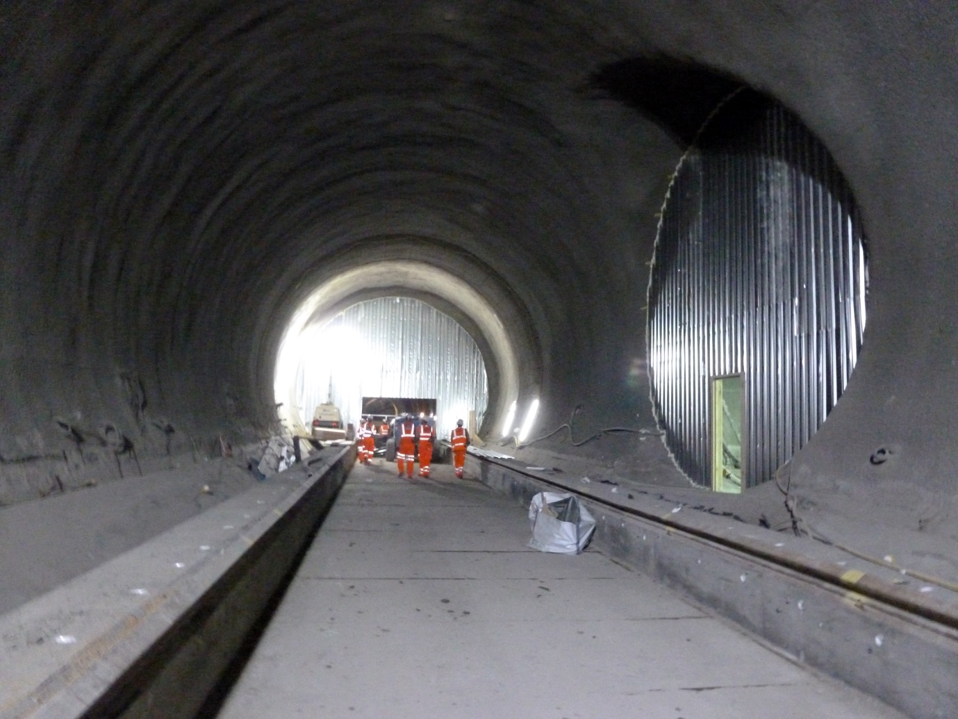
Figure 4.8 – Temporary Bulkheads for Ventilation Tunnel Ventilation Further programme optimisation can be achieved by integrating the tunnelling temporary works with the station permanent works. Reducing the amount of temporary works removals brings benefit to the project programme, reduced access requirements and risk of damage to the station permanent works. Apart from the interface with the station tunnel lining, the other interface between the tunnel temporary railway is the platform structure and the track bed concrete. Positioning of the temporary works would need to take into consideration position of reinforcement, undertrack crossings, track drainage and so on. Furthermore the construction of cast in items would require the works to be adopted by the permanent works Designer who in doing so needs to ensure that track and platform setting out are preserved. This is where maintaining an understanding between the permanent track alignment and the other temporary alignments is key to ensuring the permanent railway requirements are achieved.
Whilst undertaking tunnelling and station works in parallel may bring programme benefits to the project, there must be a clear understanding of how the TBM will be retrieved at the end of the drive. The construction of the platform structure in the station reduces the available space if large TBM components have to be retrieved back through the station. Consideration should then be given to the configuration of the temporary works such as the use of steel vs concrete, insitu vs precast, in order to understand which approach optimises the time required for temporary works removal and hand back of the station space.
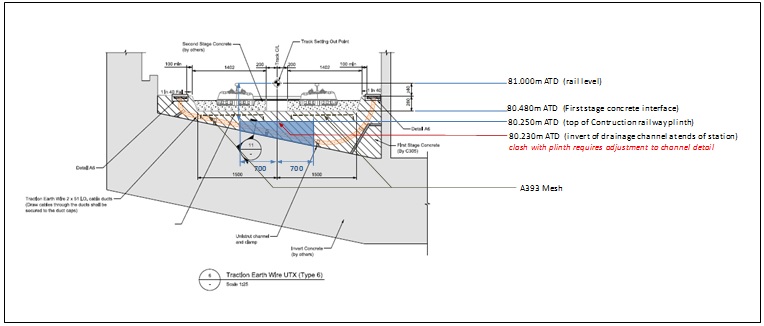
Figure 4.9 – Example of Integrating Temporary Railway Plinth into Station First Stage Concrete 5. TBM Launch (Phase 3)
The aim of launch chamber is the same as that of the reception chamber but in reverse. It provides a transition length to reset the TBM on the permanent tunnel alignment and a stable environment thereafter to break out of the station. The design of the launch chamber must therefore have provision for:
- transition the TBM from the platform tunnel back onto the design tunnel alignment
- housing the launch brackets against which the permanent tunnel rings are constructed
- Sealing the tunnel allowing full face pressure to be established before break out
- constructing the permanent connection between the Running tunnel and Station
Although the TBM can launch on a horizontal curve the preference is always to have a straight alignment wherever possible. On C305 launch chambers were constructed at the end of the bored stations for a length of the TBM shield plus 1m for a foam concrete plug. Behind the shield a further length is required to accommodate the launch brackets and provision for constructing the permanent connection between the PCC rings and the station lining.
The minimum clear diameter for the launch chamber was 7280mm. This was based on:
- current head diameter of 7080mm
- 50mm alignment tolerance on radius
- 50mm shield to launch chamber clearance on radius
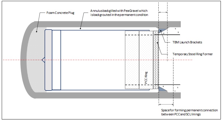
Figure 5.1 – TBM Launch Chamber Reaction Frame The diameter of the launch chamber is smaller than the reception chamber to minimise the size of the annulus grouting required around the permanent rings. This is to ensure a seal can be formed during the launch and the PCC rings are stabilised thereafter. On C305, reaction brackets aligned with the 22No TBM RAMs, were bolted around the launch chamber lining. Local thickening of the launch chamber lining was required to accommodate these brackets and to dissipate the launch loads. The launch loads were typically 200T from the dead weight of the TBM and a further 220T for the forced required to fracture the head wall. Further allowance were made to account for unevenly distributed RAM loads. Each launch bracket was made up of two steel components, a seat and a reaction frame, which were assembled together once the TBM shield was in position.
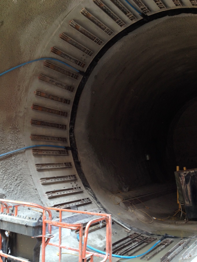
Figure 5.2 – (a) Launch Brackets Seats 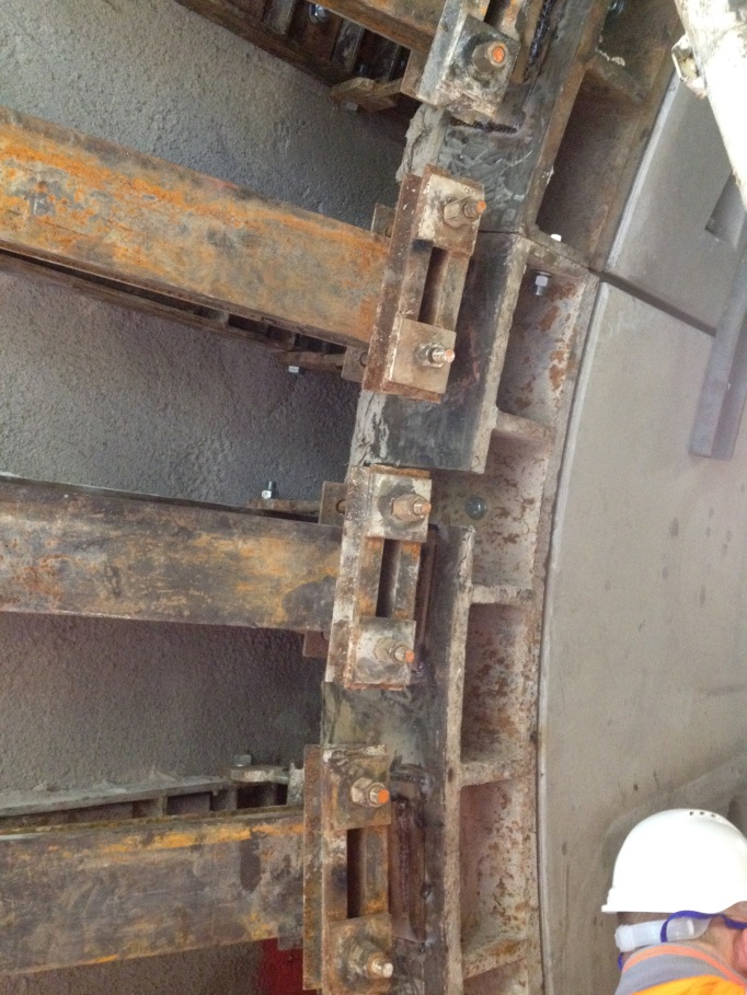
Figure 5.2 – (b) Fully Assembled Reaction Frames A 250mm wide steel ring former was bolted to the first PCC ring which acted as a template to aid assembly of the first permanent ring. As the PCC rings were built, a grout bag was installed at the trailing edge of the first ring in the annulus. This was inflated which formed a stop end against which the annulus could be backfilled. The annuls back fill within the launch chamber was initially pea gravel which was then grouted once the TBM broke out and tail skin grouting could begin. The configuration of the foam plug and the shape of headwall had a bearing on how easy it was to breakout. The preference was:
- No steel fibres in the headwall concrete to avoid concrete breaking into “clumps” making it difficult to remove through the muck screw.
- A benched rather than domed headwall to minimise concrete “clumps” during break out.
6. Conclusion
Developing the relationship between the TBM transit alignment and the track alignment is key to ensuring the permanent works are not compromised. The transit alignment should be kept simple by maintaining the vertical alignment at a constant offset from the permanent track alignment thus confining to design of the transit to the horizontal alignment. Where possible, allow the TBM to be received on a straight alignment. During the transit avoid short “S” curves as this would require the TBM to bend in opposite directions simultaneously.
Clash detection can be done very accurately in 3D and its results serves as a very powerful visual aid. However it relies on having equally accurate information about the station lining configuration in the intermediate state. The primary clash checks should be undertaken using discrete sections at critical locations. This is more precise and allows setting out of the station tunnels and apertures to be defined accurately.
The TBM station transit can be described in three parts; reception, transit and launch. The main risk during TBM reception is ground instability. The TBM face and annulus pressures that are lost during entry can be mitigated by providing seals in the reception chamber and undertaking ground stabilisation. During the TBM transit, areas of risk to TBM clash include locations where the station cross section changes and where the TBM transit path slews away from the track alignment. There are several ways of optimising the tunnelling and station programmes such as integrating the tunnelling temporary works with the station permanent works and using segregated work areas to allow parallel working to continue safely. However this has to be balanced against the potential impact on access required for other works such as TBM removal. Access into the underground space is always limited and therefore the use of a simple light weight launching system was ideal.
C305 under took four TBM transit through stations and crossover chambers. A simple and repeatable system was used which allowed all the transits to be completed without major issues. Design, planning and execution of the works required extensive interfacing to achieve a balanced outcome for all parties. Successful transits of the TBMs through the stations was a key component for maintaining the critical path activity of constructing the running tunnels.
-
Authors