Temporary Sprayed Concrete Lining Tunnels in Farringdon Crossrail Station
Document
type: Technical Paper
Author:
Angelos Gakis Dr. Dipl-Ing, MSc DIC, CEng MICE, Petr Salak Eur Ing, MSc, CEng MICE, Adrian St.John, BEng (Hons) Eur Ing FICE CEng, ICE Publishing
Publication
Date: 07/09/2015
-
Read the full document
Notation
ALARP As Low As Reasonably Practicable BGS British Geological Survey BFK BAM Ferrovial Kier Joint Venture, the main contractor CH1 Concourse Chamber 1 CP1 Cross Passage 1 DSP Dr. Sauer & Partners, specialist SCL designer for BFK ES1 Escalator Barrel 1 FE Finite Element FEA Finite Element Analysis ko Earth Pressure Coefficient at Rest LC London Clay LMB Lower Mottled Beds LSB Lower Shelly Beds LTB Laminated Beds MLGH Mid Lambeth Group Hiatus OTB OTB Engineering Ltd, the CAT III Checker for the temporary SCL structures PL1 Platform Extension Tunnel 1 PL2RC Wraparound tunnel connection westbound TBM and CP1 PTW Platform Tunnel West SCL Sprayed Concrete Lining SFR Steel Fibre Reinforced SH-W1 Shaft West 1, Main SCL access shaft STW Stub Tunnel West (1 and 2) TBM Tunnel Boring Machine TS Thanet Sand TM Tunnel Metre (i.e. chainage) UF Upnor Formation UMB Upper Mottled Beds Project Overview
Crossrail is a new railway system which will provide a connection between the South-East and the South-West railway networks through the centre of London. The Crossrail route will run from Shenfield and Abbey Wood in the east through 21km of twin-bore tunnels under central London – connecting key London stations including Canary Wharf, Whitechapel, Liverpool Street, Farringdon, Tottenham Court Road, Bond Street and Paddington – and out to Reading and Heathrow in the west. Crossrail is among the most significant infrastructure projects ever undertaken in the UK.
Around 200 million passengers will travel on Crossrail each year and the route will provide a 10% increase to rail capacity in the capital. Farringdon station is situated at the heart of London’s rail network and will be one of London’s major rail interchange stations. Millions of people travelling to and through London will benefit from Farringdon station, which links Crossrail, Thameslink services and London Underground trains.
The station also played a distinguished role in the construction of the Crossrail project: it was intended to receive four earth pressure balanced tunnel boring machines (TBMs): the two Drive X TBMs, running from Royal Oak to Farringdon and the two Drive Y TBMs, running from Limmo to Farringdon (Figure 1).
The Farringdon station layout included two ticket halls, two escalator inclines, two platform tunnels, connecting cross passages, concourse tunnels and ventilation adits. The chosen tunnelling system for Farringdon Station was sprayed concrete lining (SCL), a sequential open face tunnelling method. The primary linings were constructed using steel fibre reinforced (SFR) sprayed concrete; the secondary linings were cast in-situ concrete in combination with a sheet waterproofing membrane. The station comprised a total of 1km of SCL tunnels at depths of up to 35m below ground level and excavation cross-sections varying from 25m2 to 110m2.
Crossrail awarded the contract for the construction of the Farringdon Crossrail station to a joint venture of BAM Nuttall, Ferrovial Agroman and Kier Construction (BFK) in 2011. BFK appointed Dr. Sauer & Partners (DSP) as specialist consultant responsible for the design and supervision for all sprayed concrete lining (SCL) tunnelling works prior to ring closure and all temporary tunnels in all stages.
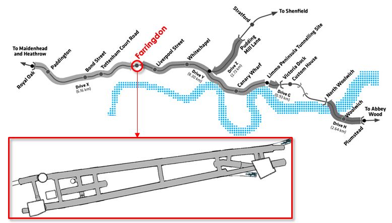
Figure 1 – General view of the Crossrail route with focus on Farringdon station
Introduction
One of the key challenges for the SCL project team at Farringdon was the integration of the logistics and managing the programme interface with adjoining works. The project benefited from the fact that the BFK Joint Venture had been awarded Crossrail Contract C300/C410, the Western Running Tunnels and Station Caverns, as well as Crossrail Contract C435, Farringdon Station. Whilst these were administered as separate contracts, key personnel from BFK operated across both projects, which permitted effective management of this interface and enabled significant cost and time savings to be generated for the benefit of Contractor and Client alike. For example, the BFK initiative to “turn and bury” the C300/C410 TBMs generated a net benefit of £3.7m and 5 months on the programme across the two contracts. This proposal also significantly de-risked the programme by removing the critical interface between TBM extraction and construction of the Farringdon Eastern Ticket Hall.
The SCL works at Farringdon were significantly impacted by two major interfaces:
- The arrival of the two C300/C410 TBMs at the Farringdon western ticket halls. The TBMs would then transit through the ticket halls and bore large diameter precast concrete pilot tunnels through the platform areas in preparation for subsequent enlargement to full platform size using SCL techniques.
- The construction of the shafts for the Eastern Ticket Hall and Western Ticket Hall which would provide primary underground access to construct the SCL works.
Both of these interfaces had a profound effect on the project and this paper explains how the design and construction of additional temporary SCL structures has led to significant optimisation of the SCL programme and substantial cost savings.
Original sequence
One of the inefficiencies within the SCL construction programme was a four month hiatus in the SCL works caused by the arrival of the C300/C410 TBMs. The original plan was to undertake a period of “pre-TBM” SCL works; this early SCL work entailed the construction of a soft eye to receive the TBM at the bottom of the circular shaft (SH-W1), together with stub tunnels STW1, STW2, platform extension tunnel PL1 and cross passage CP1 (see Figure 2). CP1 would be terminated at a temporary headwall approximately 5m north of the junction with PTW.
The SCL works would then be suspended upon the arrival of the eastbound C300/C410 TBM, as the main SCL access shaft, SH-W1, would be backfilled with foam concrete. They could only recommence once the TBM backup gantries and logistics and the shaft backfill had been fully removed. Upon recommencement, the SCL team would enlarge the TBM pilot tunnel (6.2m internal diameter) to the full 10.5m high by 11.5m wide tunnels required for the platforms. Once enlarged, junction thickenings would be created which would permit subsequent breakout between the parent-child tunnels. In other words, it would be some considerable time before CP1 and PTW could be connected.
This sequence was clearly impacted by, and impacted upon, the Ticket Hall shaft construction and the TBM arrival and completion dates. The four month hiatus would also have meant the demobilisation of the SCL mining gangs, resources, plant and specialist equipment both on the surface and underground; not only was this a costly and inefficient exercise, the BFK team were also acutely aware of the high demand within London for specialist SCL personnel at this time. In an overheated labour market with an “anti-poaching” policy across Crossrail, the project team were concerned that they would not be able to successfully remobilise and train the required personnel to execute the next stage of the SCL works. This was a considerable risk for the project.
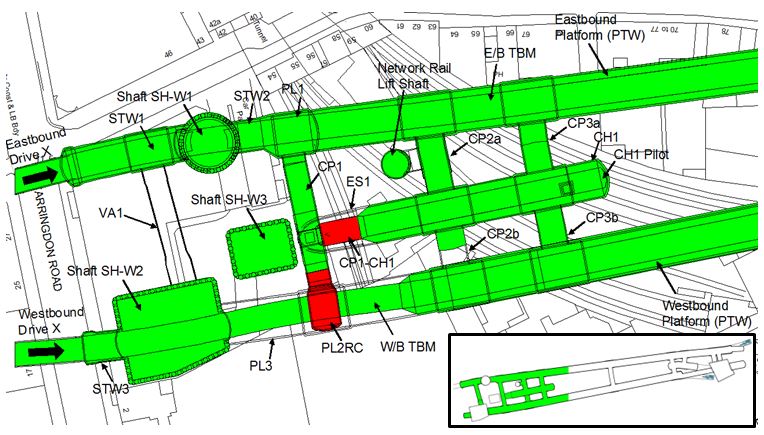
Figure 2 – Plan View of the West part of Farringdon station showing the location of the two temporary SCL structures (shown in red). The areas in green show the structures completed by September 2014
Revised sequence
With these challenges in mind, the project team, supported by their specialist SCL designer, DSP, sought to find a way to provide continuity of work for the SCL mining and supervision gangs and deliver efficiencies within the programme.
The team identified two key areas where improvements could be made over the base scheme. The key idea was to provide early access to the SCL works, connecting the westbound TBM tunnel to cross passage CP1 and subsequently to provide a temporary connection via CP1 to construct the concourse chamber CH1. The CH1 would start with an SCL pilot tunnel, followed by extensive radial probing and enlargement.
The incorporation of a temporary SCL tunnel connecting CP1 with CH1 (called CP1-CH1) would thus enable CH1 to be constructed much earlier in the programme, rather than waiting for access from the Western Ticket Hall shaft (via escalator barrel ES1). This specifically enabled the CH1 pilot tunnel to be constructed concurrently with the westbound TBM works.
Furthermore, an additional temporary “SCL wraparound” chamber (called PL2RC) at the southern end of CP1 would permit a rapid and efficient connection to be created between the westbound TBM and CP1. This would enable the SCL works for the probing and enlargement of PTW to commence much earlier in the programme. Moreover, by switching the logistics routes, this then allowed the probing and enlargement of CH1 to take place concurrently with the eastbound TBM drive.
Ultimately, these two structures provided a versatile solution that introduced an alternative connection between the TBM and the SCL works, allowing the latter to progress undisturbed between November 2013 and March 2014, when the main access shaft, SH-W1, was backfilled with foam concrete awaiting the arrival of the eastbound Drive X TBM (3/12/2013).
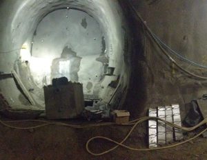
A panoramic view of CP1, CP1-CH1 temporary connection adit and PL2RC is shown in Figure 3.
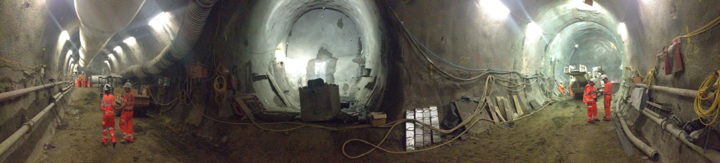
Figure 3 – CP1 (left), CP1-CH1 connection adit (centre) and PL2RC (right)
Benefits of the revised sequence
The benefits of such an arrangement were manifold and included:
- Re-routing the logistics via CP1-CH1 and PL2RC enabled concurrent working between the SCL works, the TBM drives and the Ticket Hall construction. This saved approximately 4 months on the programme.
- De-risking the programme by eliminating or reducing the interdependencies between the adjoining work activities (the SCL works, the progress rates of the eastbound and westbound incoming TBMs, and the progress of the shaft construction). This was of particular importance given the uncertainty over the C300 TBM arrival dates at Farringdon.
- Permitting continuity of SCL works, thus avoiding costly and inefficient demobilisation and remobilisation.
- Retention, training and development of key SCL operatives in an over-heated labour market.
- Avoidance of significant additional cost, estimated to be several million pounds.
On the basis of the above concept, and in agreement with the Crossrail project management team, BFK instructed DSP to design and check these two additional temporary SCL structures within challenging timescales to support the BFK construction programme. DSP employed OTB to carry out the independent Category III checks.
Design development
Concept, construction sequences and key dimensions
One of the key reasons for the successes at C435 Farringdon station was that the small but flexible and effective DSP design team were based on site and embedded into the BFK team. This enabled close communication and alignment between the construction and design teams and enabled DSP to be fully engaged in the development of these new concepts. This was particularly important given the short timescales required for design and checking in order to support the construction programme. The original concept was therefore detailed in conjunction with the BFK site team.
PL2RC wraparound was constructed at the southern end of CP1 approximately perpendicular to the westbound TBM alignment. The function of the structure was to allow rapid connection between CP1 and the TBM tunnel. The wraparound structure was formed of a sprayed concrete chamber approximately 9m high by 8m wide, together with a flared transition from CP1 to this chamber and a headwall (Figure 4). The primary sprayed concrete lining of PL2RC was initially sized as being 350mm thick SFR shotcrete. Once constructed, the chamber was backfilled with foam concrete, which permitted the westbound C300/C410 TBM to rapidly transit through the chamber; subsequently the foam concrete backfill and the segments were partially removed to provide the connection.
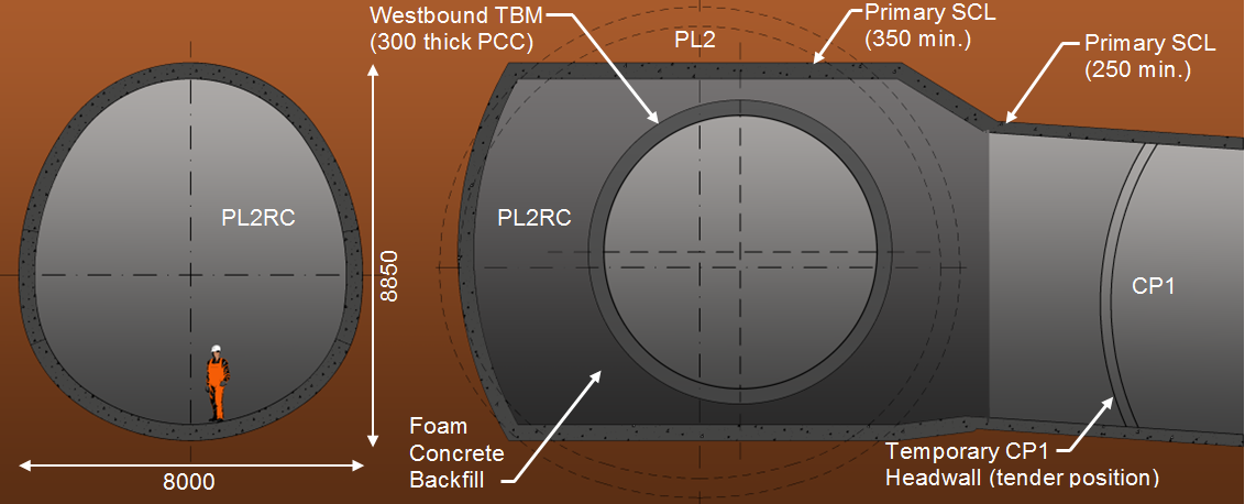
Figure 4 – PL2RC cross section (left) and longitudinal section (right)The construction sequence of PL2RC was developed as follows (Figure 5):
- Excavation/primary lining of CP1
- Excavation/primary lining of the transition from CP1 (excavation area 36m2) to PL2RC (excavation area 57m2)
- Excavation/primary lining of PL2RC and the headwall (Figure 5 left)
- Back-filling PL2RC with foam concrete
- Passage of westbound TBM pilot tunnel through PL2RC (Figure 5 right)
- Establishment of connection between CP1 and westbound TBM
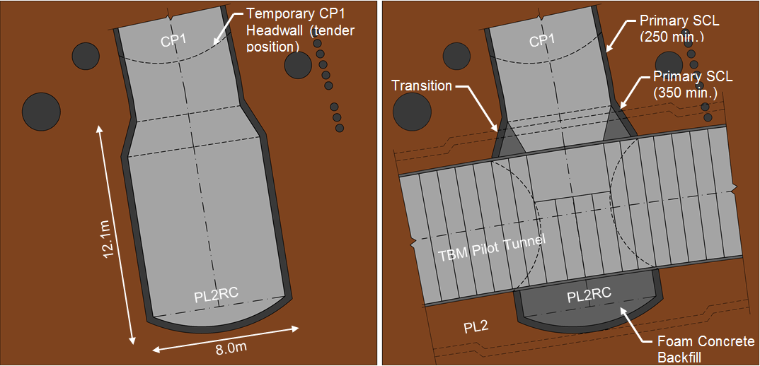
Figure 5 – Initial stage after the completion of the construction of PL2RC (left) and final stage, after the passage of the westbound TBM, the partial removal of foam concrete and the break in to TBM Pilot tunnel to create access for PTW/PL2 Enlargement works (right)The CP1-CH1 connection adit was approximately 7m high by 6m wide and was constructed through a small opening in CP1. The primary sprayed concrete lining of this adit was originally sized as being 250mm thick (see Figure 6). This connection allowed CH1 to be built in advance of escalator barrel ES1, providing significant programme savings. The tunnel and the opening in CP1 would be subsequently backfilled to reinstate the primary lining in CP1. This would be followed by the construction of ES1 through the backfilled CP1-CH1 connection adit and the permanent connection between ES1 and CH1.
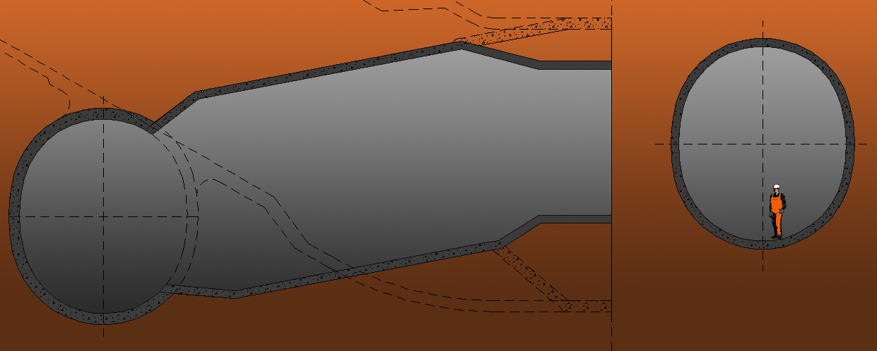
Figure 6 – CP1-CH1 longitudinal section (left) and the cross section (right)
The construction sequence of the CP1-CH1 connection adit was developed as follows (see Figure 7):
- Excavation/primary lining of CP1 and 350mm local thickening for the break-out was applied as excavation proceeded (Figure 7 left)
- Breakout of CP1 to form the CP1-CH1 temporary connection
- Excavation/primary lining of CP1-CH1 connection adit (Figure 7 right)
- Excavation/primary lining of CH1 pilot tunnel
- Excavation and removal of CH1 pilot tunnel/enlargement to form primary lining of CH1
- Backfill the CP1-CH1 temporary connection adit with foam concrete
- Reinstate primary lining in CP1
- Construction of ES1, including mining through backfilled element of the CP1-CH1 connection adit, to form the final connection between ES1 and CH1.
Agreement of these key elements enabled detailed design and modelling to commence. Evolution of the design was checked periodically through design reviews and buildability reviews with the Contractor’s site team.
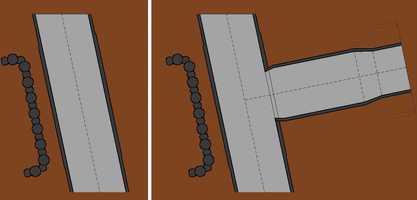
Figure 7 – Initial stage before CP1-CH1 construction (left) and final stage, after its construction providing the connection between CP1 and CH1 pilot (right)Design review and buildability reviews
These detailed reviews were undertaken jointly by the DSP and BFK teams to ensure that the evolving design would deliver a safe and functional solution, tailored to suit the Contractor.
The size of the Contractor’s plant and the C300/C410 TBMs had a profound effect upon the spaceproofing. The size of PL2RC was dictated mainly by the size of the TBM; the CP1-CH1 connection adit spaceproofing was governed by the size of the construction plant and the layout of the station.
CP1-CH1 was particularly difficult from a constructability perspective since the cross section of CP1 was prescribed by the permanent works design and was driven by the close proximity of the future escalator barrel ES1 (see Figure 6). This was a limiting factor and resulted in a fairly small break-out from CP1 towards CH1, which flared out right after the break-out to allow more space for the tunnelling operations. Due to the layout of CP1 and CH1 the break-out was aligned with CH1 and the future ES1. The 90 degree junction between CP1 and CP1-CH1 connection adit, combined with the small size of both tunnels caused considerable challenges in terms of plant movements and logistics. The final arrangement was less than optimal but a necessity based on the above constraints.
The DSP and BFK teams worked closely together to develop detailed excavation sequences for both tunnels. The preferred option was a simple top heading, bench and invert sequence without the use of a pilot tunnel within the larger PL2RC. This was possible due to good knowledge of the ground conditions through the use of a 3D geological model (described in section “Geotechnical review and risk management“). To provide an uncomplicated passage of the TBM through the wraparound, its primary lining was optimised to a thin, 350mm shell and it was subsequently backfilled with low strength foam concrete. Also the use of bar reinforcement across the longitudinal joints between top heading, bench and invert were omitted in PL2RC to avoid causing damage to the TBM cutter head during its transit.
The Contractor’s strong preference to solely use SFR shotcrete linings throughout both structures provided significant health and safety benefits; namely obviating the need for personnel access to the face, maximising the amount of mechanisation, reducing manual handling and eliminating working at height. One of the key challenges for DSP was to deliver this concept with a fully designed, checked and assured SCL lining design fit for construction within the given timeframe still allowing for the contractual review periods from all parties.
As the design evolved, the following geometry was developed:
- The PL2RC chamber, 8850mm high by 8000mm wide, was subdivided into a 4500mm high top heading, with a 2500mm high bench and a 1850mm high invert.
- The CP1-CH1 connection adit, 7200mm high by 6200mm wide, was subdivided into a 4000mm high top heading, with a 2000mm high bench and a 1200mm high invert.
The excavation sequence was the same for both tunnels and consisted of 2no.1m long top headings, followed by 1no. 2m long bench and 1no. 2m long invert, providing a minimum stagger of 1m between the faces at all times. This solution provided the most effective compromise between face stability and rapid ring closure minimising in-tunnel convergence and surface settlement.
Geotechnical review and risk management
Unlike the majority of the SCL works in London, the tunnels in Farringdon were constructed predominately in the Lambeth Group. The Lambeth group formations were confined by the London Clay (LC) at the top and the Thanet Sand formation (TS) at the bottom and comprised mainly stiff to very stiff, overconsolidated clays. In the area of the station, the formations of the Lambeth Group encountered were the Upper Mottled Beds (UMB), overlying the Laminated Beds (LTB) and the Lower Shelly Beds (LSB), followed by the mid Lambeth Group Hiatus (MLGH) and the Lower Mottled Beds (LMB). At the bottom, a layer of Gravels separated the LMB and the Upnor Formation (UF). Figure 8 shows face photos from the top heading, bench and invert excavation of PL2RC with the typical units that were encountered.
The main geotechnical risk for the SCL works in Farringdon arose from two factors; the possibility of encountering water-charged sand lenses of unknown pore water regime, geometry and spatial distribution in the UMB and the presence of four major faults crossing the footprint of the station, which affected the thickness, the elevation and the stratigraphic continuity. Specifically for the two temporary tunnels, PL2RC and CP1-CH1, the baseline data indicated a high likelihood of encountering the Farringdon Fault.
In order to reduce these risks to an ALARP level, the project’s team implemented an optimised geotechnical risk management methodology (presented extensively in [6]), which entailed a combination of thorough and systematic in-tunnel probing, the collection of data from face mapping records and the use of a constantly updated 3D geological model.

Figure 8 – Face mapping photos and geological unit description for the top heading, bench and invert stages of PL2RC, presenting the typical units of the Lambeth Group.This 3D geological model for Farringdon station was originally developed by BGS in 2009[1] and was handed over to BFK/DSP in 2013 in order to update it and incorporate it into the site supervision workflow. Data from the tunnel excavation works were thereafter added into the model on a daily basis (see Figure 9) enabling geological predictions of increasing accuracy.
The combination of these risk management tools was the key in predicting the expected geological conditions ahead of the excavation of PL2RC and CP1-CH1. Most importantly, it was assessed that the Farringdon Fault would not near the two tunnels and that the risk of encountering water-bearing sand lenses in the UMB was rather low. These key observations were valuable drivers towards an optimised design for both tunnels.
Figure 10 shows in plan view the location of the major faults and the extent of the sand lenses in the UMB as predicted by the 3D geological model from the British Geological Survey (BGS) in 2009, and as it has been updated by BFK/DSP based on the outputs of the evolving 3D geological model.
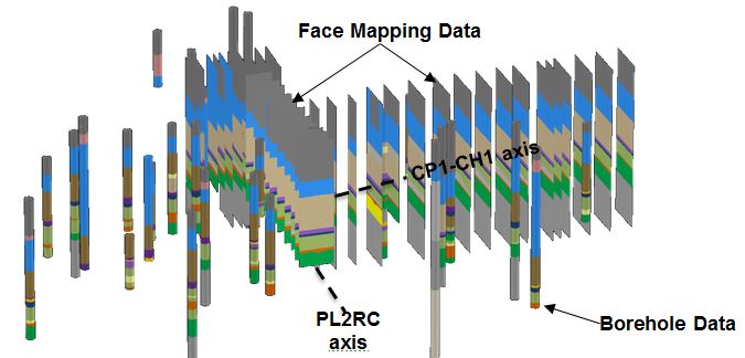
Figure 9 – Data from face mapping and borehole investigation integrated in the 3D Geological Model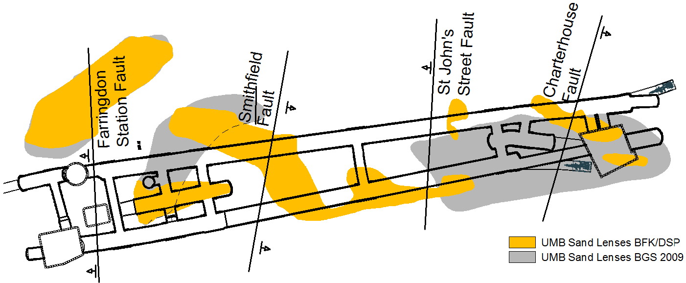
Figure 10 – Plan view of the station showing the projection of the Faults at tunnel axis level and the Sand lenses
Design Execution
In order to assess the capacity of the sprayed concrete linings and openings of the two tunnels, non-linear 3D FE analyses were carried out using ABAQUS v.6.12 (Dassault Systemes Simulia[4]). The sequential excavation and lining installation were modelled using a multi-step approach following the selected excavation and support sequences. Data provided by the latest update of the 3D geological model were used to simulate the geological conditions as accurately as possible.
Figure 11 shows a perspective view of the structures that were considered in the FE analysis for PL2RC.
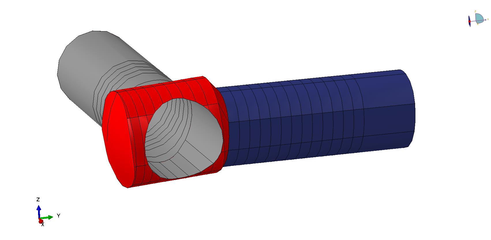
Figure 11 – Perspective view of structures included in the 3D FE model for PL2RC
Design parameters and assumptions
The FE mesh utilised linear tetrahedral solid elements to simulate the soil units and linear triangular shell elements to simulate the SFR shotcrete primary lining in multiple analysis steps.
The elastic-perfectly plastic Mohr-Coulomb model was used to simulate the behaviour of the continuum soil elements, due to its simplicity in the derivation of the required parameters and interpretation of the results. However, since Mohr-Coulomb is not a tailor-made model for unloading problems such as a tunnel excavation, additional considerations were manually incorporated in order to capture advanced constitutive modelling features. Specifically:
– Following the results of preliminary 2D FE calibration analyses performed using the FE software Phase2 (RocScience), the variation of stiffness with the strain level was taken into account, assuming a higher strain level in the proximity of the tunnel excavation and a lower strain level for the remaining areas.
– Depth-dependent strength and stiffness parameters of the soil materials were assumed.
– Increased stiffness was assigned to the unloaded soil elements under the tunnels’ invert.In addition, two values for the earth pressure coefficient at rest were used in separate models, ko=1.2 and ko=0.6; the first produced the critical case in terms of lining stresses and was therefore used in checking the lining capacity, whereas the latter produced more realistic in-tunnel and surface deformations and was used for the deformation predictions (similar conclusions are presented in [5]).
Undrained conditions were assumed in the clayey units due to the “fast” construction in comparison to the time required for consolidation, and the SCL lining was considered permeable in the short term, hence no water pressures were applied. The lining of PL2RC was also checked for the effect of compensation grouting loads. The soil parameters used in the FE models are listed in Table 1.
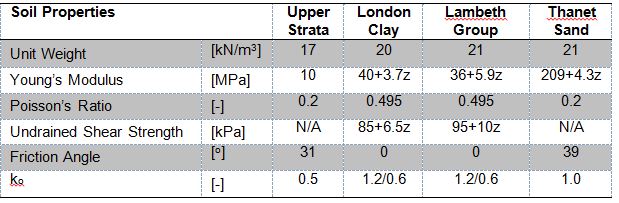
Table 1 – Soil Parameters used in the FE models. Drained parameters were used for the Upper Strata and the Thanet Sand units, and undrained parameters were used for the London Clay and the Lambeth Group units. Z denotes the distance from the top of the London Clay layer
The behaviour of the SFR shotcrete was simulated using the elastic-plastic “concrete damaged plasticity model”[4], according to which the material behaves as ideally elastic prior to compressive and tensile yield. The post-yield state accounted for the residual tensile strength parameters and the 28-day compressive strength. Exploiting the residual flexural strength of the SFR shotcrete was the key to designing thin lining without any reinforcement requirements. This advanced approach had been successfully applied on previous DSP projects and was embraced by the project’s team as the optimum solution. Also, the time dependent hardening of the shotcrete was considered in the elastic modulus using a hypothetical stiffness value [7],[8]. The parameters used in the FE models are listed in Table 2.
Table 2 – SFR shotcrete parameters used in the FE models
Both soil and the SFR shotcrete parameters were taken in accordance with the Crossrail Design Statement for Temporary SCL Works[2].
SCL capacity check
The capacity of the SCL primary lining was checked using capacity limit curves[10] following the design methodology for sections under axial load and bending from RILEM[9] and in accordance with the Crossrail Civil Engineering Design Standards[3]. Figure 12 shows the capacity limit curve for the 350mm thick PL2RC primary lining after the passage of the westbound TBM. Figure 13 shows the calculated compressive stresses at the intrados of PL2RC and CP1-CH1 models. These results were obtained for ko=1.2.
The results of this analysis confirmed the structural adequacy of the lining, and enabled delivery of a design which was consistent with the original design intent; namely, that the lining should be as thin as possible, without thickenings around the openings of PL2RC and without bar reinforcement.
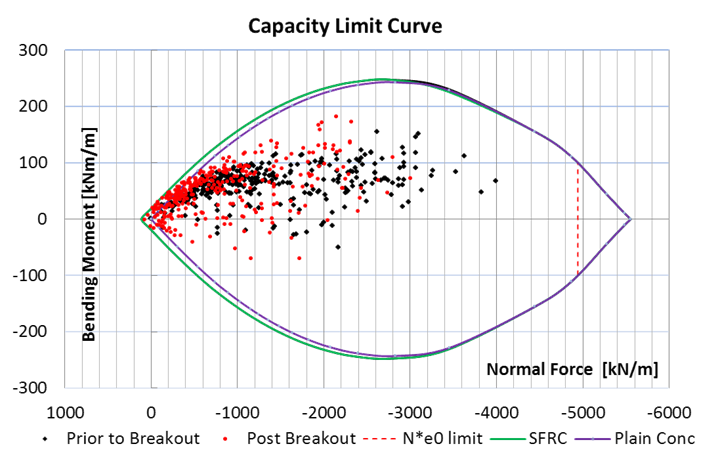
Figure 12 – Hoop Axial Force – Bending Moment interaction capacity limit curve for PL2RC after the passage of the westbound TBM.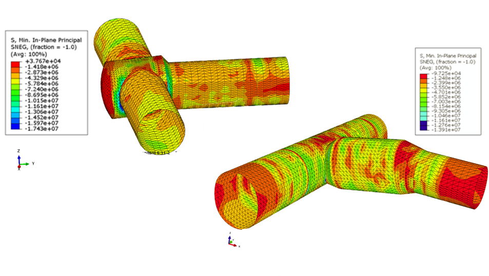
Figure 13 – Compressive stresses at the intrados in the PL2RC (top left) and CP1-CH1 (bottom right) FE model
Validation of the calculated deformations
In order to compare the accuracy of the predicted in-tunnel deformations, the results obtained from the actual monitoring arrays installed in PL2RC at TM 38.3m and in CP1-CH1 at TM 9.0m were compared with the FEA predictions. The prediction from the 3D FE model (based on the ko=0.6 models) was in good agreement with the observed in-tunnel deformations as shown in Figure 14.
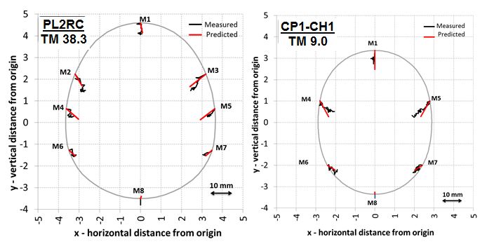
Figure 14 – Measured vs Predicted (3D FE model) deformations at TM 38.3m of PL2RC (left) and TM 9.0m of CP1-CH1 (right)
The induced ground surface settlements were also compared with the predictions from the FE model, although this was not within the scope of the design. The main surface assets were the Network Rail sidings and the Network Rail tracks, which were located above the alignment of PL2RC and CP1-CH1 respectively. The predictions were extracted from the ko=0.6 models.
Figure 15 illustrates the longitudinal settlement above the excavation of PL2RC and the transverse settlements above the excavation of CP1-CH1. Surface monitoring results above the two tunnels were only available from the readings on the Network Rail assets, hence the comparison had to follow this alignment. It is evident that the 3D FE model prediction produced a very close match with the observed settlements. On this basis, it can be seen that the FE modelling outputs provided excellent correlation to the observed behaviour, both in terms of in-tunnel deformation and surface movement.
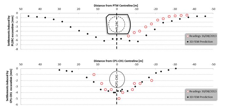
Figure 15 – Surface settlements induced by PL2RC excavation against measurements on the Network Rail sidings (top) and surface settlements induced by CP1-CH1 excavation against measurements on the Network Rail tracks (bottom).Conclusions
The alternative strategy devised by the BFK and DSP team proved to be a significant success, and provided the project with a reduction of 4 months on the programme and the avoidance of a significant amount of additional cost. This resulted in a major reduction in risk both in terms of programme and interface.
The design and independent category III checking was completed in time to support the Contractor’s construction programme. The solution provided the Contractor with a quick and easy method of forming the critical temporary connections; the wraparound structure was constructed in only two weeks at an average advance rate of 1.2 metres per day. The ability to run underground services and logistics through these temporary tunnels enabled the Contractor to safely undertake concurrent working of the Ticket Halls, SCL works and TBM works.
Non-linear finite element analyses (FEA) were carried out to support the design of the structures, assessing the SCL capacity and the interaction with the adjacent structures under various load cases, simulating the excavation steps in detail. The FEA modelling benefited from being able to use data from the project team’s “live” 3D geological model, updated in real time with all the available data from ground investigation and tunnel excavation, thus providing the designers with the best possible estimate of anticipated geology.
DSP have been able to deliver an innovative design, making use of advanced design tools resulting in an elegant, buildable, safe and efficient solution, requiring no mesh, no bar reinforcement and a thin shell of SFR shotcrete without any thickened zones around the openings. This was possible as the design team could react quickly to upcoming changes to the base design contract. The absence of steel bar reinforcement, coupled with the thin SCL shell, permitted the TBM to pass through the wraparound chamber rapidly, with no damage and without the need for personnel to work near an open face to fix reinforcement into the primary lining. The design also largely eliminated manual handling and working at height; this reduced the residual risk to an extremely low level.
Figure 16 shows the exposed TBM segments after the partial removal of the foam concrete in PL2Rc.
At the end, the final design was buildable and both tunnels successfully served their purpose. This model could be profitably applied on other projects to generate similar benefits for cost, programme, risk and health and safety.
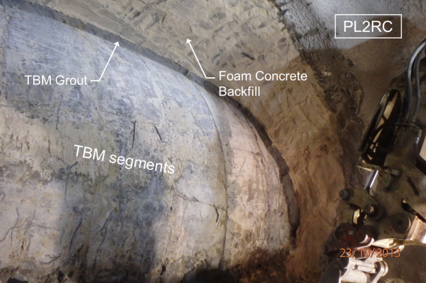
Figure 16 – Exposed TBM segments after partial removal of the foam concrete backfill in PL2RC.References
[1] Aldiss, D. T., Black, M. G., Entwisle, D. C., Page, D. P., & Terrington, R. L. (2012). Benefits of a 3D geological model for major tunnelling works: an example from Farringdon, east–central London, UK. Quarterly Journal of Engineering Geology and Hydrogeology, 45(4), 405-414.
[2] Crossrail C435 (2013). Design Statement for Temporary SCL Works. C435-BFK-C4-XST-M123-50001.
[3] Crossrail Standard CR-STD-303-2. Civil Engineering Design Standards – Part 2 (Tunnels and Shafts).
[4] Dassault Systemes Simulia 2011. ABAQUS Analysis User’s Manual-V6.12
[5] Gakis, A., Flynn, S. Nasekhian, A. 2014. Back analysis of observed measurements for optimised SCL tunnel design. NAT 2014
[6] Gakis, A., Salak, P. StJohn, A. 2014. Geotechnical Risk Management for Sprayed Concrete Lining Tunnels in Farringdon Crossrail Station. Proceedings of the World Tunnel Congress 2014 – Tunnels for a better Life. Foz do Iguaçu, Brazil.
[7] John, M., & Mattle, B. (2003). Shotcrete Lining Design: Factors of Influence. Proc. RETC.
[8] Poettler, R. (1990). Time-dependent rock—shotcrete interaction. A numerical shortcut. Computers and geotechnics, 9(3), 149-169.
[9] RILEM (2003). Final Recommendation of RILEM TC 162-TDF. Test and design methods for steel fibre reinforced concrete. Materials and Structures Vol 36, pp 560 – 567.
[10] Sauer, G., Gall, V., Bauer, E., and Dietmaier, P. 1994. Design of tunnel concrete linings using limit capacity curves. In: Siriwardane & Zaman (eds) Computer Methods and Advances in Geomechanics, Rotterdam. pp. 2621 – 2626. -
Authors

Angelos Gakis Dr. Dipl-Ing, MSc DIC, CEng MICE - Dr Sauer & Partners Ltd
Chief Geotechnical Engineer, Crossrail Farringdon Station
Petr Salak Eur Ing, MSc, CEng MICE - Dr Sauer & Partners Ltd
Design Manager, Dr. Sauer & Partners Ltd

Adrian St.John, BEng (Hons) Eur Ing FICE CEng - BAM Ferrovial Kier
Adrian St.John is a Fellow of the Institution of Civil Engineers and a Supervising Civil Engineer. He has spent most of his 24 year career working on major infrastructure and tunnelling projects in the UK and overseas, including the Brighton Stormwater tunnel and High Speed 1 at St Pancras. He spent 6 years as Chief Engineer for BFK Joint Venture who were the main contractor on Crossrail contracts C300, C410 and C435, and is the Design Director for Carillion Eiffage Kier (CEK) Joint Venture bidding for the forthcoming HS2 main civil works.
