The Design of Thermal Tunnel Energy Segments for Crossrail
Document
type: Technical Paper
Author:
Duncan P Nicholson BSc MSc DIC CEng MICE, Qing Chen BSc MSc FGS, Mike de Silva BSc PhD FCIWEM MIEEM CSci C.WEM, Alan Winter BSc MSc CEng MICE, Ralf Winterling MSc Dipl.-Ing, ICE Publishing
Publication
Date: 03/11/2014
-
Read the full document
I. Introduction
The shallow ground has a large potential of low enthalpy energy that can be used for heating and cooling purposes. With the advances in ground source heat pump technology it becomes increasingly feasible to capitalise on this geothermal energy present in the ground. The biggest advantage of the geothermal energy is that the soil temperature reaches a constant at a depth of approximately 10 to 15 m below surface. For example, in central London the soil temperature at 14 m below surface remains undisturbed at 14 °C. Outside London, the soil temperature is slightly lower.
Recent development has seen the use of foundation piles, diaphragm walls, and base slabs as ground heat exchangers (Adam and Markiewicz, 2009; Brandl et al, 2006; Fry, 2009). For example, thermal piles and walls involve attaching polymer absorber pipes to the reinforcement cages and this approach has been applied to Crossrail stations. Other application examples involving sprayed concrete linings include the tunnels at Stuttgart Metro U6 (Schneider, Moormann, 2010), Lainzer Tunnel (Franzius et al, 2011) and the metro stations (Brandl et al, 2010). Heat-exchange pipes have been placed along the lengths of the Channel Tunnel to extract heat from inside the tunnel (Personal communications).
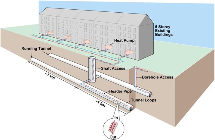
Figure 1: Schematic of the tunnel energy segment (TES) system
The paper by (Franzius and Pralle, 2011) discusses embedding plastic absorber pipes in the precast concrete tunnel segments of a conventional metro to collector heat from the adjacent ground. However, at Crossrail the primarily heat source is the waste heat rejected from trains and the secondary source is the surrounding ground. The heat is then transferred via header pipes to the ground surface, and then connected to heat pumps to supply the heat to buildings. Figure 1 shows the conceptual design of the Tunnel Energy Segment (TES) system.
II. Assessment of the heat inside tunnel
Operation of the London underground network over the past fifty years has gradually warmed the surrounding ground, which can no longer effectively absorb the waste heat from trains. The consequence is that today’s temperature in many underground lines remains high throughout the year, with temperatures of more than 30 °C in some parts of the network (Botelle et al, 2010). Increasing air temperature presents a big challenge to the underground train operators. In future climate change will exacerbate the current situation, with mean temperatures predicated to increase by 2 to 6 °C higher than normal within the next 40 years (Defra, 2012).
To start with, an assessment of the available heat energy inside tunnels was carried out. Train heat is emitted from the motors, air conditioning systems and brakes. This waste heat is injected inside the tunnel which warms the air and surrounding soil mass.
As seen in Table 1, at peak time there are 24 trains each hour on one direction, meaning one train per 2.5 minutes. The length of Crossrail tunnel is about 21 km long. Assuming the average train speed is 60 km/hr, a train will take 21 minutes to complete the journey. Hence, the number of trains in the tunnel at peak time is 21/2.5 = 8.4 trains.
Assuming one train motor generates on average of 1 MW net heat, this is focused on the tunnel length where the trains leaves the station. Its air-conditioning unit generates about 0.1 MW, the total heat output from 8.4 trains is 1.1 x 8.4 = 9.2 MW. Crossrail comprises about 42km of tunnels with a surface area at intrados is about 410,000 m2. Therefore, the peak heat input in terms of tunnel lining area is 9.2 x 10⁶ / 410,000 = 22 W per square metre of tunnel surface area. On a weekly basis, the average number of trains is 14 trains per hour. The average heat output is thus 22 x 14/24 = 13 W/m2. In addition, the ground behind the tunnel linings would also serve as a heat source similar to a closed-loop ground-source heat pump design. The train’s heat output also increases dramatically during braking as the train approaches the platform and accelerates away from the station. Therefore these sections have higher heat output and are the locations where TES should be focused. For comparison closed loop boreholes typically transfer 35 W/m run and small diameter foundation piles about 60 W per m run.
Based on the above simplified calculation, the base heat output from the tunnel was about 7 W/m2 base and the peak output was about 30 W/m2 peak. On this basis a 500 m length of tunnel would be able to support about 100 family apartments with a total heat demand of 1,200 MWh/yr which would be met by a combination of a 400 kW gas boiler and a 400 kW heat pump. The full network of Crossrail tunnels (2 No x 21 km tunnels) would comprise 84 such lengths and would consequently have the capacity to provide heat for 8,400 families (30,000 people) or equivalent building heating.
Table 1 Crossrail designed train frequency during normal operation (SP2)
From To Hours Train Freq No of Trains Monday – Friday 00:00 00:30 0.50 12 6 00:30 05:45 5.25 0 0 05:45 06:15 0.50 12 6 06:15 07:00 0.75 16 12 07:00 07:45 0.75 20 15 07:45 09:15 1.50 24 36 09:15 10:00 0.75 20 15 10:00 16:00 6.00 18 108 16:00 16:45 0.75 20 15 16:45 18:15 1.50 24 36 18:15 19:00 0.75 20 15 19:00 22:00 3.00 16 48 22:00 00:00 2.00 12 24 Total No. 336 Saturday 00:00 00:30 0.50 12 6 00:30 05:45 5.25 0 0 05:45 09:00 3.25 12 39 09:00 21:00 12.00 18 216 21:00 00:00 3.00 12 36 Total No. 297 Sunday 00:00 07:00 7.00 0 0 07:00 12:00 5.00 12 60 12:00 21:00 9.00 18 162 21:00 23:45 2.75 12 33 23:45 00:00 0.25 0 0 Total No. 255 III. Design of Tunnel Energy Segments system
-
Previous experience
There are a number of existing case studies on retrieving heat energy from tunnels. The Vienna LT22 testing plant was the first geothermally activated sprayed concrete lining tunnel in Austria. The absorber pipes were attached to a geosynthetic and placed between the primary and secondary tunnel lining (Adam and Markiewicz, 2009) followed by an installation in Germany at Stuttgart Metro U6, (Schneider and Moormann, 2010). More recently, the thermal activation of tunnel structures has been applied to TBM Tunnels. Züblin and REHAU have championed this development with a field test in the Katzenberg high-speed rail tunnel in Germany followed by the Jenbach twin track high-speed rail tunnel in Austria incorporated a 54 m long demonstration section with thermally activated segmental tunnel lining equipped with heat exchanger pipes. These pipes were connected to a heat pump in the utility centre building to provide hot water and space heating (Franzius and Pralle, 2011). It should be noted that the above schemes are taking heat from the ground mass rather than the tunnel air.
-
Crossrail experience
The Crossrail TES work built on this previous experience to help solve the very demanding technical and management challenges faced by the design team.
- Firstly, the TES design was started after the tunnel design had been completed and tendered. The TES design needed to cater for the absorber pipe requirements, whilst still meeting all the existing design requirements for structural, fire, H&V etc. For example, a design method had to be developed to enable the existing tunnel H&V design to be revised to incorporate the TES. The introduction of box out pockets at the ends of the segments to form pipe connection needed to take account of the caulking groove featured in the segment structural design.
- Secondly, discussions were held with the tunnel contractors to develop ways of incorporating the absorber pipes in segment moulds and ways of forming tunnel ring connections so that the TES did not delay construction or introduce high costs.
- Thirdly, TES needed to locate and manage a network of building who could use the heat.
- Fourthly the Crossrail Board needed to have design risk assessments and budget costs so that they could make informative decisions.
All these challenges need to be resolved to a demanding time frame. The multi-disciplinary inputs included tunneling, building services, structures, material, fire, geotechnics and hydrogeology, energy, hydraulics, costing, etc.
-
Thermal energy segments
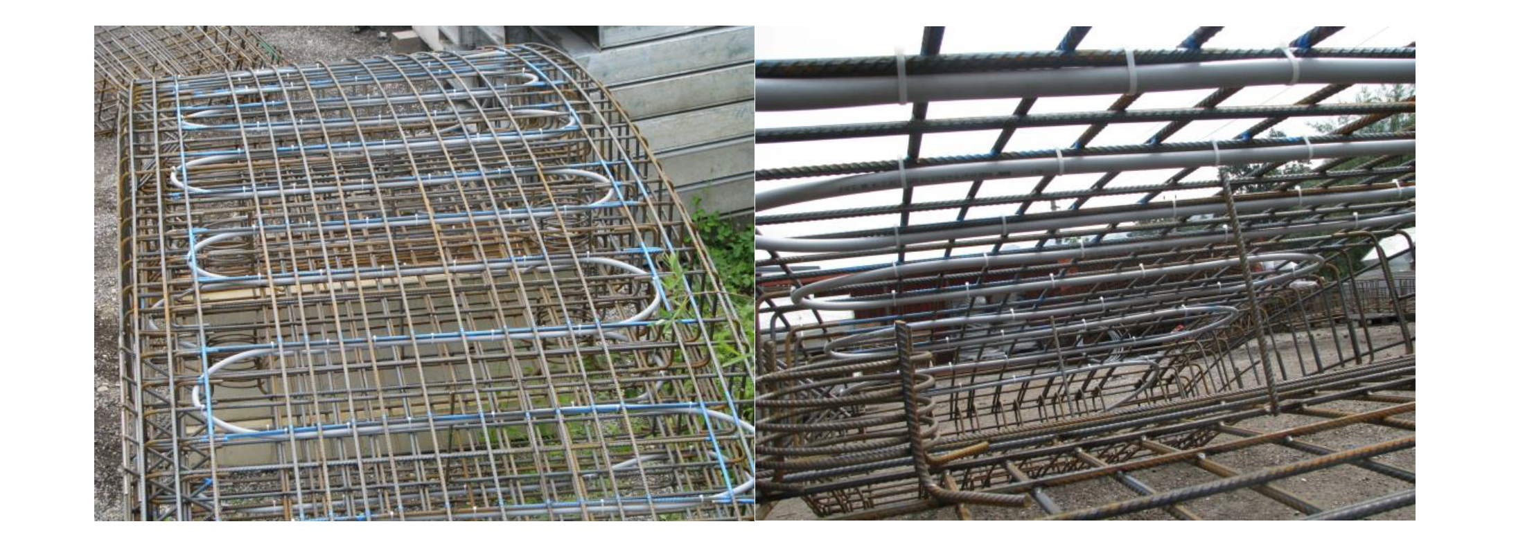
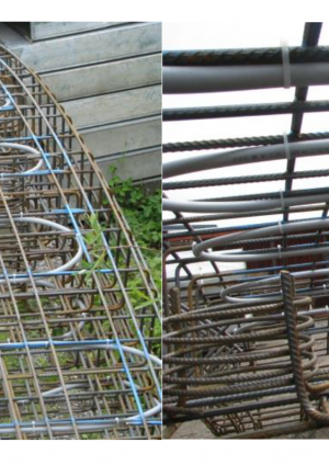
In order to extract heat from the tunnel, the concept design is to embed 20 mm internal diameter absorber pipes into conventional concrete segments before casting. The segments are fabricated using a standard segmental lining manufacturing process. The pipe lengths of 10 ~ 20 m are placed into each segment in a meandering fashion as shown in Figure 2. For the reinforced segments, the pipe can be tied to the cage or inserted on a separate support mesh. On Crossrail reinforced segments are used on the floating track sections. For fibre reinforced concrete segments, the pipes are softened in a hot water bath and then attached to a light cage which is then positioned inside the segment mould. To minimise fire damage, the pipes are placed at least 200 mm from the intrados. To meet minimum pipe bending radii a 300 mm pipe spacing has been adopted using the PE-Xa polymer pipe specification. Figure 2 shows a typical pipe arrangement for a segment with a reinforcement cage before concrete is poured.
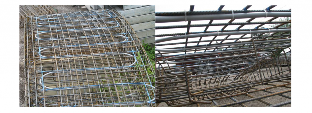
Figure 2: Absorber pipes assembled to a reinforcement segment before casting, Left – plane view, right – cross-section view (photos taken from Jenbach tunnel by Rehau Ltd)
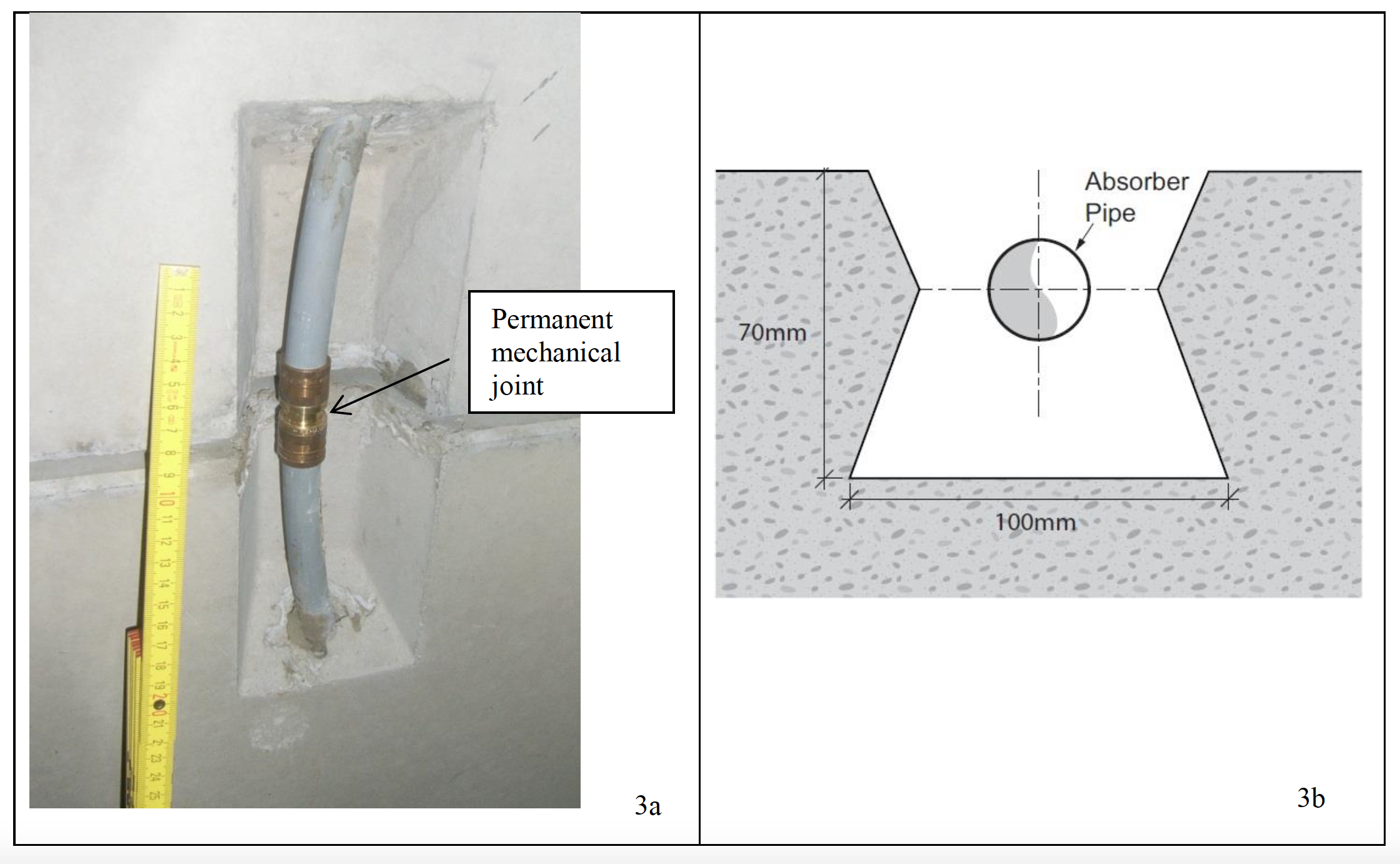
In order to form the connections between segments, box-outs are specially designed at the ends of segments. These pockets are about 200 mm long, 100 mm wide and 70 mm deep to allow a permanent mechanical coupling of the adjacent pipe-ends across the box-out, see Figure 3. The Crossrail box-outs have reverse tapers to retain the mortar filler.
The impact on structural integrity and fire safety induced by these changes to standard segment design are discussed later.
The pipe connections are formed immediately after the segment ring is erected at the tunnel face. The majority of work being carried out from the erection train towed behind the tunnel boring machine. The connection system was initially developed for thermally activated building structures (TABS)s in highrise buildings for pipe connections buried in the concrete structure. The system allows permanent mechanical connections (Everloc) to be rapidly made using PE-Xa pipe in a small space to reduce the installation time and have a robust and reliable connection. Once formed, these connections cannot be undone. The permanent couplings have been subjected to pressure tests and the results show that the polymer pipe fails before the joint, and this provides confidence in the integrity of the couplings.

Figure 3: Box-out for pipes’ radial joint at the end of segments. 3a – tapered box-out used in Jenbach tunnel; 3b – reversed tapered box-out design for TES
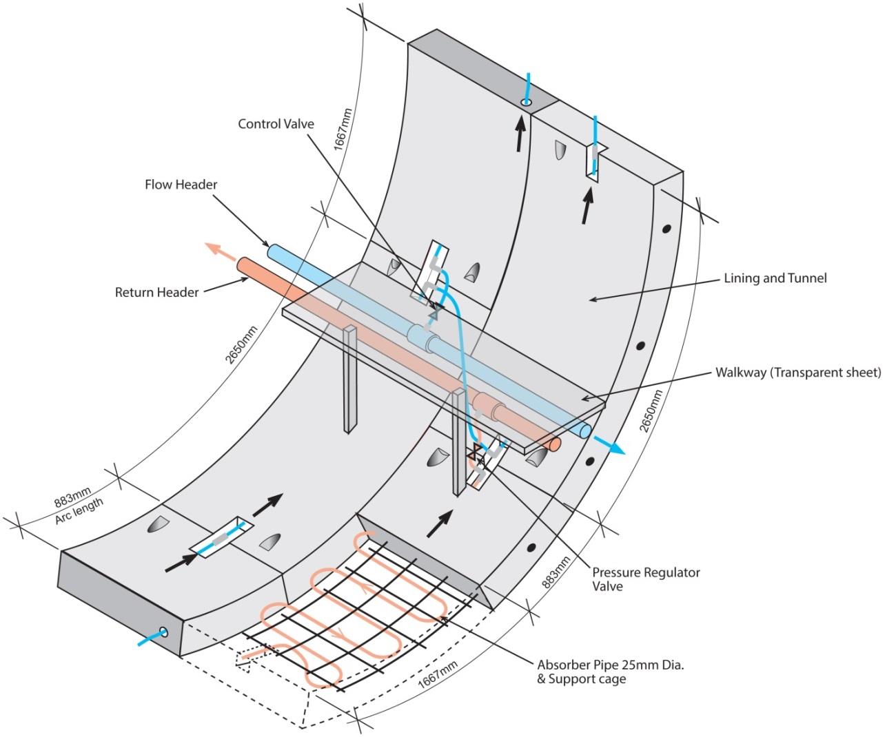
To form the complete circuitry, the absorber pipes need to be joined up to from a continuous ring of six segments. About 5 neighboring rings are connected to form a circuit, see Figure 4. Each circuit is connected to flow and return header pipes. Control valves are provided to isolate each circuit in the event of a local failure and to assist with de-airing. The ring to ring connection positions cannot be predetermined because each ring is slightly tapered. The orientation of the taper is selected during tunnel construction to steer the tunnel as the work progresses. Hence the ring to ring pipe connections are formed from short lengths of plastic polymer mounted on the tunnel surface, see Figure 5.
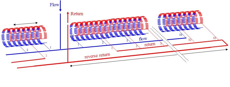
Figure 4: Schematic of pipework connections with three header pipes configuration.
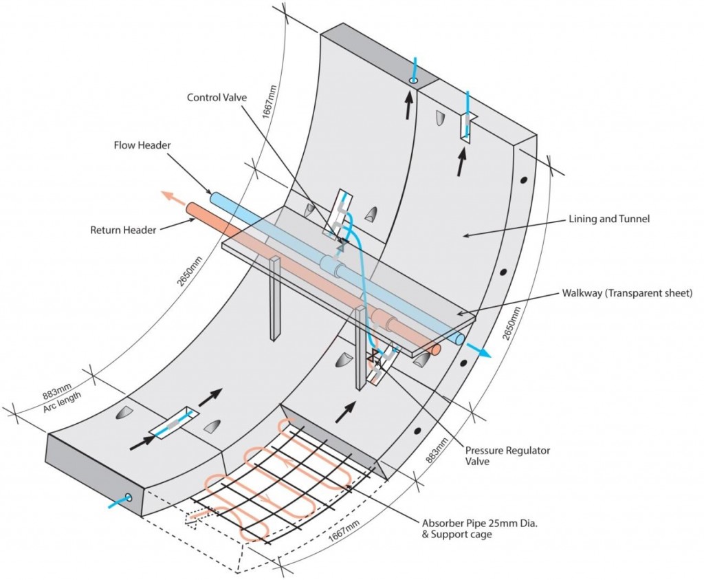
Figure 5: Schematic of TES design.
One complete circuit comprises about 11 m of pipe inside a standard segment and there are six segments plus a keystone in one ring. There are five rings in one circuit and 31 circuits to cover a tunnel length of about 250 m length. Tunnel header pipes would be connected to the surface though shafts and stations. Alternatively dedicated access boreholes could be provided at preferred surface locations for the header pipes, see Figure 1.
It has been planned that heat from the tunnels would be connected to district heating networks supplying heat energy to groups of buildings along the alignment of the tunnels. The income from the sale of heat to the district heating Energy Supply Companies (ESCos) provides a revenue stream to the tunnel operator which finances the installation and operation of the TES.
-
TES system design: Pipe work hydraulics and plant room.
The three header pipe “reverse return” arrangement was selected in preference to the two pipe arrangement because of the advantage of self-balancing. A procedure for removing trapped air was developed. Pressure losses were calculated for normal operation, and flushing of individual circuits and header pipes to remove trapped air bubbles.
Flow rate through the circuit varied depending on the heat extraction rate. The flow rates of 0.06 l/s achieved 10 W/m2 heat extraction rate and 0.12 l/s achieved 30 W/m2. The pressure losses for all fittings are calculated in accordance with CIBSE Guide C (CIBSE, 2007) except for the long radius U-bends that make up the meander of the pipes within the segments. The calculations for normal operations included a 50 kPa pressure drop for fittings on the circulation pump, and an additional pressure drop of 100 kPa for the heat exchanger. During flushing of air bubbles, the heat exchanger would be by-passed, so only 50 kPa pressure drop has been included in the calculations. The system is balanced using a reverse-return arrangement with valves on each circuit and an additional valve at the connections between the flow and return pipes. A schematic of the assumed layout is shown in Figure 5. A design margin of 15% is applied on the calculated pressure drop across the pipe network. The flow in the circuits needs to maintain turbulent state to ensure efficient heat exchange.
For normal operation header pipe lengths of 250 m were planned. Increasing the length to 500 m resulted in the system’s maximum pressure loss rising from 7.5 bar to 9.1 bar for 90 mm internal diameter header pipes.
To ensure the smooth running of the system, it needs to be flushed to remove any trapped air bubbles from the circuits. First, each circuit will be flushed individually. This procedure involves closing all valves, except one, leading to the circuits, and supply water to the system to get a minimum water flow velocity of 1.0 m/s in the loops, based on the recommendations of MIS 3005 Standard. Secondly, air is to be removed from the system by flushed the header pipe. The maximum pressure head loss is 8.3 bar for a 250 m long section, and 12.6 bar for a 500m section.
The header pipe length of between 250 m and 400 m on each side of an access point (e.g. shaft or borehole) was adopted to ensure the hydraulic performance could be maintained.
IV. Potential market for the heat
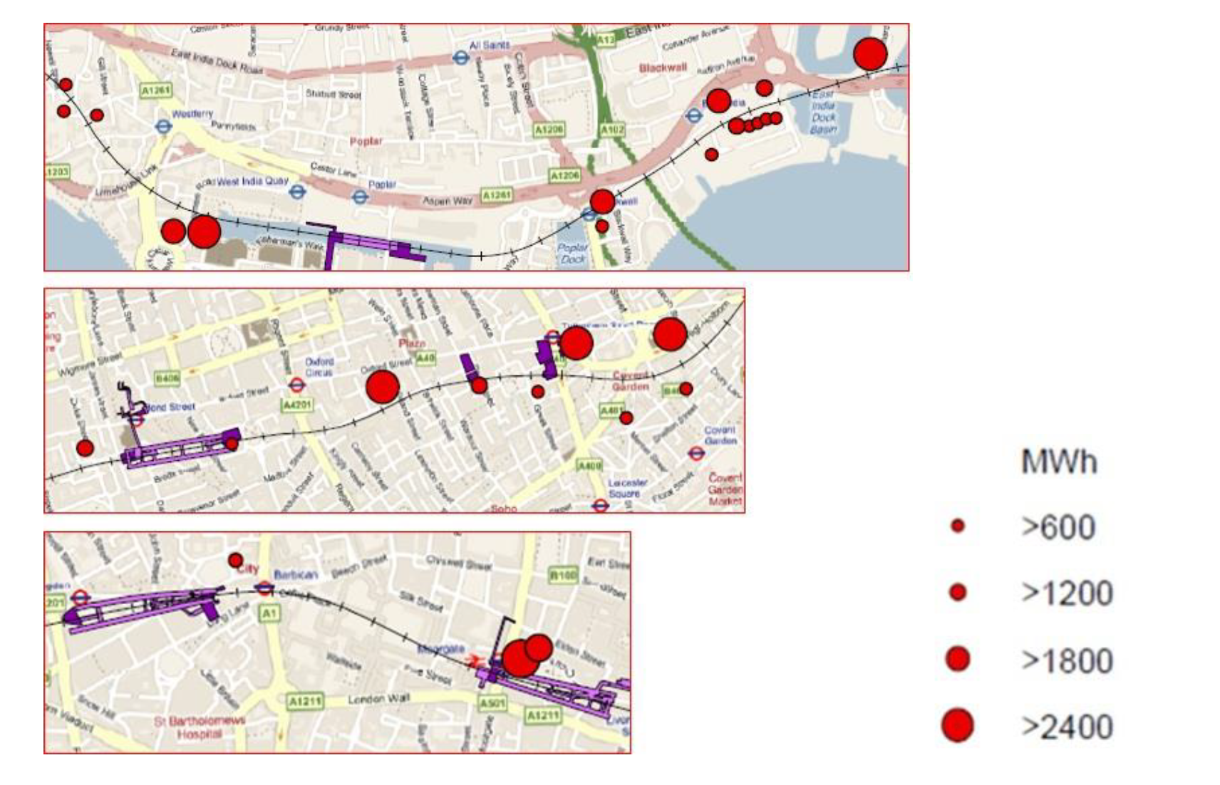
The London Heat Map and building inventory along the Crossrail alignment were used to establish adjacent buildings that could use the heat from the TES. These buildings were mapped in GIS. Two selection criteria were considered: Firstly, the buildings should have a sufficiently large heat demand to justify connection to the system. The minimum threshold of heat demand was based on the available heat from the tunnel, which is classified by annual heat demand of 600 MWh/yr, 1,200 MWh/yr, 1,800 MWh/yr and 2,400 MWh/yr. Secondly, by building type, the buildings should have a heat load profile which was complemented the efficient heat pump operation, i.e. relatively constant heating base load. These criteria were used to divide the buildings into tier 1 – most suitable buildings, tier 2 – moderate suitability and tier 3 -low suitability buildings.
Tier 1 – Hotels, Large Residential, Hospitals
Tier 2 – Schools, Higher Education, Public libraries, Museums
Tier 3 – Offices, Leisure Centres, Retail
As a result of this investigation 365 buildings with a heat load greater than 600 MWh/yr were identified within 100 m of the Crossrail Tunnel alignment. These buildings comprised 34 Nos Tier 1, 4 Nos Tier 2, and 327 Nos Tier 3 buildings. Some of these are shown in Figure 6.
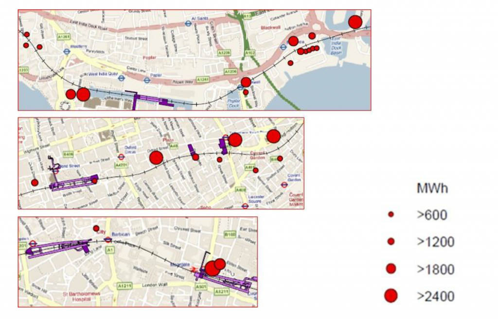
Figure 6: GIS study of existing energy users along Crossrail route: Tier 1 buildings at three locations – Canary Wharf, Bond Street, and Liverpool Street are shown as above.
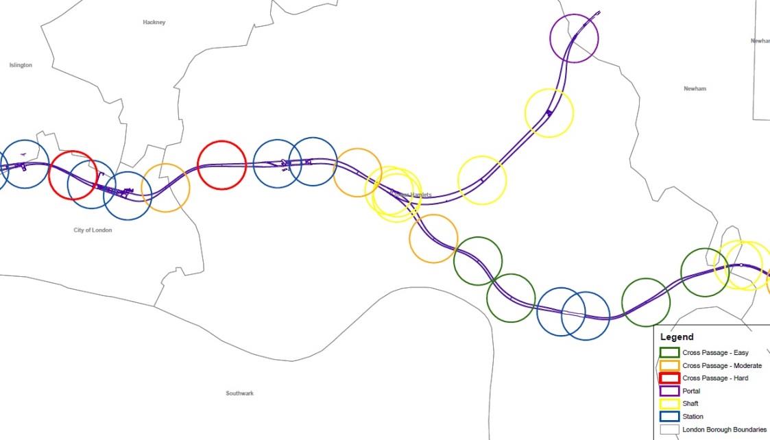
The technically feasible surface connection points based on shaft and tunnel access routes are shown on Figure 7. A 250 m diameter circle is shown for the standard connection header pipe length.
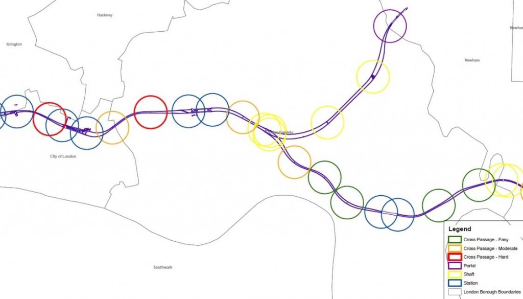
Figure 7: Analysis of surface connections. Each circle is of 250m radius, surface connection options are considered for shafts, cross-passages and directional drilled boreholes.
In some locations it was necessary to increase the capacity of the header pipes where the circles did not intersect. This approach enabled the energy segments to be connected to suitable buildings along the majority of the Crossrail tunnel.
V. Modelling of TES heat transfer
A finite-element numerical model was developed using numerical code LS-DYNA to simulate the thermal transfer behaviour of the TES, see Figure 8. The model is a 3-dimensional slice through the tunnel. In practice, the water in the pipe will be cooler near the inlet and warmer near the outlet; this model represents an average temperature along the length of the pipe. The analysis was carried out for 3 years without heat extraction in order to achieve a steady state condition within the soil. Heat was then extracted from the tunnel for a further 7 years to allow the system to change dynamically with varying tunnel temperature.
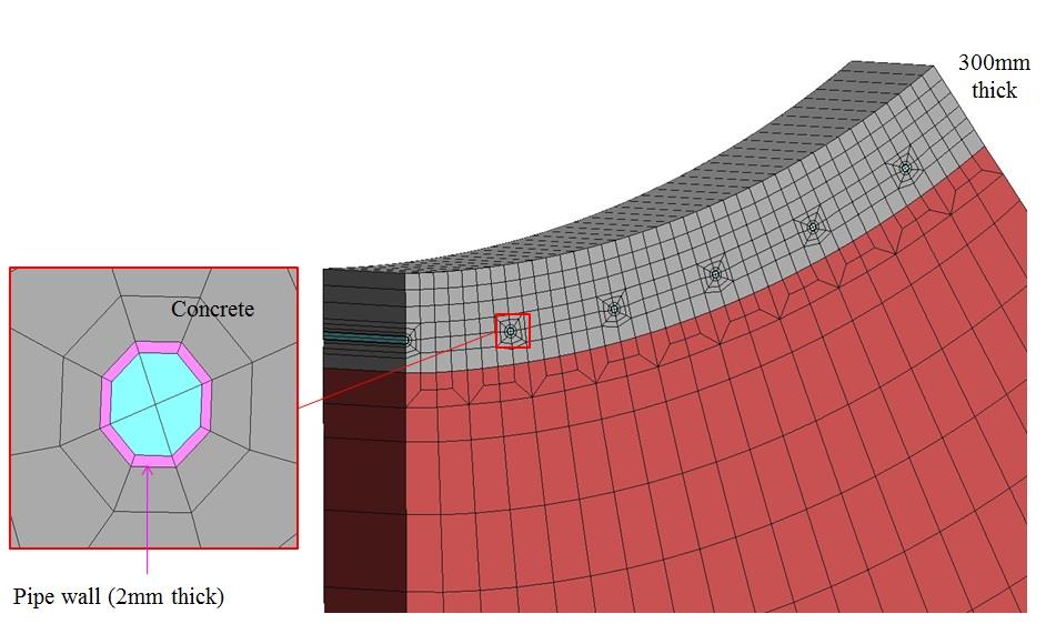
Figure 8: Set-up of the numerical thermal model in LS-DYNA to simulate heat transfer to absorber pipes
The thermal parameters used are summarised in Table 2. Furthermore, the boundary condition assumed an ambient soil temperature of 14.8°C at a distance of 100 m from the tunnel. Seasonal soil temperature variation was considered insignificant. In addition, the tunnel air temperature varies from 36°C in summer to 17°C in winter.
Table 2 Thermal parameters used in thermal analysis
Material Density
(kg/m3)
Conductivity (W/m.K) Heat Capacity (J/kg.K) Young’s Modulus
(kPa)
Soil 2,000 1.8 1,000 150,000 Concrete 2,500 1.33 750 31 x 106 Absorber pipe wall 1,000 0.087 1,000 100 Heat transfer coefficient from tunnel air to tunnel surface 5 W/m²K Sensitivity analysis was carried out for heat extraction rates ranging from 5 to 35 W/m2. The resulting fluid temperature inside pipes over time is shown in Figure 9. The system reaches quasi-steady state within the first year operation. To avoid freezing the pipes it was recommended that the continuous heat extraction rate be limited by 30 W/m2 in winter.
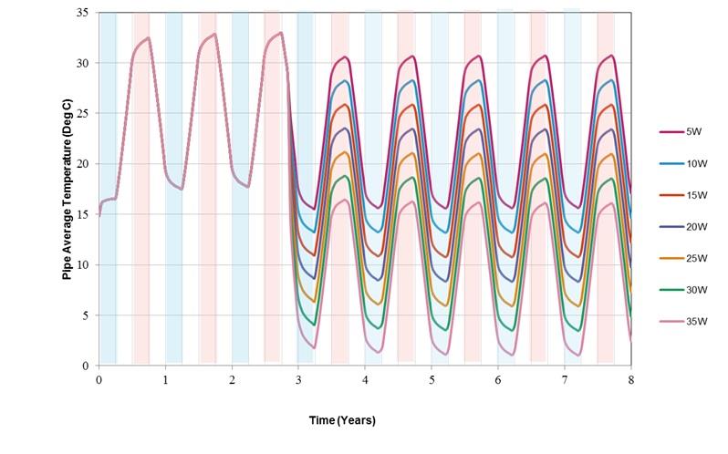
Figure 9: Predicated fluid temperature inside pipes over time for various extraction rates. Intital three years with no heat extraction.
VI. Tunnel cooling study
To understand the cooling effect of the TES inside the tunnel, a detailed 1-D ventilation model developed for the Crossrail tunnels was modified to include the TES, see Figure 10. The new model was validated by comparing the results with the LS DYNA analytical results.
Thermal simulations were carried out for the design full load train service pattern SP2 (240 m long trains, 24 TPH peak hour service frequency), with TES operating at a continuous predefined heat exchange rate.
The ventilation model predicts a reduction in peak tunnel air temperatures of 4 ºC (Dry Bulb, DB) with the pipework installed along the full length of the running tunnel when the flow rate was set to 7.44 l/s in order to achieve 10 W/m2 extraction rate, see Figure 11. Greater temperature reductions were achieved in areas such as tunnel east of Stepney Green junction. It was found that with the TES pipework installed in the proximity of the stations, the peak tunnel air temperature would be reduced up to 4 ºC DB when the flow rate was set higher to 14.88 l/s, ie 20 W/m2 extraction rate. This is due to focusing on the parts of the tunnel where braking and acceleration occurs.
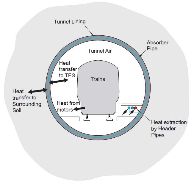
Figure 10: Set-up of the ventilation model showing heat transfer to tunnel and surrounding soil.
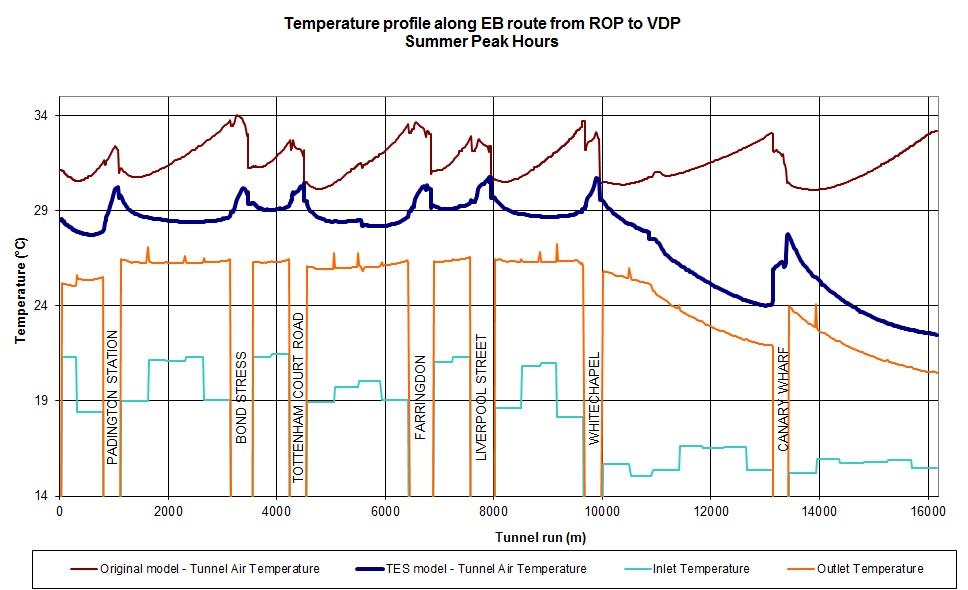
Figure 11: Predicated tunnel air temperature along Eastbound route from Royal Oak Portal to Canary Wharf Victoria Dock Portal during summer peak hours, with TES installed throughout the tunnel route. The absorber pipe inlet and outlet temperatures are also shown.
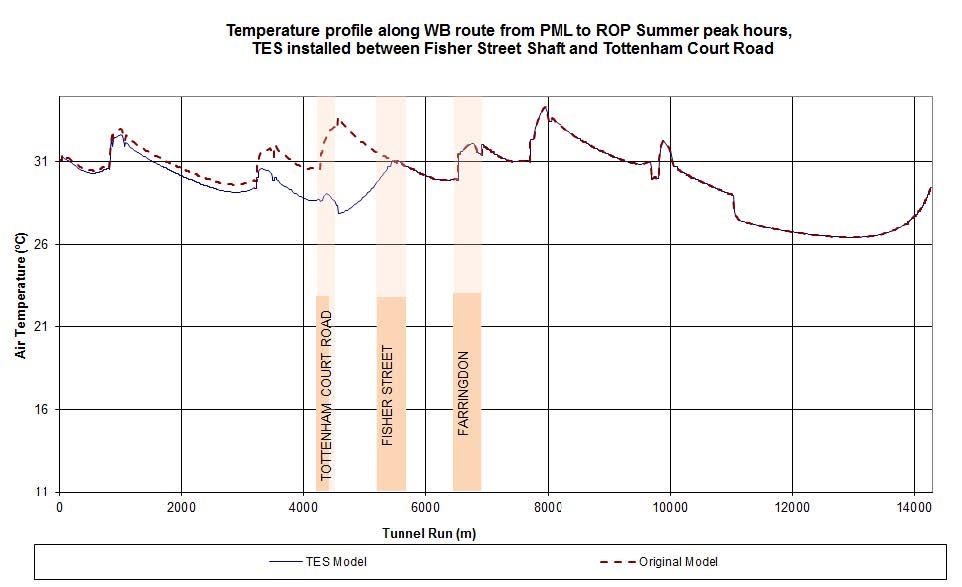
Figure 12: Predicated tunnel air temperature along Westbound route from Pudding Mill Lane Portal to Royal Oak Portal during summer peak hours, with TES installed between Fisher Street Shaft and Tottenham Court Road.
It should be noted that whenever the train heat inputs to the tunnels are lower than this full service pattern (for example in the early years of operation), lower heat extraction would be required to control water temperatures. This would have an impact on output from the heat pumps.
When the Crossrail system is operating, the bored tunnels are expected to be warmer than the surrounding ground due to waste heat emitted by the trains. Under the current design some of the heat is removed by air exchange through the draught relief ducts, and some by conduction through the tunnel walls to surrounding ground. TES will offer significant benefits as it will prevent a heat-build-up in the ground adjacent to the tunnel walls, and reduce the tunnel air temperature. This will lead to savings in the tunnel ventilation system operational cost and future proof the tunnel design for future increase in temperature due to climate change or higher train frequencies.
VII. Durability and operational considerations
-
Pipe durability
The PE-Xa grade pipe, comprising high-pressure cross-linked polyethylene, or equivalent, has been specified because:
- Tight pipe bending radii can be achieved.
- Robustness against notches, scratches and puncture loads during segment production and installation.
- Allows for segment joint extension at the box-outs.
- Permanent mechanical connections can be formed.
- Durability requirements in line with the tunnel design life (eg 120 years) at the pipe operating pressure and temperatures in accordance with EN 16892.
-
Thermal effects
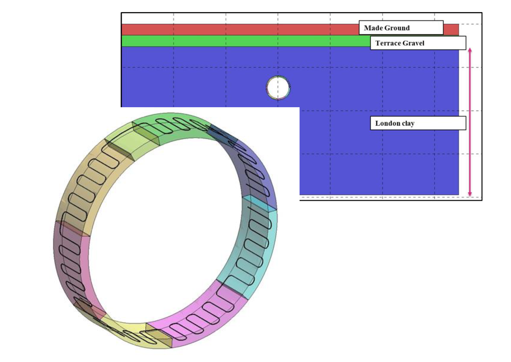
In order to understand the thermal effect on the tunnel structure, an additional finite element model was developed using LS-DYNA to represent the running tunnel with symmetry boundary conditions on the two vertical planes at right angles to the tunnel axis. The model is a 3-dimensional 1.6m slice through the tunnel with the absorber pipe, see Figure 13.

Figure 13: Set-up of the thermal-hydraulic-mechanical FE model for Crossrail tunnel linings in LS-DYNA. The black lines represent the absorber pipes.
The model using the elastic Mohr-Coulomb parameters, with the material properties summarised in Table 3. These soils were considered drained at all stages during the analysis. Their thermal properties used are given in Table 2. Thermal expansion coefficient of the soil skeleton and the pore fluid were assumed to be 3.0 x 10⁻⁵ / °C.
Table 3 Geotechnical parameters used in the LS-DYNA analysis
Stratigraphy Initial stress conditions Stiffness parameters Strength parameters Stratum γ (kN/m3) Ko
(top)
Ko
(base)
E’v
(top)
E’v
(base)
Poisson’s Ratio c’ (kPa) φp’ (°) cu (kPa) (top) cu (kPa) (base) Made Ground 18 0.5 0.5 10 10 0.2 0 25 – – River Terrace Deposits 18 0.5 0.5 25 25 0.25 0 40 – – London Clay 20 1.2 1.2 24 29 0.2 5 25 104 137 Lambeth Group 20 1 1 70 70 0.2 10 28 350 350 Thanet Sand 21 1 1 250 250 0.2 0 36 – – The thermal analyses were carried out for heat extraction rates from 0 (no heat extraction) to 30 W/m2. Under natural conditions (ie no heat extraction), the maximum computed tunnel diameter change is +1.1 mm in the summer and 1.6 mm in the winter. There is negligible deformation at crown and invert of the tunnel. At heat extraction of 30 W/m2 the tunnel shrinks at the axis level and expands at the crown during summer, and the tunnel shrinks towards the centre during winter. The changes in tunnel diameter are summarised in Table 4, 30 W/m2 extraction results in a further 1 mm deformation compared to the case of no heat extraction.
Table 4 Thermal effect on tunnel dimensions
Simulation stage Tunnel diameter change (mm) Crown-Invert Axis Level Summer (no extraction) +0.1 -1.1 Winter (no extraction) -0.5 -1.6 Summer (30 w/m2 heat extraction) +0.3 -1.9 Winter (30 w/m2 heat extraction) -0.6 -2.6 Hoop stress in the tunnel lining without thermal effects is 4 MPa at a depth of 16 m. Hand calculated hoop stress in the tunnel lining, assuming a depth of 16 m and soil density of 20 kN/m3, is approximately the same. As expected, the maximum hoop stress occurs at the convex to convex segmental joints. When no heat is extracted, the hoop stress (average through the segment thickness) shows a seasonal variation, being maximum in summer when it is 7% greater than the as-constructed condition. This rises by a further 2% when 30W/m2 heat extraction takes place. In winter, the average hoop stress is negligibly different from the as-constructed condition, whether heat is extracted or not. Although the heat extraction induces relatively large temperature gradient across the thickness of the segments, the hoop stresses at both surfaces are predicted to remain compressive.
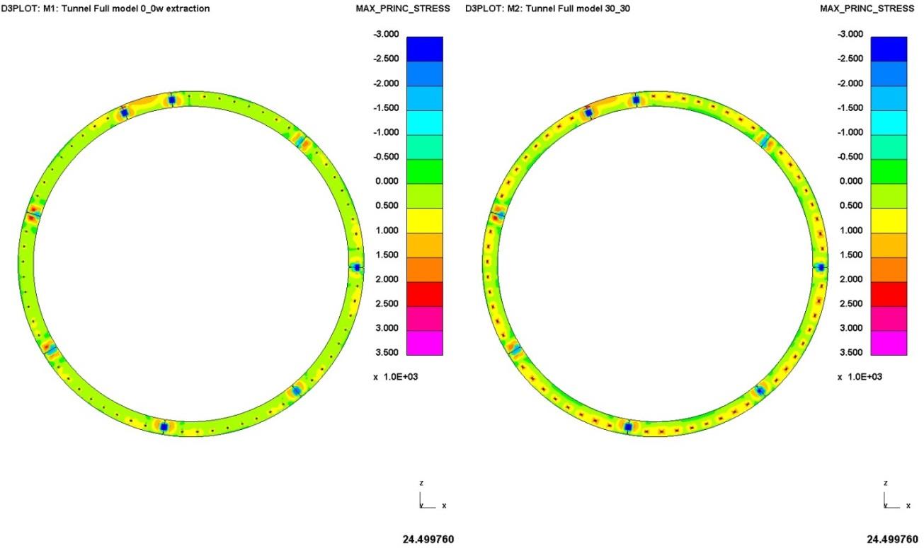
The computed tensile stress for no heat extraction and 30 W/m2 during summer and winter is shown in Figure 14. For the ground conditions and geometry adopted in the analysis, the computed maximum tensile (bursting) stress occurs at the convex to convex joints. It is likely that the tensile bursting stress will be proportional to the contact force at the joints, which in turn is proportional to the average hoop stress. Therefore it is assumed that the bursting stress will rise by 7% compared to the condition of no heat extraction, and by a further 2% if 30 W/m2 is extracted.

Figure 14: Comparison of maximum principal stress distribution in segments without and with heat extraction during summer
Tensile stress is also predicted around the pipes when heat is extracted, it reaches a maximum of 3.5 MPa when 30W/m2 is extracted, which is below the design tensile stress limit of 5.0 MPa.
-
Fire safety
The piping is made of cross-linked polyethylene (PE-Xa) which is a form of polymer comprising molecular chains made up of hydrogen and carbon atoms. Though the cross-linking process additional links are built between neighouring carbon atoms. The Crossrail Fire Safety Strategy for the Central Tunnels states that materials within the tunnels should be chosen based on the London Underground standard 1-085 Fire safety performance of materials. Section 5.6.1 of the Crossrail Tunnel Fire Safety Strategy states that:
“Any materials which do not comply with this standard will be risk-assessed to determine whether they are acceptable”.
The London Underground 1-085 standard has fire safety requirements for materials with regard to flammability, smoke emission, toxic fume emission. The proposed TES inclusion of exposed cross-linked polyethylene pipe with the tunnel is not fully compliant with the Standard in relation to flammability and potentially smoke emission. The Crossrail Fire Safety Strategy for the Central Tunnels allows a risk assessment to be carried out in lieu of strict compliance with the 1-085 Standard.
The embedded absorber piping is connected to a set of 3 header pipes, which are made of PE-Xa and 90 mm in diameter. To mitigate fire risk the design is based on burying the header pipes in mass concrete.
VIII. Operational and commercial benefits
It is important to assess the fundamental financial viability of the TES system. The elements to consider with respect to costs are initial capital tunneling cost, surface connection cost, cost incurred to connect the system to buildings, and operational cost.
The TES brings the following benefits to the tunnel operators:
-
Operational cost saving
Excess heat can cause operational difficulties. For example, metro tunnels may see a large heat input from trains, whereas power cables may raise the internal temperature of service tunnels. Therefore tunnel cooling often needs to be provided. The most cost-effective solution to achieve cooling would be natural ventilation, however this is rarely sufficient and conventionally fans are used to provide forced ventilation. Cooling the tunnel by means of the TES system will lead to saving in the operational cost of the ventilation fans. The heat capacity of the fluid in the absorber pipes embedded in the tunnel segments is much larger than air and hence allows for more efficient cooling than forced ventilation.
-
Capital cost saving
The physical size of the heat pumps may be significantly smaller than the air ventilation fans and associated air ducts that would normally be required for cooling the tunnel, hence allowing a more compact design and resulting in capital cost savings.
In some instances, using TES instead of forced air ventilation may even allow to reduce the tunnel diameter, where it is governed by the required air flow area. In a similar way, intermediate ventilation shafts may be downsized or removed because of the reduced air flow. In the future if these opportunities are exploited, significant capital cost savings may be achieved. At Crossrail the TES design options could not be developed fast enough to enable reduction in air ventilation and UPE usage to be incorporated into the design.
-
Carbon Saving
The provision of heat energy to buildings adjacent to tunnels reduces their heat requirement, for example the need for those buildings to heat air or water using conventional sources (gas, electricity, heating oil). On new construction work the TES heat could be used at the Planning stage as part of the Renewable Heat Incentive or the Part L renewable heating component. Accordingly, the use of TES provides a reduction in carbon output for the building being supplied with this heat energy. For example, 10 W/m2 tunnel heat extraction provides enough heat to supply continuous summer low temperature demand of 250 kW, and approximately 170 m3/day domestic hot water load preheat (approximately equivalent to a 500 bed luxury hotel), achieved carbon savings is about 42%.
-
Heat revenue
Selling the heat harvested from the tunnels to nearby properties will generate some direct income, in addition income may be possible through the renewable heat incentive and/or the selling of carbon offsets.
With the energy price rising and supply uncertainty, the TES may offer an alternative solution. Compared with geothermal piles and vertical borehole loops, the unit energy price is lower for TES system.
IX. Case Study: Fisher Street to Tottenham Court Road
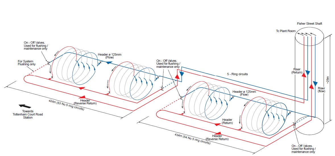
A case study design of 860 m long demonstration TES tunnel between Tottenham Court Road station and Fisher St Shaft was develop to a design for construction to show that all the technical issues could be addressed and costs could be quantified. In order to make full use of the tunnel length available the chosen tunnel was divided into two sections of about 430 m with two sets of header pipes coming in and out of the Fisher St Shaft, as shown in Figure 15.
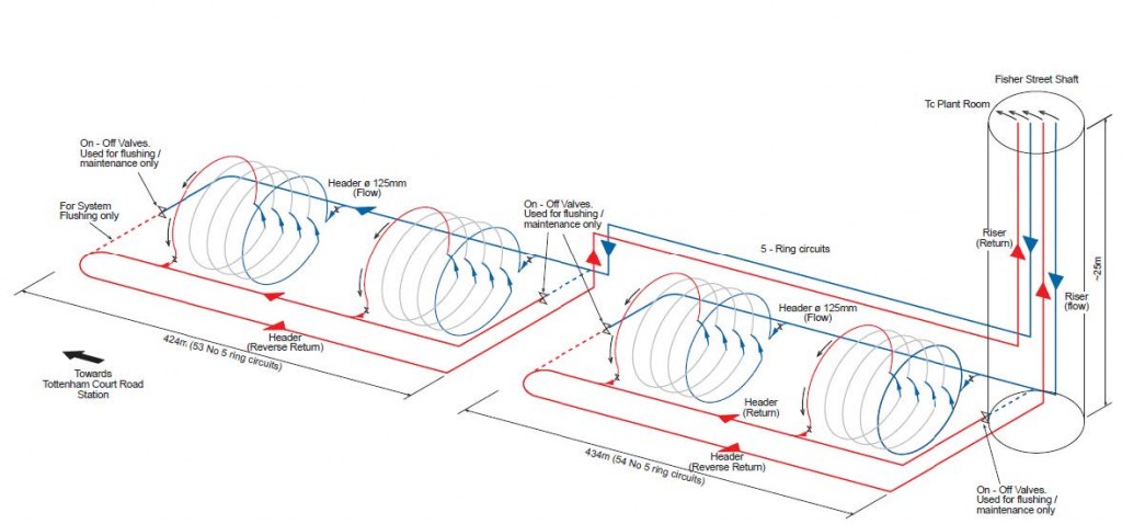
Figure 15: Schematic design of the TCR-FIS demonstration tunnel
The pressure drop at extraction rate of 30 W/m2 is calculated as 7.5 Bar during normal operation, and 10.3 Bar during flushing. The effect of the TES on the tunnel temperatures is illustrated in Figure 12. Due to the space limitations the plant room layout was modified to fit to an area of 4 m by 10 m. The plant room is to accommodate the primary circuit i.e. circulation and standby pumps, the secondary and tertiary circuit are located at the end-users premises.
In order to reduce the fire load, the headers are designed to be buried in mass concrete beneath the evacuation walkway. As a result, the fire load introduced by the TES over a 20 m length of tunnel duration 15 minutes is reduced to 375 kW, and this is 4.2% of the designed train fire load of 8.8 MW over 20m long carriage. Pure polyethylene complies with the LU material requirements in relation to toxic fume emissions.
The instrumentation and monitoring specifications were also developed both inside the tunnel and the plant room. The cost of the TES is relatively low compared to the tunnel construction budget.
The following technical issues have been addressed for the development of the demonstrator TES section:-
– An assessment of the local heat available from the trains and the soil.
– The development of the demonstrator section ventilation model which included TES.
– The TES and header pipe layouts to extract heat at Fisher Street shaft.
– The pipe layouts for the steel cage reinforced segments for the floating track slabs.
– The connection details between segments and rings and header pipes.
– The space proofing and plant room arrangements.
– The stress analysis for the thermal effects on tunnel linings
– The assessment of fire risks.
– The construction processes for the segment moulds and their tunnel erection.
– The assessment of surface buildings within 100m from the Crossrail route for heat use.
– The development of drawings, specifications, quantities and budget costs
X. Summary and Conclusion
This paper provides an overview of a tunnel energy segment (TES) system for Crossrail where heat is generated by the trains in the tunnels all year round. The system uses embedded closed-loop water filled pipework in tunnel segments to extract this heat. In this way it both cools the tunnels and provides heat for adjacent buildings. The water temperature supplied to the heat pumps is relatively high enabling the system to operate at higher coefficient of performance (COP) compared with conventional ground source heating systems.
A major challenge for the TES project was the coordination of the multidiscipline team to deliver the design and costing studies for the TES project.
The TES is a viable technology for the future “smart” cooling of tunnels; “smart” because it extracts heat in a form that can be utilised and with a potential revenue stream and because it can be used to reduce the reliance on UPE and tunnel ventilation systems, thus saving on electrical energy. These two benefits provide significant carbon and financial savings at a time where there is a focus on carbon reduction and when fuel costs are anticipated to increase between 50 ~100% decade on decade in real terms. The development of this technology on Crossrail provides a vital building block in understanding the benefits of the system such that it can be implemented at scale on future projects.
It is considered that the technical and commercial problems associated with the TES have been sufficiently addressed to warrant a demonstration tunnel to prove the system for use in future tunnels. Thinking one step ahead to future proofing during new metro design and construction is important.
The project receives the 2011 “Technical Innovation of the Year” by International Tunnelling Awards and the 2011 “Innovative use of Equipment” by Tunnel & Tunnelling International Awards.
XI. References
- CIBSE (2007) Guide C: Reference Data, 227p.
- Brandl, H., Adam, D., Markiewicz, R., Utenberger, W. and Hofinger, H. (2010). “Massivabsorbertechnologie zur Erdwarmenutzung bei der Wiener U-Bahnlinie U2,” Osterr. Ingenieur-und Architekten-Zeitschrift, Vol. 155, No 7-9 and 10-12, 1-7.
- Brandl, H. (2006). “Energy foundation and other thermo-active ground structures,” Géotechnique, Vol. 56. No. 2 81-122.
- Botelle, M., Payne, K., Redhead, B. (2010), Squeezing the heat out of London’s Tube, Proceedings of the ICE – Civil Engineering, Volume 163, Issue 3, 114 –122
- Adam, D. & Markiewicz, R. (2009). Energy from earth-coupled structures, foundations, tunnels and sewers, Géotechnique 59, No. 3, 229–236
- Fry, V.A. (2009) Lessons from London: regulation of open-loop ground source heat pumps in central London. Quarterly Journal of Engineering Geology and Hydrogeology 42 325-34.
- Franzius, J. N. and Pralle, N. (2011). “Turning segmental tunnels into sources of renewable energy.” Proceeding of ICE, Civil Engineering Vol. 164, 35-40.
- Schneider, M. and Moormann, C. (2010). “GeoTU6 – a geothermal research project for tunnels”, Tunnel 02/2010, pp 14-21.
-
-
Authors

Duncan P Nicholson BSc MSc DIC CEng MICE - Ove Arup and Partners Ltd
Director, Ove Arup and Partners Ltd
Qing Chen BSc MSc FGS - Ove Arup and Partners Ltd
Senior Hydrogeologist, Ove Arup and Partners Ltd

Mike de Silva BSc PhD FCIWEM MIEEM CSci C.WEM - Bechtel
Sustainability Manager
Mike has over 25 years of environmental and sustainability design and construction experience much of which has been gained in the rail industry. He has worked on the two largest rail link projects in the United Kingdom, Crossrail and High Speed 1. Mike worked as Sustainability Manager on the Crossrail between 2009 and 2017 and was responsible for delivering its sustainability strategy and reporting as well as leading on CEEQUAL and BREEAM project management, and had an assurance role on the management & measurement of the project’s carbon footprint. He is currently working on HS2 Phase 2b.
He is well known in the industry and has published a number of works including the well reviewed Royal Institute of Chartered Surveyors publication “Sustainability & the Property Lifecycle”. He has also sat on a number of working groups including CEEQUAL International, BREEAM Infrastructure and BES6001 a voluntary standard on responsible sourcing of construction materials & products, and is currently on the editorial panel for the ICE Journal, Engineering Sustainability.
Alan Winter BSc MSc CEng MICE - Crossrail Ltd
Bored Tunnel Engineer, Crossrail Ltd
Ralf Winterling MSc Dipl.-Ing - Rehau AG+Co
Technical Manager, Rehau AG+Co, Germany