Transporting Tunnel Boring Machines
Document
type: Technical Paper
Author:
Chris Hickman MEng, ICE Publishing
Publication
Date: 03/11/2014
-
Read the full document
1 Introduction
As the world population grows our infrastructure needs increase but the space available for new development becomes scarcer. In our cities we look to push new infrastructure requirements below ground and we strive to provide faster and more efficient transport links. Examples of such projects in the UK include Crossrail and High Speed 2. To help deliver these projects the UK tunnelling industry is in resurgence and engineers are developing new technologies and construction methods to speed delivery, increase efficiency and reduce costs. Bearing in mind the increasing need for tunnels it is reasonable to assume that more TBM transits may be required in the UK before long. In developing transit methods it is always useful to draw on the experience of others who have carried out similar tasks.
TBM transits are rare but have been made possible in recent years by innovative thinking and technological advances in heavy lifting equipment. The task of moving a TBM whole is a complex procedure, carrying with it significant cost and risk implications, and therefore it is avoided in most circumstances. However, examples where a TBM transit may be considered include cases where space restrictions mean that the TBM cannot be assembled in launch position, transits through pre‐ formed caverns such as platform tunnels and on projects where a series of tunnels are required with relatively short gaps between tunnels.
This report aims to highlight the options available for transporting TBMs whole and highlight the advantages of each option. To provide a tangible example, the report draws on the experience of the engineers working on the Crossrail Western Running Tunnels project. Examples include the transportation of two 1200 tonne, 140 m long TBMs from the assembly area at Westbourne Park, 600 m down to the launch chamber at Royal Oak Portal and the options being developed for the TBM transit at Bond Street Station. The report also looks at options used on a number of other recent tunnelling projects across Europe including the Prague Metro Line Extension, Barcelona Line 9 and the Biel Bypass. It is hoped that this information can be used to help develop faster and more efficient transit methods but also highlight issues that can be avoided at design stage.
2 Summary
2.1 TBM Transit Options
2.1.1 Continuous Cradles
The most common method of transporting a TBM whole is with the use of a continuous cradle. It is a continuous support structure installed for the entire length of the transit. The cradle structure is often formed of either a steel frame or a concrete invert slab profiled to suit the TBM with continuous rails cast into the surface.
An example of a continuous steel cradle is shown in Figure 1 below. In order to propel the TBM forward typically a steel beam will be fixed behind to the steel cradle. The propulsion rams in the shield can then be used to push against this beam and move forward. When the rams have reached their full extension the beam can be removed and moved forward and the process is repeated.
The backup gantries are ordinarily supported on inclined bogies running in the tunnel lining. However, in the example shown below no tunnel lining has been constructed and therefore the backup gantries are transferred onto a separate system of bogies running on tracks installed in the cradle.
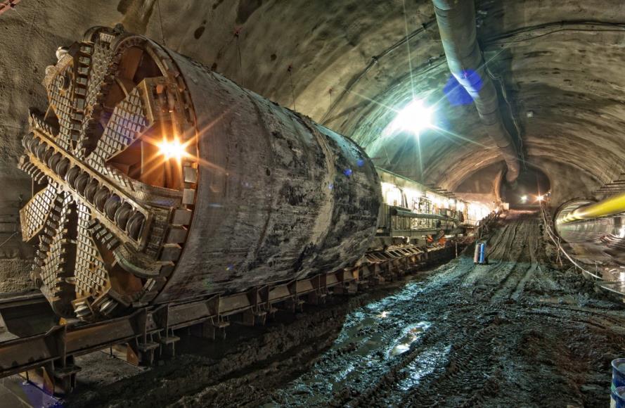
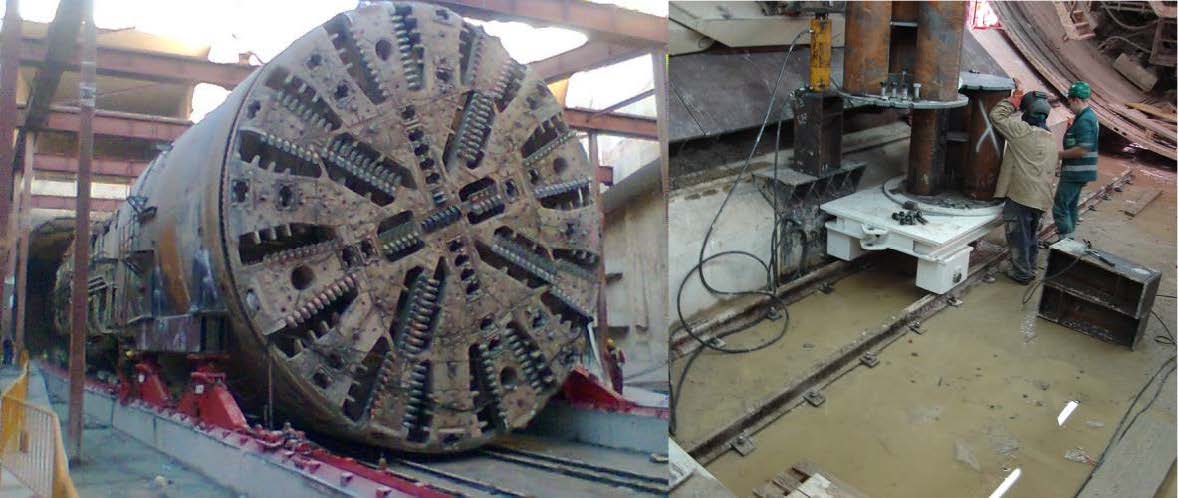
Figure 1 ‐ Prague Metro Line Extension ‐ Cerveny Vrch Station – Showing a TBM transiting through a preformed station cavern on a continuous steel cradle [Stehlik, E, 2011]
In the case of continuous concrete cradles the TBM can be propelled forward by laying invert segments behind the TBM and shove against these. The gap between the concrete slab and the invert segments is packed and then later grouted in place to provide a stable structure to support the backup gantries. The arrangement has the advantage of being relatively simple and the number of invert segments can be selected to suit the inclination of the bogies and therefore, the backup train can continue uninterrupted. In addition to this advantage, if a temporary rail system is used to service tunnelling works the rail for the tunnel locos can be laid as it would be in the tunnel behind. This means that the advancement of the TBM and the supply of materials remain relatively free of disruption. Figures 2 and 3 below illustrate the arrangement in more detail.
Figure 2 ‐ Prague Metro Line Extension ‐ Petriny Station – Showing a continuous concrete invert slab with steel profiles cast into the surface [Stehlik, E, 2011]
Figure 3 ‐ Prague Metro Line Extension ‐ Petriny Station – Showing invert segments laid to propel the TBM forward and support the backup gantries [Stehlik, E, 2011]
Due to the significant amount of material required to construct a continuous cradle, TBM transits using these methods are generally restricted to transits along the tunnel route and are not more than a couple of hundred metres in length. As the transit length increases the cost of materials will increase and a point will be reached whereby alternative options are considered to provide savings. The solution is however, ideal for openings on the tunnel route such as platform tunnels where other considerations may offset the installation costs. The considerations include access for materials and equipment for transiting the TBMs as well as a need to minimise disruption to tunnelling activities and therefore, a fast and efficient transit method is required.
2.1.2 Mobile Cradles
In circumstances where a longer transit is required, alternative methods are generally considered to be more cost effective. Examples where TBMs have been transited out in the open are rare but have become more common in recent years. Arrangements generally involve a short cradle structure or frame welded to the TBM shield. The purpose of the frame is to provide a surface onto which hydraulic jacks can lift the shield section of the TBM. Propulsion is then provided by either push‐pull jacks running in skid tracks or a SPMT. A separate arrangement is then used to support the TBM backup train. To provide more detail three examples of projects where TBMs have been transported using a mobile cradle system are considered in the following section.
2.2 Case Studies
2.2.1 Barcelona Line 9, Pozo de Sagrera, Open Shaft Crossing
In 2007, engineers started looking at options to transit a 12.06 m diameter, 11.75 m long, 1500 tonne TBM shield and a further 1000 tonnes of backup gantries without the need to disassemble the machine from its backup. The transit length was 80 m though an open shaft with two curves with a radius of 285 and 300 m respectively.
Engineers adopted a standard skidding system incorporating hydraulic skid shoes with a stainless steel base running in steel skid tracks lined with PTFE pads to reduce friction. Four skidding shoes were employed for the task each with a vertical lift capacity of 500 tonnes. Two brackets were welded to the TBM shield with a beam below transferring the load of the machine onto the vertical jacks. Propulsion was provided by four hydraulic rams operating in the skid tracks. These operated with an extend and contract sequence intermittently locking to the skid track and moving the TBM (push‐pull jacks). The horizontal thrust capacity of the rams was 64 tonnes and the pull capacity of 34 tonnes and a 620 mm stroke. All four jacks work together with two pushing and two pulling thus a total thrust force of 196 tonnes at any one time. The arrangement is illustrated in figure 4 below.
Figure 4 – Barcelona Line 9 ‐ Detail showing TBM shield jacking arrangement [ALE, 2007]
In order to allow the TBM to pass through the curves in the transit route the skid tracks were laid out and fixed into place prior to the arrival of the TBM. To allow the rigid TBM Shield to pass through the tight curves each vertical jack was fitted with a swivel head arrangement to allow movement in both the longitudinal and transverse axis.
In order to support and transit the TBM backups engineers developed a special device to allow the backups to run on rails. The system comprised of legs extending from the underside of the backups to a special bogie car running on a pair of rails as shown in figure 5 below. The arrangement allowed the backup train to pass through the tight curves.

Figure 5 – Barcelona Line 9 ‐ TBM shield traveling through shaft using skid shoes (right) and bogies for backup gantries running on rails (left) [ALE, 2007]
Once the TBM had reached the final position, the machine was lowered by vertical jacks onto concrete supports ready for re‐launch. As the TBM advanced back into the newly constructed tunnel the bogie cars supporting the backup gantries were progressively removed. The whole transit operation was completed in eight days thus advancing at an average rate of 8 m/h.
2.2.2 Switzerland, Biel Bypass, Transit between Tunnels
As part of the construction of a new ring road in Switzerland several tunnels were required to allow the road to pass through the areas with steep and challenging topography. The spacing between each tunnel was very short and therefore, engineers chose to transport the TBM whole between tunnels rather than dismantling, transporting and re‐assembling the TBM. The first of the two transits was considered to be the most complex and involved transiting the 12.56 m diameter, 110 m long, 2500 tonne machine 625 m between tunnels.
On route to the re‐launch position an existing road bridge had to be lifted and the full length of the TBM had to pass in a 24 hour window to allow the bridge to re‐open to reduce the impact on traffic. The TBM transit system therefore, had to be designed to allow the TBM to clear the bridge with time to carry out the bridge lifting and re‐opening operations.
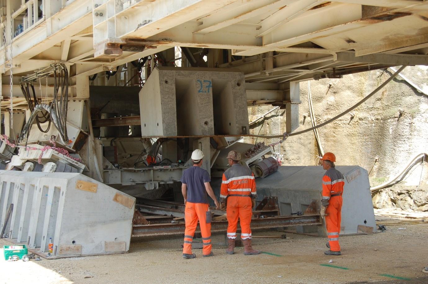
In a similar way to the system used in Barcelona, a lifting frame was welded to the side of the shield with four 500 tonne skid shoes lifting the TBM shield and providing a low friction surface on which to skid the TBM. However, unlike the case in Barcelona the transit route included a 2.5 % incline followed by a 3.7 % decline to the start of the next tunnel. Twelve 40 tonne strand jacks were used to haul the machine uphill and a further four stand jacks were used to provide restraint to the TBM on its route downhill. The moving procedure involved jacking the TBM up using the skid shoes, dragging it forward and setting it down again. Each cycle moved the TBM 4 m and an average speed of 7 m/h was achieved. The arrangement is shown in figure 6 below and illustrates the sheer scale of this operation.
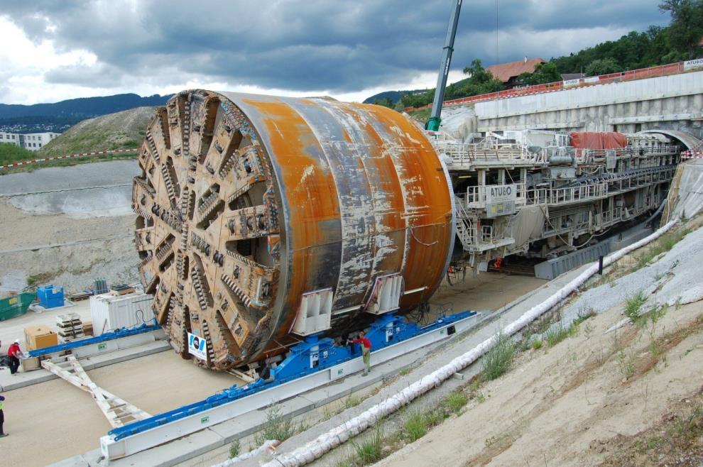
Figure 6 ‐ Biel Bypass – TBM shield supported on skid shoes transited using strand jacks with backup gantries running on concrete blocks [Thomas, I, 2011]
Unlike the bogie system used in Barcelona engineers chose to use the same inclined wheels which run in the tunnel lining. This involved developing a new system of pre‐cast concrete blocks for the bogies to run on when they had left the tunnel. The concrete blocks came in sections and were lifted into place under the bridge (behind the shield and before the first backup). In order to minimise the number of blocks required only enough blocks to cover the length of the backup train were produced. As the TBM advanced, the last of the concrete bocks was removed and placed in front of the TBM. The system is illustrated in figure 7 below.
The restricting factor to the rate of movement was found to be the rate at which workers could carry the concrete blocks through the backup train and position them in place behind the TBM shield.
Despite this restriction successful transits were carried out in 2010 and 2011.

Figure 7‐ Biel Bypass – TBM laying concrete blocks for backup gantry support [Thomas, I, 2011]
2.2.3 Crossrail, Transit from Westbourne Park to Royal Oak Portal
In 2011 engineers working on the Crossrail Western Running Tunnels contract started looking into options to transit two TBMs whole from the assembly area at Westbourne Park (WBP) to the launch chamber 600 m away at Royal Oak Portal. Each TBM shield was 7.1 m in diameter, 12.5 m long and weighed 600 tonnes with the backup gantries adding a further 140 m to the length and an additional 500 tonnes. A number of obstacles were present on the transit route including curves with a radius of 200 m, multiple underground structures, a bridge, a 3.3 % decline, reduced headroom under permanent props in the launch chamber and a 1.7 m step. The transit method had to be selected to best tackle each of these obstacles whilst reducing disruption, risk and costs.
The existing footbridge located on the transit route was used by school children and commuters to cross the construction site, London Underground lines and Network Rail lines. Due to height restrictions the bridge had to be raised around 4 m to allow the shield to pass underneath. Regular use of the bridge by the public meant Westminster City Council (the local authority) was keen to minimise disruption to the public and therefore, the transit solution selected should allow the TBM to clear the bridge as quick as reasonably practical.
Two transit options were considered for transporting the TBMs; these included the skidding arrangement discussed in the examples from Barcelona and Switzerland and the use of SPMTs. The skidding options promised advance rates of 12 m/h for the straight sections reducing to 6 m/h for curves. The SPMT option offered a significantly faster rate of up to 6 km/hr. The cost of hiring SPMTs is higher than skidding equipment however, due to the increased speed and the reduced manpower requirements of this option, quotations from various heavy lifting specialists show that in this case the cost difference between each option was not significantly different. Due to the time pressures of clearing Hampden Street Footbridge and the small difference in cost between options SPMTs were chosen for the first section of the transit route. This allowed engineers to raise the bridge, transit the TBM through, lower the bridge and re‐open the bridge within a 24 hour window.
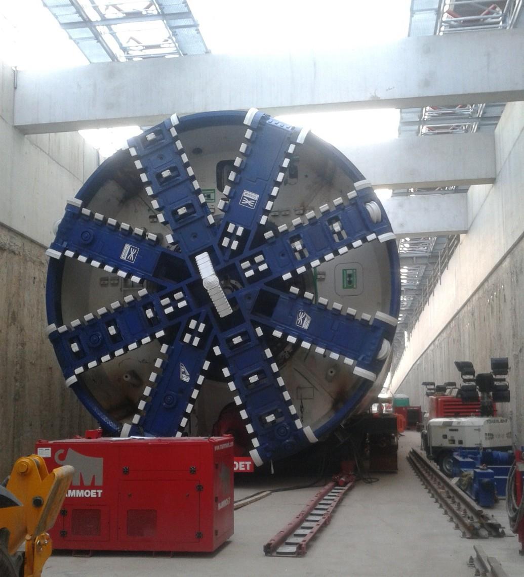
In order to lift the TBM onto the SPMT for transport it was jacked up on a cradle structure using four 200 tonne climbing jacks to a height of 1.5 m. The SPMT was then maneuvered into position below the cradle before lowering the TBM into place. The arrangement used is shown in figure 8 below.
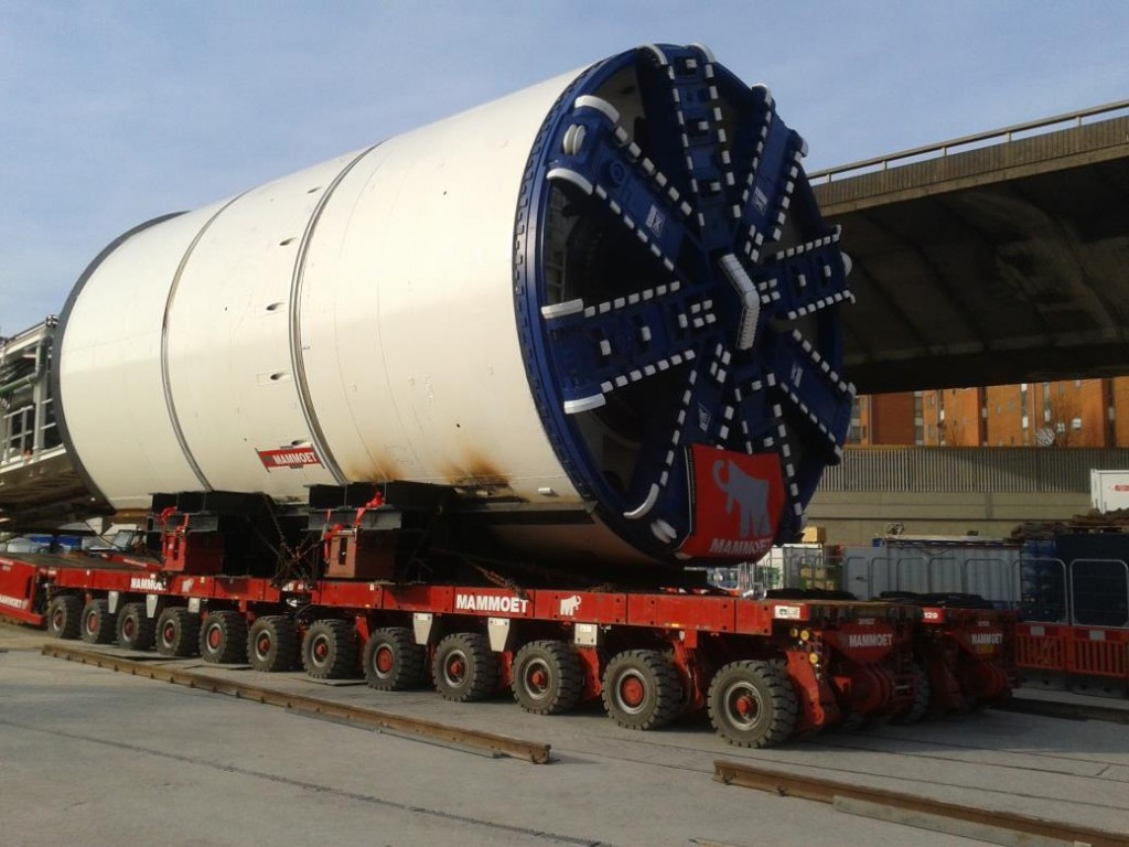
Figure 8 – Crossrail Western Running Tunnels – TBM shield supported on cradle structure transported on SPMT [Hickman, C, 2012]
In addition to time constraints, engineers also had to consider the capacity of the substructure and assets below to withstand the load of the TBM as it passed. The site information and ground investigation report highlighted a brick sewer and pumping chamber and a series of soft spots in the foundation soil. The design of the SPMTs was selected to both have capacity to support the TBM whilst also to sufficiently spreading the load onto the ground below. For this purpose a system incorporating two rows of twelve axles spread the load such that a ground bearing pressure of 8.7 tonnes/m2 was exerted on the ground.
The backups were transited using fixed wheels running on a rail system similar to that used on the Barcelona Line 9 project. So that the SPMTs did not run over the rail, the rail was laid in 12 m sections behind the TBM shield and before the first backup gantry. Figure 9 below shows the backup train transport system as the TBM approaches the launch chamber.
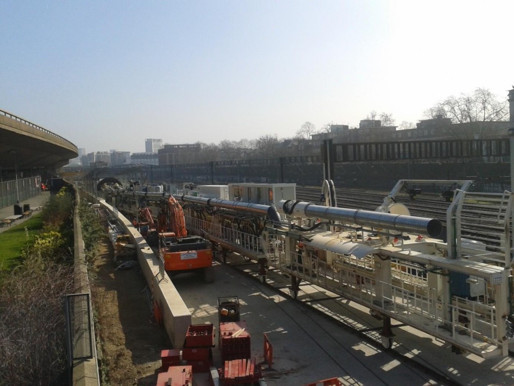
Figure 9 – Crossrail Western Running Tunnels – TBM backups transported on a bogie and rail system [Hickman, C, 2012]
The system was successful on the straight sections of the transit route but issues arose as the TBM passed through the 200 m radii on the route. The problems were caused by lateral loads exerted on the fixed wheels as the TBM passed through these curves. Whilst the loads in question were small, a lack of suitable locations to install the wheels meant that several were welded to sections without stiffeners and bracing. The un‐braced nature of the fixing locations meant that buckling of the supporting members occurred and alternative support methods had to be adopted in these locations. In hindsight, it would have been wise to remove the inclined bogies and replace them with the fixed wheels at these locations until the TBM was in launch position.
After passing the footbridge, the TBM descended down a 3.3 % gradient to the launch chamber. The structure of the launch chamber included a series of low level props. The lowest of the props was 7.45 m above the level of the baseslab and, as the TBM shield had a diameter of 7.1 m this left little room for the cradle structure and transport equipment. Therefore, in order to pass under the props the TBM had to be transferred onto skidding equipment for the final 100m of the transit.
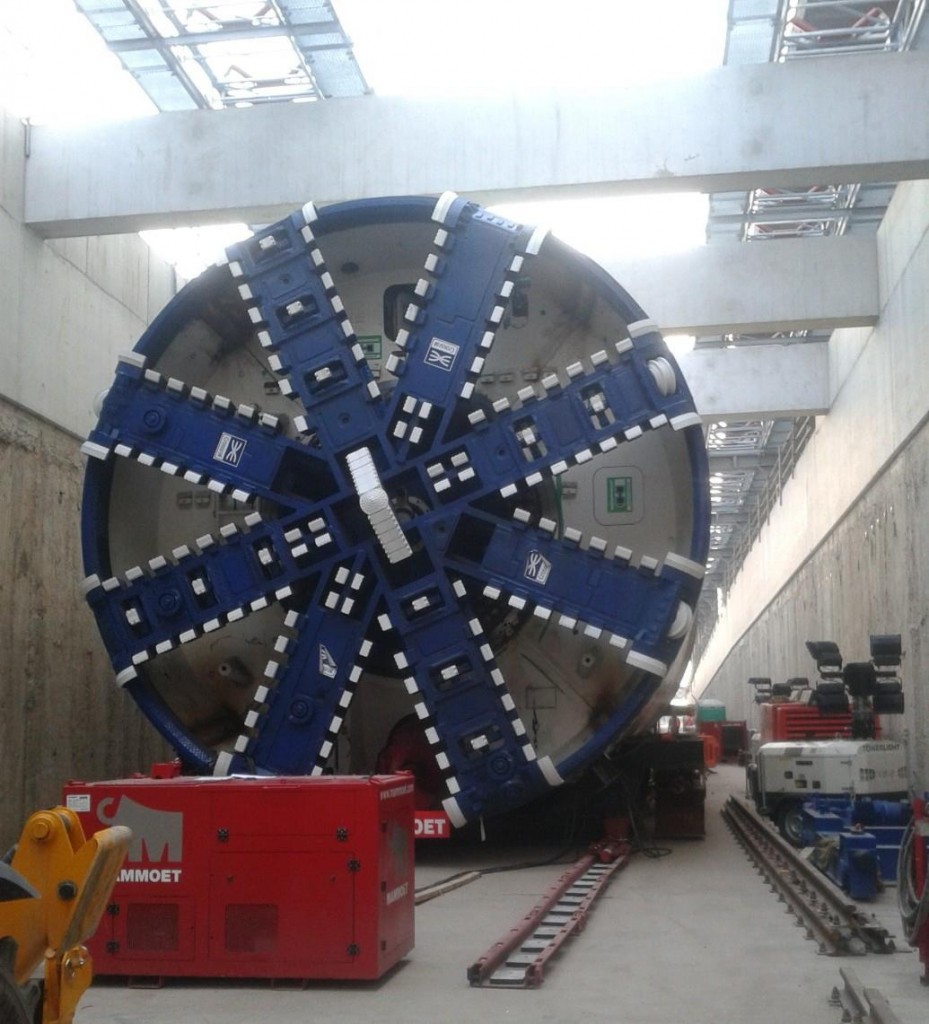
Figure 10 ‐ Crossrail Western Running Tunnels – TBM passing under first low level prop in launch chamber with only 20 mm clearance [Hickman, C, 2012]
The skidding equipment used included four skid shoes each with a 20 tonne push‐pull unit running in PTFE lined skid tracks. To ensure that the TBM would not slide out of control, engineers checked the frictional characteristics of the PTFE pads to ensure the TBM would stop when required. In addition to this the skid tracks were fixed in place and the skid shoes intermittently locked into these to ensure that the TBM was restrained at all times. Operating on a push‐pull cycle with a stroke of 600 mm the TBM advanced at a rate of 12 m/h towards launch position.
At the end of the launch chamber a 1.7 m high step had been included in the baseslab design. A steel bridge was installed so that the TBM could be skidded beyond the step. In order to get the TBM into launch position, the TBM was then jacked up using the climbing jacks strapped to the cradle structure. The steel bridge then had to be removed from below the TBM. The area below the TBM shield the bridge was designed so that all bracing could be removed from the outside to avoid the need for workers to access the area below the TBM. Chains were installed to the main bridge beams so that they could be dragged out from below the TBM using Tirfor winches.
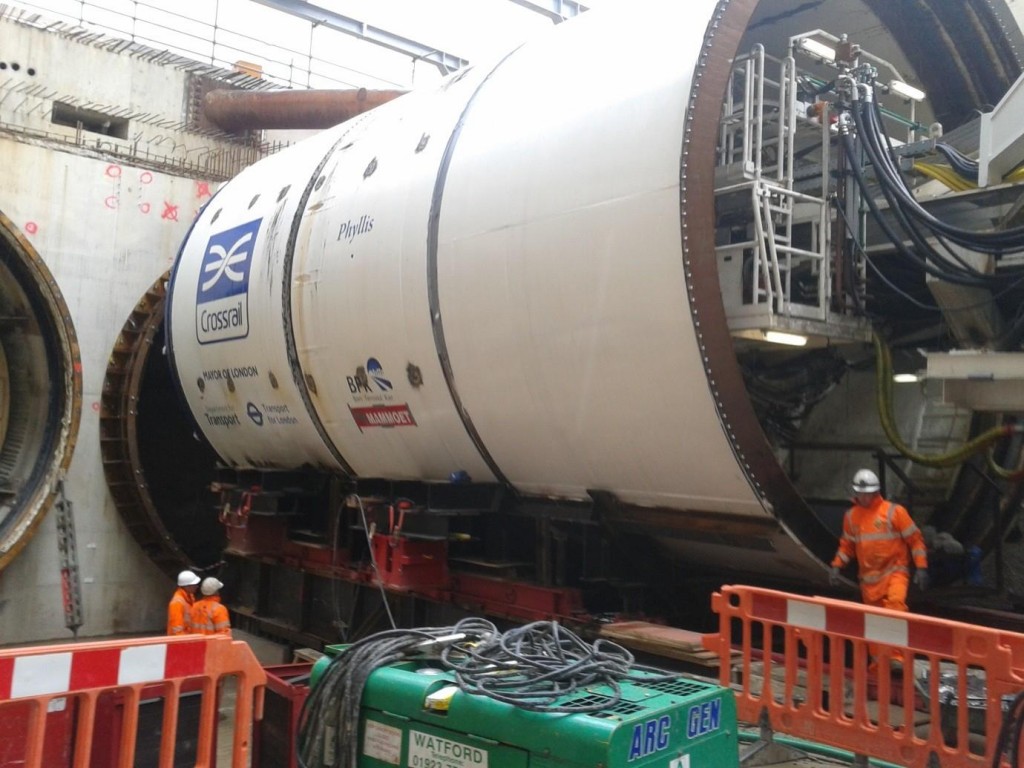
Figure 11 ‐ Crossrail Western Running Tunnels – TBM skidding onto steel bridge above launch position [Hickman, C, 2012]
2.2.4 Crossrail, TBM Transit through Bond Street Station
Advanced works were carried out at Bond Street Station to excavate the North West Shaft which will later form part of the Eastern Ticket Hall and construct a large proportion of the Eastbound Platform Tunnel. This meant that as the TBM arrived it would need to be transited trough the platform tunnel and then re‐launch from the shaft at the other end. The layout of the platform tunnels was restricted by openings in the shaft structure and a curve in the permanent tunnel alignment. This meant the TBM had to negotiate a series of curves during transit. The alignment of the TBM is shown in figure 12 below.
Tight curves in the transit alignment can cause issues when transiting TBMs for two reasons. Firstly, the TBM shield may be considered as a rigid cylinder during transit and therefore, it will not easily pass through a curve. As the length of the shield increases and the radius of the curve reduces this issue is exasperated. Secondly, the backup train will follow the shield through gradual curves but snagging may occur when curves are tightened. If two consecutive curves are included in the route the problem is worsened as the backups will try to follow the shortest path and will consequently ride up resulting in snagging issues and thus slowing the advance of the TBM.
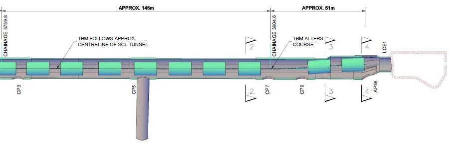
Figure 12 ‐ Crossrail Western Running Tunnels – Plan showing TBM transit alignment through Bond Street Station [Freeman, J, 2012]
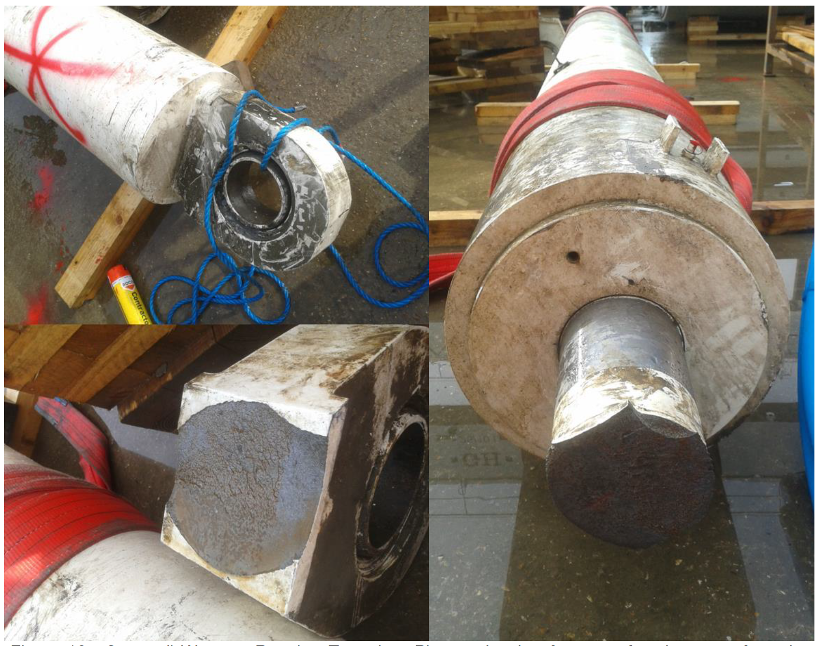
This problem was highlighted as miners attempted to negotiate a series of two consecutive 200 m radii at Paddington Station and one of the towing rams that connect the shield to the backup train failed. The cause of the failure could be attributed to a number of factors including casting defects, seizing of the bearing or excessive articulation of the joint but there is no doubt that the tunnel alignment was a contributing factor. The failed towing rams are shown in figure 13 below.

Figure 13 ‐ Crossrail Western Running Tunnels – Photos showing fracture of towing rams from the TBM bridge assembly [Hickman, C, 2012]
An additional consideration for transiting TBMs below ground is the reception arrangement. Guidance systems to control the TBM alignment has improved greatly over the years but some tolerance must be allowed for the location of the TBM arrival. There are several methods for accommodating this tolerance but in this case engineers chose to use a lean mix concrete invert with a transition section.
The lean mix concrete invert is cast prior to the arrival of the TBM and as the TBM arrives it cuts through the concrete invert to form a cradle at the correct height. Beyond the concrete invert, a steel or concrete cradle can be installed to suit the height and position of the TBM. In order to reduce the amount of work required after the TBM has arrived, the continuous cradle can be installed in advance and a transition arrangement used to adjust the level of the TBM. An example of the transition arrangement to be used at the Crossrail Bond Street Station is shown in figure 14 below.
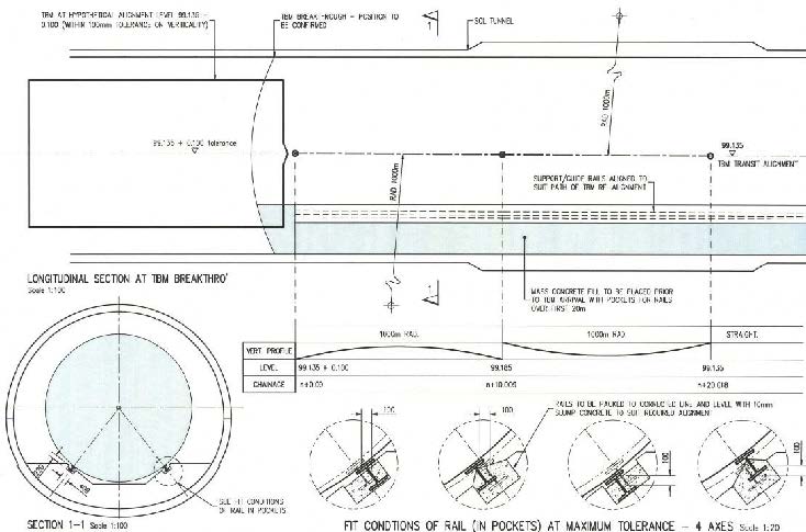
Figure 14 ‐ Crossrail Western Running Tunnels – TBM reception and transition arrangement [Freeman, J, 2012]
2.2.5 Ireland, Dublin Port Tunnel
A single TBM was used to construct the two running tunnels for the Dublin Port Tunnels. The TBM was launched and constructed the first running tunnel and then had to be turned through 180° so that it could be re‐launched for the return journey. In order to carry out this manoeuvre engineers chose to lift the 11.77 m diameter, 156 m long, 1600 tonne TBM using a combination of air bags and a crane. The TBM shield was detached from the backup train and lifted using airbags. Steel plates were laid across the transit area and were lubricated to reduce friction allowing the shield to be skidded into the new launch position. The backup gantries were then lifted one by one and joined to the back of the TBM.
The task of transporting a TBM whole is a complex procedure, the need for which should be identified early and considered carefully. If possible, the need for TBM transits and re‐launches should be highlighted at design stage and considered in the design of launch chambers and stations. For example, removing the need for curves at stations will smooth and accelerate the transit and re‐ launch of a TBM.
Continuous cradle systems reduce disruption to tunnelling activities and are therefore ideal for use in cases where transits are required through shafts and caverns along the tunnel route. However, due to the high cost of this option in terms of labour and materials a cost benefit analysis may be required as openings increase in length.
Currently there are two main options for transporting TBMs over longer distances; these include skidding and SPMT systems. The decision on which transit option to use will be influenced by a number of factors such as the required advance rate, height restrictions and foundation considerations. Cost may not be an issue as quotations show that the difference between each option is not significant which is probably due to the increased time and manpower required for skidding systems.
In the authors opinion, of the systems that have been developed for transporting the TBM backup train, the bogie and rail system is the most cost effective and efficient method. However, the design of the system should carefully consider curves in the transit route.
The examples in this report provide a useful reference to parties considering similar operations. The issues highlighted and solutions discussed identify some of the issues that can be tacked early to reduce risks and delays.
References and Bibliography
Dublin Port Tunnel, 2003. Dublin Port Tunnel Operations Information. [online] Available at:
http://www.dublinporttunnel.ie/about/building/ [Accessed 07 September 2012].Bern, K., Tunnel Boring Machine, Biel – Switzerland, 2011. VSL Job Reports. [online] Available at:
www.vsl.com/References/jobreport.php?getfile=JR2839 [Accessed 21 July 2012].Stehlik, E., 2011. Figure 1 – Prague Metro Line Extension. [photograph] (Ermin Stehlik’s own private collection).
Stehlik, E., 2011. Figure 2 – Prague Metro Line Extension. [photograph] (Ermin Stehlik’s own private collection).
Stehlik, E., 2011. Figure 3 – Prague Metro Line Extension. [photograph] (Ermin Stehlik’s own private collection).
ALE Heavylift Iberica, 2007. Figure 4 – Barcellona Line 9. [drawing] (BFK Technical Library).
ALE Heavylift Iberica, 2007. Figure 5 – Barcellona Line 9. [photograph] (BFK Technical Library).
Thomas, I., 2011. Figure 6 – Biel Bypass. [photograph] (Ivor Thomas’s own private collection). Thomas, I., 2011. Figure 7 – Biel Bypass. [photograph] (Ivor Thomas’s own private collection).
Hickman, C., 2012. Figure 8 – Crossrail Western Running Tunnels. [photograph] (Chris Hickman’s own private collection).
Hickman, C., 2012. Figure 9 – Crossrail Western Running Tunnels. [photograph] (Chris Hickman’s own private collection).
Hickman, C., 2012. Figure 10 – Crossrail Western Running Tunnels. [photograph] (Chris Hickman’s own private collection).
Hickman, C., 2012. Figure 11 – Crossrail Western Running Tunnels. [photograph] (Chris Hickman’s own private collection).
Freeman, J., 2012. Figure 12 – Crossrail Western Running Tunnels. [drawing] (Kier Construction ‐ Engineering design sketch).
Hickman, C., 2012. Figure 13 – Crossrail Western Running Tunnels. [photograph] (Chris Hickman’s own private collection).
Freeman, J., 2012. Figure 14 – Crossrail Western Running Tunnels. [drawing] (Kier Construction ‐ Engineering design sketch).
-
Authors

Chris Hickman MEng - BAM Ferrovial Kier
Graduate Civil Engineer, Bam Ferrovial Kier Joint Venture