In-tunnel depressurisation for SCL tunnels at Whitechapel and Liverpool Street stations
Document
type: Technical Paper
Author:
Roser Soler Pujol, Alessandra Colace, Dr Alfred Stärk Dipl Ing Dr Ing, W. Zeiszig, T.O.L Roberts, ICE Publishing
Publication
Date: 31/12/2016
-
Read the full document
Introduction
Crossrail contract C510 comprises the excavation of platform tunnels, concourse tunnels, cross-passages, escalators and ventilation ducts for the new Whitechapel and Liverpool Street Stations in London. The tunnels have been excavated using Sprayed Concrete Lining (SCL) techniques.
Works for both stations started with the sinking of an Access Shaft which allowed for the opening of two central cross-passages and the platform tunnels 30 m below surface, see Figures 1 and 2. The platform tunnels are approximately 240 m long, and these were mined in two stages: an initial pilot tunnel of approximately 6.3 m outside diameter was excavated first, followed by the 10.5 to 11.5 m diameter enlargement.
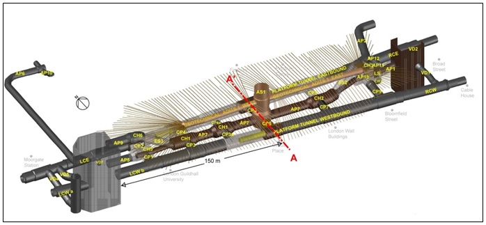
Figure 1 – CRL Liverpool Street Station 3D model showing the Access Shaft (AS1), Platform Tunnels, Concourse Tunnels, Cross Passages and Ventilation Ducts at a lower level; and Escalators and pedestrian links at the upper level. Also shown above the concourse tunnels are the Geotechnical Adits, which were used for the compensation grouting works. 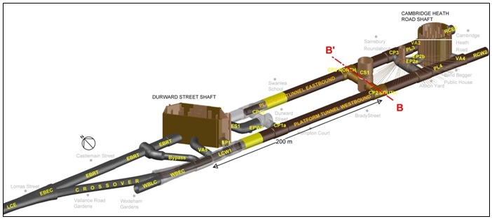
Figure 2 – CRL Whitechapel Station 3D model showing the Access Shaft (CS1), Platform Tunnels, Cross Passages, Ventilation Ducts, Escalator, Eastbound Running Tunnel, Caverns and Crossover. The new tunnels are in very close proximity to existing utilities, services and infrastructure. This included the Hammersmith and City Lines, Northern Line, Great North Eastern Railway, Post Office Tunnel and Goswell Sewer at Liverpool Street; and the London Overground, Hammersmith and City Lines and North Eastern Storm-Relief Sewer at Whitechapel. Ensuring the safety and stability of the face was critical to controlling settlements and meeting the necessary strict limitations on ground movements. In order to achieve this, before the SCL works commenced, a strategy was developed for identifying and controlling unacceptable excess pore pressures which might otherwise lead to invert or face instability.
This paper describes the depressurisation requirements and control strategy together with the performance data obtained during the construction of the tunnels.
Geological context
The ground profiles at Liverpool Street and Whitechapel stations are similar, comprising superficial Made Ground which overlies the River Terrace Deposits Unit (RTDU, the Upper Aquifer). This in turn, overlies the London Clay, Harwich Formation, Lambeth Group, Thanet Sands and Chalk, see Figure 3.
![Figure 3 - Liverpool Street Station initial Geological Model [1].](https://learninglegacy.crossrail.co.uk/wp-content/uploads/2016/12/7E-031-Figure-3.jpg)
Figure 3 – Liverpool Street Station initial Geological Model [1]. The Thanet Sand and Chalk make up the Lower Aquifer of the London basin, which has been over exploited in the past leading to a significant reduction in groundwater levels which is currently a few meters below the platform tunnel invert at both Whitechapel and Liverpool Street. The London Clay and Lambeth Group clays act as an aquitard separating the Upper and the Lower Aquifers. Confined lenses of sand were indicated to be intermittently present within the upper Lambeth Group forming an Intermediate Aquifer. Groundwater pressures in these sand horizons were recorded at 1 to 2 bar. It was unclear whether the significant variation in pore pressure measurements was due to genuine variation, the high sensitivity of the pore pressures (due to their limited recharge potential) or due to difficulties in measurement.
The Geotechnical Investigations undertaken prior to the works indicated that the tunnels for Liverpool Street Station would be excavated predominantly within London Clay, with the presence of Harwich Formation and the Lambeth Group at invert level, see Figure 3.
At Whitechapel Station the Geotechnical Investigations suggested that the tunnels would be mined in London Clay. The Harwich Formation and Lambeth Group were expected to be immediately below the invert of the tunnel, see Figure 4.
![Figure 4 - Whitechapel Station initial Geological Model [1].](https://learninglegacy.crossrail.co.uk/wp-content/uploads/2016/12/7E-031-Figure-4.jpg)
Figure 4 – Whitechapel Station initial Geological Model [1]. Depressurisation Plan
In order to identify and depressurise any potential water-bearing horizons within or below the tunnel excavation, a depressurisation plan was prepared prior to construction works. At initial design stage a surface well scheme had been proposed as a principal method of depressurisation in combination with in-tunnel vacuum wellpoints. However, surface wells had the following limitations:
- Limited access due to the congested urban environment.
- In many instances the proposed widely spaced surface wells might not intercept the channel sands which are of limited lateral extent.
- Surface wells are inefficient due to the short screen length in the target stratum compared to their overall depth.
- Given the low permeability of the channel sands and the expected low flow rates, surface wells would need to be pumped either by ejectors or submersible pumps with vacuum. Connection, control and monitoring of surface well array in the prevailing congested urban environment at ground level would have proved extremely challenging.
In view of the above an in-tunnel wellpoint depressurisation system was considered the most appropriate option for the majority of the tunnels at Whitechapel and Liverpool Street Stations. One exception to this was the Crossover, Eastbound Running Tunnel, Eastbound Cavern and Westbound Cavern at the west end of Whitechapel Station (Figure 2). The Geotechnical Investigation in this area identified extensive sand horizons and in addition surface access was available from Vallance Gardens above. This allowed the channel sands to be successfully targeted using surface vacuum wells [2]. Also the increased depth and configuration of the VD4 tunnel at Liverpool Street (see Figure 1) required the use of an in-tunnel ejector well system [3].
The general in-tunnel groundwater control scheme adopted comprised systematic probe drilling and installation of wellpoints, which would identify the presence of any water bearing granular sand horizons and, at the same time, provide for depressurisation.
Required clay cover versus pore pressure
An analysis of the face and base stability of a maximum 2 m invert advance concluded that the relationship between pore pressure in a sand horizon and the thickness of clay cover required was as shown in Figure 5. For simplicity the depressurisation plan was based on the assumption that 3 m of low permeability clay cover was required for a pilot tunnel and 4 m for an enlargement. This followed a careful review of the current pore pressure data which concluded that pore pressure above about 1.5 bar were not present.
![Figure 5 - Required clay cover versus pore pressure for pilot and enlargement tunnels [1].](https://learninglegacy.crossrail.co.uk/wp-content/uploads/2016/12/7E-031-Figure-5.jpg)
Figure 5 – Required clay cover versus pore pressure for pilot and enlargement tunnels [1]. In-tunnel ground investigation. Drilling patterns
The in-tunnel probe drilling and depressurisation strategy was developed to address each of three principal situations:
- Clay cover below invert of enlargement > 4 m (Standard drilling pattern) – No active depressurisation required.
- Clay cover below invert of enlargement < 4 m; and clay cover below invert of pilot tunnel > 3 m (drilling pattern Advanced 1) – Depressurisation for the enlargement tunnel required.
- Clay cover below invert of pilot tunnel < 3 m (drilling pattern Advanced 2) – Depressurisation for pilot and enlargement tunnels required.
The probe drilling was planned in two stages based on the minimum clay cover requirement for pilot and enlargement excavations. For the first stage, probe holes ahead would check the presence of sufficient clay cover for the pilot tunnel only (3 m).
The second stage, which would be undertaken after the completion of the pilot tunnels, involved near vertical investigation holes drilled from the pilot tunnel to confirm the thickness of clay cover below the enlargement (4 m). These probe holes would be completed as depressurisation wellpoints where non-cohesive soils were identified.
Extending the Phase 1 probe holes to prove the clay cover for the enlargements was considered but not pursued. This was because it was expected that probe drilling for the enlargement would encounter water bearing non-cohesive horizons at several locations which would require depressurisation. Since conditions in the pilot tunnel were likely to be artesian, inflows from these probes would have disrupted the pilot tunnel excavation. It was considered preferable to minimise this risk by probing for the enlargement in Phase 2, following completion of the pilot tunnels. This would also provide continuity of work for probe drilling as sections of pilot tunnel were completed.
The initial geological model for Whitechapel indicated sufficient cover below the invert of the enlargement in most areas (Figure 4); this meant that the Standard drilling pattern could be applied to confirm this situation.
The geological Model for Liverpool Street (Figure 3) indicated that more than half of the pilot tunnel length would be excavated predominantly in London Clay but with invert close to the top of the Harwich Formation and the Lambeth Group. Where the clay cover was indicated to be >3 m below invert of the pilot tunnel the Standard Drilling pattern was applied (Figure 6). In the areas where the geological model showed the top of Lambeth Group Formation rising into the face of the pilot tunnel, in some areas up to axis level, drilling patterns Advanced 1 and Advanced 2 were to be applied (Figure 6). Advanced 1 included provision of supplementary face probing to identify the base of the London Clay and Advanced 2 included an expectation for the need of supplementary probe holes, completed as wellpoints, to target high level sand horizons identified ahead of the face.
Details of the Standard, Advanced 1 and Advanced 2 drilling patterns used at Liverpool Street Station are given in Figure 7.![Figure 6 - Liverpool Street station, Enlargement Tunnel plan view. Advanced drill patterns were to be applied in the shaded areas (red), and standard pattern elsewhere [1].](https://learninglegacy.crossrail.co.uk/wp-content/uploads/2016/12/7E-031-Figure-6.jpg)
Figure 6 – Liverpool Street station, Enlargement Tunnel plan view. Advanced drill patterns were to be applied in the shaded areas (red), and standard pattern elsewhere [1]. For the pilot tunnel the Standard Pattern included, two probe holes (inclined downward) reaching 20 m ahead of the face in order to confirm the clay cover below. A single central upward probe hole was also included to prove clay cover to circa 2 m above crown level of the enlargement (approximately 4 m above the pilot tunnel crown). Note that no channel sand horizons were expected above the crown level, therefore clay cover above the enlargement could be covered with Phase 1 probing. In order to minimise disruption to tunnelling, the forward probe holes were planned at 16 m intervals, providing 4 m overlap. The distance between sets of probe holes would be reduced and the number of probe holes increased (Advanced 1 and 2 drilling patterns) if there was evidence of deteriorating ground conditions around or ahead of the face.
On completion of the pilot tunnels, an array of near vertical investigation probe holes were to be drilled downwards to prove conditions for the enlargement. The proposed drilling pattern comprised two probes each side of the pilot tunnel every 8 m, with one in the centre every 8 m in‐between. The probe holes were approximately 6.5 m depth to prove conditions for a minimum 4 m below the enlargement invert level.
![Figure 7 - Liverpool Street Station Standard, Advanced 1 and Advanced 2 drilling patterns [1].](https://learninglegacy.crossrail.co.uk/wp-content/uploads/2016/12/7E-031-Figure-7.jpg)
Figure 7 – Liverpool Street Station Standard, Advanced 1 and Advanced 2 drilling patterns [1]. If the probe holes encountered water bearing horizons then they were to be completed as wellpoints. Provision was made for extending installations by up to 2 m where the sand layer was encountered at 3 m or more below the enlargement interface, in order to maximise wellpoint screen length in the target stratum.
The outer wellpoints at the side of the pilot tunnel were planned to be used for depressurisation. This was achieved by connecting the wellpoints to a headermain and vacuum wellpoint pump. Since it was only necessary to control pore pressures in the immediate vicinity of the face the pumping system was continuously moved forward as the works advanced. The central wellpoints, located close to the face, were to be used as piezometers for monitoring purposes.
All probe holes were undertaken using auger drilling techniques. Wellpoint filters were installed to the required depth and additional lengths of riser were added as appropriate. The strategy included provision for using alternative methods of drilling if bores were unstable or if artesian conditions and ground loss were evident. These alternative methods included use of casing, drill through valves fixed to the lining, preventers and lost bit drilling. Inflows proved to be sufficiently low that these measures were generally not required.
Geological model updating
The drilling pattern applied was continuously reviewed following an assessment of the ground model, information on any sand horizons identified and feedback from the pumping and monitoring. The geological model was also constantly reviewed and updated based on the data collected from:
- Probe hole logs
- In-tunnel groundwater monitoring
- Surface groundwater monitoring
- Face logging
- Water pressures and flow
Drilling works were supervised and logged by a geologist or a trained engineer with arising assessed every meter (Figure 8). Probe hole and depressurisation well logs included the description of soils according to the BS-5930 and the presence of any groundwater strikes during the drilling. Special attention was given to the presence and extent of sand horizons.
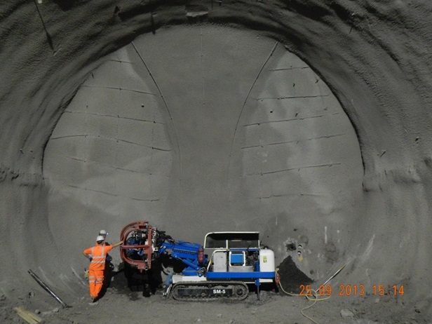
Figure 8 – probing ahead for the Westbound Cavern at Whitechapel Station. A depressurisation check sheet was completed for each round of investigation holes confirming pore water pressure, required clay cover, the actual clay cover, and a statement as to whether the tunnel excavation was to proceed with or without depressurisation.
If active depressurisation was required then further monitoring would take place during the dewatering process to confirm whether pore pressures had been reduced sufficiently to safely proceed with the excavation. As far as possible in-tunnel monitoring data was cross-checked with information from surface groundwater monitoring.
Face logs were also prepared for each pilot tunnel and enlargement advance. The face log included an annotated sketch of the exposed geology, a detailed geological description of the soil encountered, details of any discontinuities and groundwater seepage or inflow, a photograph of the face and observations on stability. An example of a face log is given in Figure 9.
A geological long section was also prepared and continuously updated. This was initially hand sketched so that the information was immediately available to the project team. The new geological information was also checked against the surface ground investigation boreholes already available.
The data collected was reviewed and crosschecked daily with in-tunnel and surface monitoring during the RES-SRG (Required Excavation Support – Shift Review Group) meeting, where an assessment of the safety and security of the SCL works would be undertaken.
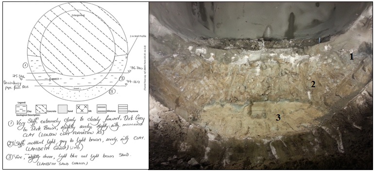
Figure 9 – Face log and photo recorded at Liverpool Street Station during excavation of AP1 Advance 19 deep invert. Date, signatures and location are not shown on the face log for the sake of clarity. Depressurisation results
Excluding the western end (Crossover, Eastbound Running Tunnel, Eastbound and Westbound Caverns and Bypass tunnel), the excavation for most of the tunnels for Whitechapel Station (Platform tunnels, Cross Passages and Ventilation Ducts) were completed with passive relieve only, as it had been expected. A few localised sections of the platform tunnels required active vacuum pumping prior to the enlargement works. In these areas, pore pressures were quickly controlled demonstrating the success of the depressurisation plan.
The need of active depressurisation was more extended at Liverpool Street which was a few meters lower in the geological sequence. The Lambeth Group was encountered within the pilot tunnel in most areas. The probe drilling identified large sand channels within and below the pilot and enlargement tunnels, which extended more than 10 m laterally in some cases.
The continuous review and updating of the ground model was essential for identifying target water bearing horizons and in understanding their response to pumping. The ground model allowed swift identification of areas where depressurisation was required or was insufficient. The value of the model was clear from a number of instances as follows:
- It was generally necessary to decommission wellpoints installed in the pilot tunnel ahead of enlargement. In some areas where channel sands were present within the enlargement it was necessary to install additional wellpoints from the enlargement, behind the face, to maintain the required pore pressure control as the enlargement advanced and pilot tunnel wellpoints were lost. These situations could be quickly identified from the ground model and appropriate strategies planned and implemented.
- It was sometimes possible to target a sand horizon from an adjacent parallel tunnel. This solution was used, for example, to depressurise a sand layer encountered within the pilot tunnel for Platform Tunnel Eastbound. Inclined wellpoints were installed from the parallel tunnel Access Passage 7. This had significant program benefits as the installation and operation of the depressurisation system did not interfere with the pilot excavation works. A similar solution was adopted to support depressurisation of the deep invert at Access Passage 1, see Figures 9 and 10.
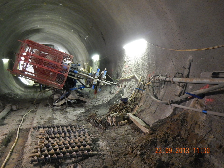
Figure 10 – Liverpool street station, installation of additional inclined well points from Reception Chamber East (RCE) towards Access Passage 1 (AP1) to support the depressurisation of AP1 deep invert. - The ground model allowed identification of zones where the wellpoints were targeting different sand horizons sometimes at different levels. Under these circumstances the efficiency of the depressurisation system could be improved by using additional wellpoint pumps to target each sand horizon independently.
- Assimilation of the geological information obtained during the excavation of the platform tunnels (probe hole, wells and face logs) allowed a far better understanding of the ground conditions that would be encountered during the excavation of the remaining Cross Passages and Ventilation Ducts. This allowed the scale of the probe drilling for these latter works to be significantly reduced to primarily target non-cohesive soils that had been previously identified.
Flow rates from the channel sands encountered were relatively low, typically in the range of 2 to 10 l/min.
An example: Depressurisation of Cross Passage 5 at Liverpool Street
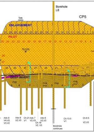
Channel Sands were encountered during probe drilling of CP5, see Figure 11. This had been anticipated from the initial geological model, see Figure 3. The probing drilling confirmed the presence of groundwater associated with the channel sands. Following a review and assessment of the clay cover thickness and pore pressures present, it was concluded that the pilot tunnel could be safely completed without the need for pumping. However active depressurisation was required to safely mine the subsequent enlargements.
![Figure 11 - CP5 Geological long section based on initial CRL surface bore holes, probe drilling and wellpoint installation logs and face logs [4].](https://learninglegacy.crossrail.co.uk/wp-content/uploads/2016/12/7E-031-Figure-11.jpg)
Figure 11 – CP5 Geological long section based on initial CRL surface bore holes, probe drilling and wellpoint installation logs and face logs [4]. The depressurisation scheme for CP5 was carried out in stages. The first stage was undertaken after completion of the pilot tunnel, prior to excavation for enlargement. The depressurisation wellpoints were installed within the pilot tunnel and connected to a vacuum system, see Figures 11 and 12. Initial readings indicated sub-artesian groundwater levels at 76.00 to 77.5 m ATD, which was above the target level of 75.3 m ATD required for the initial enlargement excavation. When pumping commenced, groundwater levels dropped to between 74.19 m ATD (chainage 13.51 m) to 75.88 m ATD (chainage 21 m), allowing excavation of the enlargement to proceed, see Figure 13.
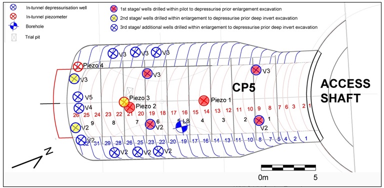
Figure 12 – CP5 depressurisation scheme plan view including the pilot tunnel wellpoints (1st stage), and the enlargement wellpoints (2nd stage). The second stage involved installation of supplementary wellpoints from the initial enlargement prior to the excavation of the CP5 deep invert. Pumping on these supplementary wellpoints reduced pore pressures to below 73 m ATD allowing the invert excavation works to proceed.
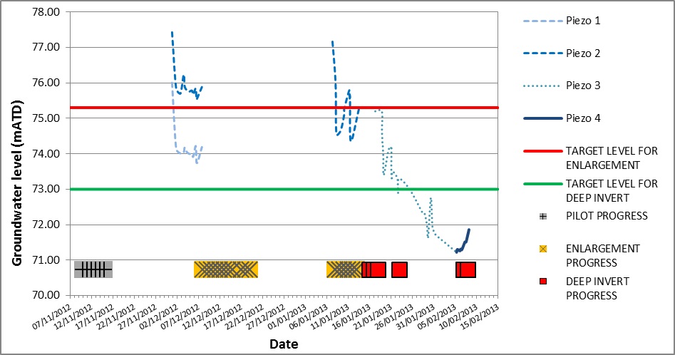
Figure 13 – CP5 in-tunnel groundwater monitoring from un-pumped wellpoints during excavation of the enlargement and deep invert. Excavation progress and depressurisation target levels are shown for each stage (enlargement and deep invert). Figure 13 shows manual in-tunnel groundwater monitoring data recorded prior to the excavation of the invert. Groundwater levels were successfully reduced to below target level (73.0 m ATD). The subsequent excavation was generally dry and stable.
Conclusion
A systematic approach to in-tunnel depressurisation was adopted for the construction of the majority of Whitechapel Station and all of Liverpool Street Station. The solution implemented involved the installation of relatively shorter and efficient in-tunnel wellpoints that could target the intermittent channel sands more effectively compared to the surface well scheme approach originally proposed.
A two stage approach was adopted for probe drilling, with Phase 1 for the pilot tunnel only, followed by Phase 2 for the enlargement. This minimised disruption to the progress of the tunnelling works, if the sequence of excavation was not modified, and provided continuity of drilling for Phase 2. A series of standard drilling patterns was developed based on the expected geological conditions indicated by the ground model.
The collection and assimilation of geological data, which was used to update the ground model, played a major role in improving the efficiency and success of the dewatering. The up to date ground model, combined with the pore pressure monitoring data, provided a good understanding of the connectivity and the resulting extent of influence of the in-tunnel wellpoints. This allowed rapid identification of areas requiring depressurisation and development of modified or alternative strategies where the installed scheme needed to be improved.
References
[1] Stärk, A., Zeiszig, W. and Brown, D.A. (2012) Whitechapel and Liverpool Street Station Tunnels. Depressurisation Plan Rev. 5.0. Crossrail – BBMV-JV C510, BBMV Document Number C510-BBM-C2-GPD-CR092-50001.
[2] Colace, A. and Stärk, A. (2014). Depressurisation and Surface settlement at Vallance Road Garden, Whitechapel. Crossrail Project: Infrastructure Design and Construction (Volume 2) – Black, Dodge and Lawrence (eds.) – ICE Publishing.
[3] Roberts, T.O.L, Smith, R., Stärk, A., Zeiszig, W. (2014). Sub-surface dewatering for an inclined SCL tunnel. Crossrail Project: Infrastructure Design and Construction (Volume 2) – Black, Dodge and Lawrence (eds.) – ICE Publishing.
[4] Colace, A., Soler, R., Stärk, A. and Brown, D.A. (2015). Geological Interpretative report for CP5 and CP6 at Liverpool Street Station. Rev 1.0. Crossrail – BBMV-JV C510, BBMV Document Number C510-BBM-C-RGN-C101-50042
-
Authors


Dr Alfred Stärk Dipl Ing Dr Ing - BeMo Tunnelling
Dr Alfred Stärk is Chief Geotechnical Engineer and Engineering Manager at BBMV for Crossrail Contract 510 ‘Whitechapel and Liverpool Street Station Tunnels’ since March of 2011. He started his career at the University of Hanover, Germany, where he worked as assistant professor and consultant for 10 years. In 2002 he joined BeMo Tunnelling, Innsbruck, Austria. He now has 25 years of experience in large-scale tunnelling, mainly with sprayed concrete lining in soft ground.
W. Zeiszig
BeMo Tunnelling
T.O.L Roberts
WJ Groundwater Ltd
