Use of TBM pilot tunnels for large diameter SCL caverns: the benefits, challenges and successes of Crossrail contract C300/C410
Document
type: Technical Paper
Author:
Adrian St.John, BEng (Hons) Eur Ing FICE CEng, Vicky Potts MA MSc PhD, Olivia Perkins MEng(Hons), Zsolt Balogh MSc, ICE Publishing
Publication
Date: 07/09/2015
-
Read the full document
Notation
BFK BAM Ferrovial Kier JV, the Main Contractor
BOS Bond Street station
CRL Crossrail Ltd, the Client
C121 Mott MacDonald, the Client’s SCL designer
DAL Donaldson Associates Ltd, the Contractor’s SCL designer
EPB Earth Pressure Balance (TBM)
HSE The Health and Safety Executive
ISL Initial Sealing Layer (usually 75mm shotcrete applied to the ground)
OCI Optimised Contractor Involvement
PTE Platform Tunnel Eastbound (enlargement)
PTW Platform Tunnel Westbound (enlargement)
SCL Sprayed Concrete Lining
SFR Steel fibre reinforced
TAM Tube à Manchette for compensation grouting
TBM Tunnel Boring Machine
TCR Tottenham Court Road station
TM Temporary Measure or “toolbox item” such as spiles or pocket excavation which could be deployed in the field to assist excavation stability1.0 Introduction
Crossrail is Europe’s largest construction project, and will transform rail transport in London, increasing capacity by 10%, supporting regeneration and cutting journey times across the city. The Crossrail route will run over 100km from Maidenhead and Heathrow in the west, through new tunnels under central London to Shenfield and Abbey Wood in the east. There will be 38 Crossrail stations including 9 new stations at Paddington, Bond Street, Tottenham Court Road, Farringdon, Liverpool Street, Whitechapel, Canary Wharf, Custom House and Woolwich.
A joint venture of BAM Ferrovial Kier (BFK) was awarded the Crossrail contract C300/C410 “Western Running Tunnels and Station Caverns” in January 2011. This comprised the construction of two 6.2km tunnel drives between Royal Oak and Farringdon and the construction of sprayed concrete lining (SCL) tunnels for Bond Street and Tottenham Court Road Station tunnels.
Donaldson Associates (DAL) was appointed as BFK’s SCL designers for these works. Both BFK and DAL had a clear responsibility for excavation stability. DAL’s scope of work comprised a Due Diligence Review (DDR) of the Client’s primary lining design, which formed part of the permanent works, and the design of “Toolbox items” and any other necessary measures required wherever an unacceptable risk of instability during excavation was identified. To supplement this, a 24/7 team of Senior SCL Engineers and SCL Shift Superintendents from Donaldson Associates was embedded into the BFK Engineering team.
This paper describes how the project used TBM tunnels as the pilot tunnels for the construction of large diameter SCL platform tunnels at Bond Street station and Tottenham Court Road stations. The paper examines the rationale behind this approach, and the numerous and various benefits which the project enjoyed as a result. These benefits included health and safety and sustainability, as well as yielding significant reductions in settlement, cost, programme and risk. The paper also discusses the various technical challenges which were overcome in order to successfully deliver this innovative solution.
2.0 Concept of “TBM first” strategy
The Client’s reference design for the separate contracts C300 and C410 assumed that the SCL station caverns would be constructed ahead of TBM passage. The BFK tender team recognised the potential of challenging and reversing this assumption and combining contracts C300 and C410 together into a single project. This initiative placed a considerable additional burden on the team to deliver both the compliant and alternative tender submissions within challenging tender timescales, but proved to be a key BFK “bid-winning” idea.
This proposal permitted the TBMs to complete their journey to Farringdon as quickly as possible, and provided the SCL team with a large diameter precast concrete pilot tunnel to be enlarged to full platform size using sprayed concrete linings.
The benefits of the BFK alternative approach included:
- Safer construction technique – a substantial increase in closed-face EPB tunnelling rather than open face SCL methods.
- Reduction in settlement by approximately 30%, through the use of a large diameter pilot tunnel constructed by an EPB TBM rather than open face SCL. This was of particular benefit given the sensitivity of the buildings in this area[1].
- Elimination of 50,000 lorry movements from central London roads, through the use of underground logistics systems linking to Westbourne Park, with consequential benefits of reduction in noise, dust, pollution and traffic.
- Forecast cost savings in excess of £80m.
- Reduction of approximately 7 months on the programme.
- Continuity of working for both the TBM and SCL teams, thus de-risking the programme interface and avoiding a demobilisation/remobilisation of the SCL and compensation grouting crews. This continuity permitted BFK to source, up-skill and retain key specialist SCL labour and resource during the contract period, in a specialist market with scarce resources and a very high demand.
- Simplification of TBM transits through the station areas through avoidance of temporary works, saving circa 500 tonnes of temporary steelwork.
- Omission of TBM reception and re-launch chambers constructed using SCL.
- Increased certainty of TBM arrival dates at Farringdon, reducing interface risk with other contracts.
- Significant reduction in project/programme risk owing to the criticality of having SCL caverns complete ahead of TBM transit in the reference design. These caverns were the largest ever SCL caverns to be constructed in London and were the first SCL works to be constructed on Crossrail. Furthermore, construction of these caverns could not commence until access shafts had been completed by other Crossrail contractors, major utility diversions had been completed, compensation grouting shafts had been installed, kilometres of Tube à Manchette (TaM) drilled and pre-treated and thousands of settlement monitoring points installed and baselined. Whilst theoretically possible, any of these activities could quickly have impacted upon critical TBM passage [see Figure 1].
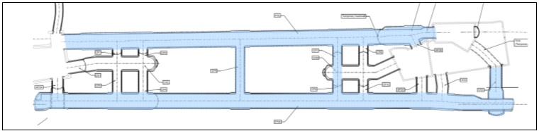
Figure 1 -Under the original scheme, more than 500 linear metres of platform cavern (highlighted in blue) would have needed to have been complete prior to TBM arrival, including all the associated temporary works to receive, transit and re-launch the TBMs
- Substantial reduction in Compensation Grouting and monitoring resources.
- Less onerous SCL platform enlargement due to significant reduction in face area using a large TBM pilot tunnel, including the combination of bench and invert into one SCL excavation step [see Figures 2 & 3].
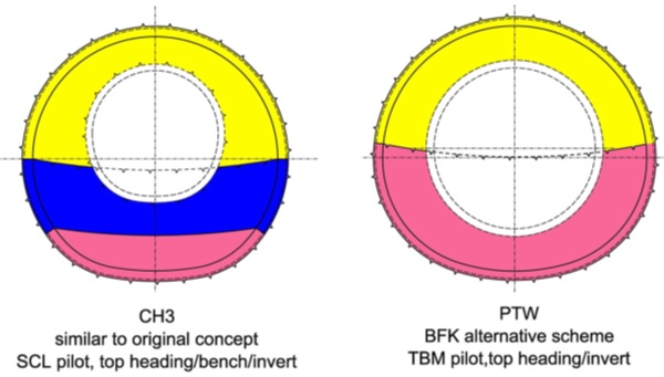
Figure 2 -Comparison between the original client scheme and the BFK alternative with “TBM first”
- 20% reduction in concrete wastage, driven by an increase in TBM tunnelling and corresponding decrease in SCL tunnelling.
- More cost-effective and sustainable spoil disposal via underground conveyor to Westbourne Park and onwards to Wallasea Island via train and ship.
- Increased Client and Stakeholder confidence (particularly London Underground) in the project arising from all of the above benefits.
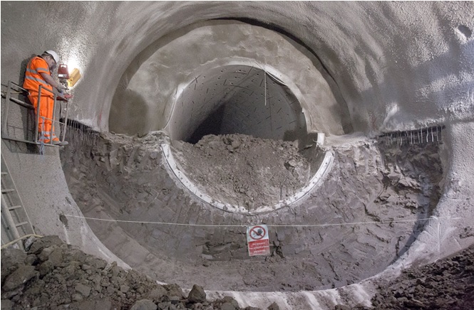
Figure 3 – Precast concrete pilot tunnel being enlarged to full platform size (1om high x 11m wide)
Adoption of the BFK alternative scheme was a considerable departure from the Client’s original plans and the baseline design. The contract commenced with an “Optimised Contractor Involvement” period (OCI), and one of the key challenges during this period was for all parties to fully understand the BFK alternative bid and to implement the required changes, particularly to the Client’s SCL design. This required very close collaboration between the Project Manager’s team, the Client’s designers, the Contractor’s team and designers, and set the scene for the successful integration of the project team to deliver the contract.
3.0 Design development
Because the design philosophy for SCL tunnels on C300/C410 envisaged the primary lining being used as part of the permanent works, a bespoke division of responsibilities between contractor and designer was developed for this project. This is described in detail by St.John et al[8], however the underlying principle was that the Employer’s SCL designer (Mott MacDonald) retained responsibility for the design of the primary lining at all construction stages, whilst the contractor (BFK) and their designer (DAL) were responsible for the stability of the excavation. Whilst unusual, this arrangement was consistent with the recommendations of the HSE report following the Heathrow Collapse[7], other HSE[6] and ICE guidance[5], and Crossrail Information Paper D23[2].
This division of responsibilities inevitably required a high level of collaboration between all parties, allowing the contractor’s preferred methods of working to be incorporated into the design. This was one of the key objectives of the OCI period, for all parties to understand the implications of the BFK alternative bid, and for the required design changes to be implemented in order to successfully deliver the “TBM first” concept. An example of this is the wraparounds at Bond Street and Tottenham Court Road stations; these were developed as a safe means of accessing the tunnels to start the platform tunnel SCL works where there was no direct access from one of the ticket hall boxes. The basic concept is illustrated in Figure 4, and involved the steps outlined below:
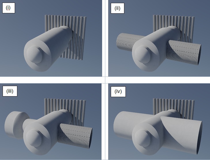
Figure 4 -Wraparound design concept
(i) construction of a large wraparound tunnel perpendicular to the platform tunnel alignment, prior to the arrival of the TBM;
(ii) backfilling the wraparound with foam concrete so that the TBM could drive through;
(iii) removal of the foam concrete, and commencement of SCL tunnelling along the platform tunnel alignment. To limit the size of the wraparound, the SCL tunnelling did not commence at the full platform tunnel profile. Instead a temporary transition was constructed with a smaller diameter excavation from the wraparound, flaring up to the full platform tunnel profile at a suitable distance from the wraparound.
(iv) SCL tunnelling would continue until an alternative access was created, and it was possible to refill the wraparound with foam concrete, and back excavate through the flare, transition and wraparound to construct the primary lining of the final platform tunnel.
Should there be time after completion of the wraparound, SCL tunnelling could commence using an SCL pilot for the transition and platform tunnels before the TBM arrival. This gave programme flexibility, which was a huge benefit given the difficulties associated with co-ordinating the interface between the TBM and SCL tunnelling works. For example at Bond St station, only the tunnels shown in blue in Figure 5 needed to be complete prior to the arrival of the TBM. However if time permitted and/or the TBM was delayed for any reason, it was possible to commence the works in red using SCL ahead of the TBM arrival.
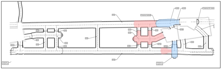
Figure 5 – Extent of works to be completed ahead of TBM arrival at Bond St (blue) with additional flexibility (red) depending on actual TBM advance rate
The wraparound concept incorporated the use of the running tunnels as platform tunnel pilots and as such the design was only initiated during the OCI period. A pragmatic approach to the design was needed – for example limiting the size of the wraparound and transition to avoid difficulties associated with the additional ground movements inherent with a larger structure and to allow the use of typical parent-child tunnel detailing – to enable rapid completion of the design so that these structures could be included in the advance works.
4.0 Detailed constructability issues and challenges
A number of key issues arose as part of the practical and successful application of the “TBM first” concept.
1m long temporary rings
The TBM and SCL advance lengths needed to be harmonised; the usual length for segmental SFR rings in running tunnels was 1.6m, compared with a standard excavation length for SCL tunnels in London Clay of only 1.0m.
A series of temporary 1.0m long rings were cast which were installed through the stations in order to match the SCL advances and allow the progressive removal of segmental rings in line with the SCL excavation advances. Matching the segment length to the SCL advance length ensured sufficient working space was created for excavation and spraying plant to achieve a high quality lining.
Harmonising the TBM pilot construction and SCL works also meant that the “as built” position of the segmental rings defined the chainages of excavation advances for the SCL works. In general this worked well, although it was more complicated towards the ends of the platforms where the leading edge of the segments was not parallel to the theoretical SCL advances, and some permanent rings required removal as part of the platform tunnel enlargement.
One particular issue arose at the interface between the permanent (1.6m) and temporary (1.0m) rings, since this “as built” position also defined the position of the permanent headwalls at the ends of the platform tunnels. This required flexibility in the design to ensure that the final spaceproofing and geometry was acceptable.
Each ring was 6.2m internal diameter, 300mm thick and consisted of 7 segments plus a key. The TBM pilot was typically positioned along the centreline of the future platform tunnel enlargement [see Figure 6]; this was not always possible and led to further complexities which are described in the next section. The segments contained no bar reinforcement which allowed relatively quick and easy demolition and crushing.
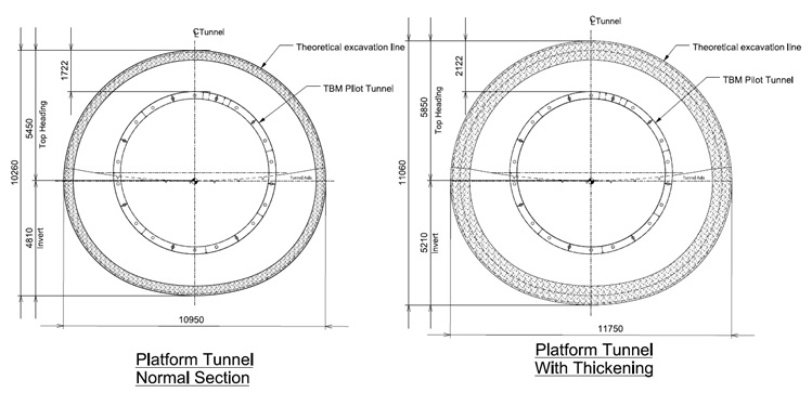
Figure 6 – Typical SCL Platform Tunnel cross sections with TBM pilot tunnel
Temporary TBM alignment
The permanent works alignment within the 250m long platform caverns required the track alignment to be located at one side of the tunnel, with platform edge screens and a wide platform on the other. The interface between running tunnel and platform tunnel therefore met with an eccentric connection [see Figure 7]. This added to the complexity of the detailed SCL advance sequencing, particularly in respect of the large top heading face area away from the TBM pilot. However, the favourable ground conditions across Bond Street and Tottenham Court Road stations meant no Temporary Measures, face subdivision or pocket excavations were required.
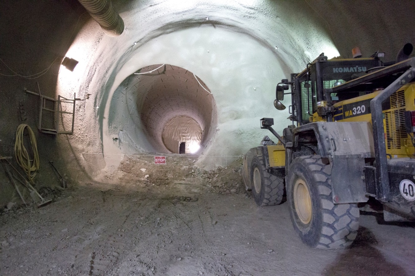
Figure 7 – Permanent headwall at the end of the platform tunnel, showing the eccentric relationship between the permanent running tunnel and the platform tunnel
The preferred TBM alignment from an SCL perspective was therefore clearly for the TBM to remain on the centreline of PTW and PTE for as much of the platform as possible, to give sufficient working space between the extrados of the PCC lining and the SCL excavation profile. The temporary TBM alignment therefore required careful consideration and negotiation with the BFK bored tunnels team; whilst the TBM could theoretically drive around a single 200m-300m radius, it was not designed to negotiate the back-to-back S curve required to transition the TBM from centreline of PTW/PTW to the centreline of the permanent running tunnel. To prevent damage to the TBM, a compromise was agreed which entailed a short section of straight tunnel at the point of contraflexure within the S bend. These chicanes in the temporary TBM alignment were required at each end of all the platform tunnels, and required particular care from both a design and construction point of view [see Figure 8].
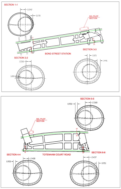
Figure 8 – Bond Street and Tottenham Court Road Stations showing the temporary TBM alignment (green) and the effect of the chicane arrangement in respect of the position of the TBM in the SCL face
The most extreme situation was at Bond street station, at the western end of PTE, where the TBM pilot tunnel extrados was positioned approximately 180mm beyond the permanent profile of the SCL platform tunnel [see Figure 8 Section 1-1]. This was dealt with by lowering the joint between top heading and invert [see Figure 9].
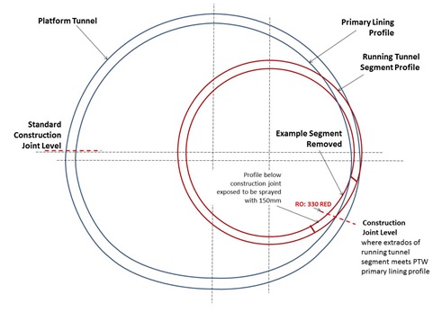
Figure 9 – Longitudinal construction joint detail to cope with eccentric pilot tunnel
At the extreme ends of the platform tunnels, the permanent SCL headwalls wrapped around the precast concrete running tunnel segments. Spraying the headwall required the excavation of the clay around approximately half of the length of the last permanent ring, and the site team were concerned about the temporary stability of that ring, particularly in the event of an accidental load (e.g. from plant impact). In order to assure the temporary stability of that ring, and to ensure that the gaskets remained intact and effective, steel needle beams were designed and installed to lock the last two permanent rings together [see Figure 10]. This was a simple and elegant solution which did not restrict traffic flow, and could be easily removed once the permanent SCL headwall had been completed.
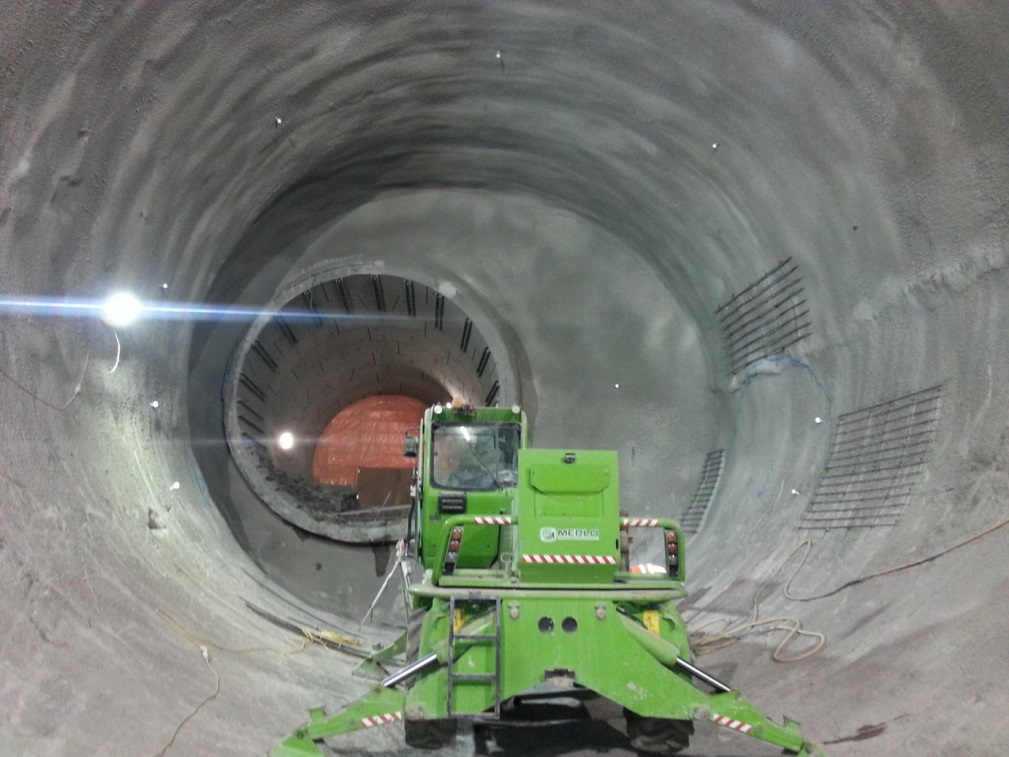
Figure 10 – Longitudinal “needle beam” support of permanent PCC rings at platform tunnel headwalls, to provide temporary restraint and to ensure that the EPDM gaskets remained fully effective
Detailed excavation sequencing
The total face area of platform tunnel was 96.2m2, of which the face of TBM pilot tunnel was 36.3m2. During enlargement of the TBM pilot tunnel to SCL platform tunnel profile, the remaining 59.9m2 of excavation face area was split into top heading and invert excavation steps. The Employer’s SCL design assumed a stagger of between 1m and 3m (2 x 1m top headings, followed by 1 x 2m invert – see Figure 11). Whilst this provided rapid ring closure and quickly arrested in-tunnel convergence and surface settlement, it created an extremely steep face of clay. In reality, this theoretical 1m (minimum) stagger between top heading and invert was shortened due to the doming of the face. The face stability (and lack of bearing beneath the top heading) was therefore of some concern to the project team; stability was assessed using Davis et al[4] and careful geotechnical logging was carried out on every advance to give early warning of any face instability.
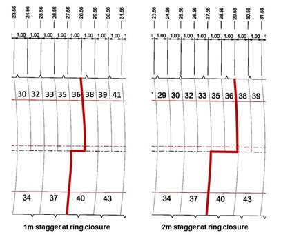
Figure 11 – Example alternative advance sequence stagger of 1m and 2m at ring closure
In contrast, a stagger of 2m and 4m (again with 2 x 1m top headings, followed by 1 x 2m invert) provided better face stability and a larger (and hence safer) working platform for the miners to install the joint Kwikastrip, but this greater stagger slowed down ring closure, with potential adverse effects on both convergence and surface settlement.
The design retained a degree of flexibility so that we could change from 3/1 to 4/2 according to the geotechnical conditions encountered, the convergence measurements and the surface monitoring results.
Compensation grouting exclusion zones
Throughout all excavation works the surface movements were monitored 24/7 using a range of automatic and manual instrumentation. The readings from all instrumentation in a defined zone of influence around the advancing tunnel face were reviewed daily at the Shift Review Group (SRG) meeting.
The slopes and distortions induced by the tunnelling works were controlled using concurrent compensation grouting and grout jacking. Compensation grouting was undertaken both ahead of and behind the advancing SCL face, but always beyond an exclusion zone designed to protect the face and incomplete rings of SCL from additional loading [see Figure 12]. The compensation grouting design ahead of the tunnel face was based on predicted ground movements, and adjusted as works progressed depending on the observed effectiveness of the treatment. Rear injections were based on observed ground movements. Where necessary further grout jacking passes were implemented later.
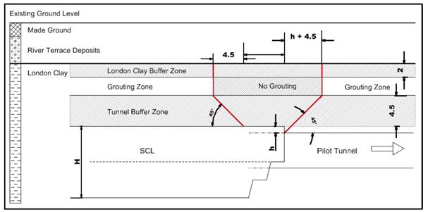
Figure 12 – Compensation grouting exclusion zone
In areas where larger ground movements were recorded, the length of the exclusion zone could be shortened by reducing the distance to ring closure behind the face, thereby providing better control of ground movements. However this needed to be balanced against the potential increase in risk to face stability and the overstress of an immature shotcrete tunnel lining. The situation was reviewed on a case by case basis taking into account a number of factors such as the early age strength gain of the shotcrete with time, the clearance between the TaMs and the tunnel crown, and the ground conditions and soil strengths logged during the most recent excavation rounds. If, after review, it was considered appropriate the exclusion zone could then be amended to suit.
5.0 Construction issues
Plant selection, method and logistics
Prior to commencement of the platform tunnels at Bond Street and Tottenham Court Road, there was a lengthy debate within the project team regarding the precise method and timing of the removal of the TBM segments, particularly in respect of ensuring a Safe System of Work (SSoW), noise, dust, vibration, logistics and disposal.
In reality, the removal of the segments was a simple process. There was a process of trialling different methods by the mining teams as the platform tunnel progressed. However a safe, optimum process was very quickly established.
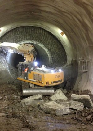
Firstly, a tunnel excavator, either a Liebherr 944 or 924, would remove the clay immediately around the ring, From initially trialling the breaker attachment and pulveriser attachment [see Figure 13] it was found that the bucket could be used, allowing excavation to continue uninterrupted without the need for an attachment change. Ensuring an exclusion zone[3] was in place at all times at the face, the bucket could either be used to knock out the ‘key’ segment from the extrados of the TBM tunnel or alternately be used on the intrados of the TBM tunnel, pushing the crown segments out and lowering them down with the back of the bucket [see Figure 14]. Both methods encouraged the crown section to be demolished in a controlled manner to approximately the axis level, from where the rings were supported by the unexcavated invert section. It was not required to remove the circumferential or radial bolts prior to this process, they could be removed as part of the disposal process as well as the rubber gaskets. This simple method of removal meant the extraction process could be undertaken quickly and efficiently, enabling prompt face sealing.
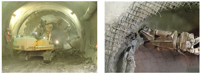
Figure 13 – Trialling the breaker and pulveriser attachments
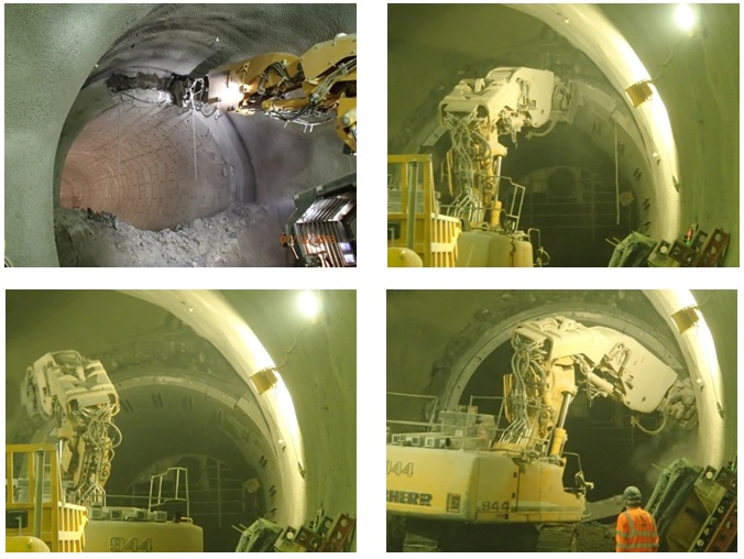
Figure 14 – Clockwise from top left; Excavating around the TBM segments; pushing out key segment; crown segments removed; pulling forward remaining segments into the exclusion zone.
Spoil handling and logistics
At time of commencing the platform tunnels, both BOS and TCR were primarily using a cross conveyor system disposing onto the still active, eastbound running tunnel TBM conveyor to dispose of all excavated spoil. This meant all spoil was restricted to a maximum size of 150mm.
A concrete crusher was employed on both sites to break up the concrete segments, however this required some pre-breaking down of the segments by an excavator with an attached hydraulic breaker. This required an additional excavator on site, working space in the tunnels, and introduced dust and noise concerns within the tunnel. This was a slow process and also required sorting of the crushed segments to remove bolts and the rubber gaskets from the segments.
To accelerate removal of the segments, an alternative solution was found which entailed lifting intact segments up to the surface in skips and transferring to muck away wagons. A clay base was put in the skips and wagons to minimise noise during transfer.
Advance rates
The platform tunnels advance rates were initially restricted to 3m/24hrs by the designer. Due to the swift removal of the TBM rings, which allowed for a good routine in the mining activity, this advance rate was consistently achieved.
Early age shotcrete strengths generally exceeded the specified requirements which, following a review by the designers, permitted us to advance more rapidly. This was closely monitored at the SRG and definition of the advance rate depending on the latest early age strength data was agreed and defined on the RESS.
Given this, the advance rate for the platform tunnels generally was between 3-4m/24hours, although there were periods where the project team achieved 5m/24 hours.
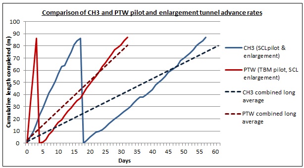
Figure 15 – Comparison of CH3 and PTW pilot and enlargement tunnel advance rates
To consider the benefit of a TBM pilot over an SCL pilot in terms of advance rates, two comparably sized tunnels at Tottenham Court road have been considered over an equivalent length as seen in Figure 15. CH3 tunnel was driven using an SCL pilot and enlarged using a top heading, bench and invert sequence. This tunnel had a combined long average of 1.5m/day. By contrast, the PTW tunnel, constructed using a TBM pilot and enlarged with a top heading and invert sequence had a combined long average of 2.8m/day; nearly twice as fast as CH3.
6.0 Behaviour and performance review
Convergence behaviour
In-tunnel convergence monitoring was based on arrays of monitoring points around the lining at roughly 10m spacing along the length of the tunnel.
For the purpose of comparing the performance of TBM and SCL pilots, CH3 and PTW at Bond Street had similar final profiles [see Figure 2], were at similar levels, and the centrelines were only 19.9m apart; the ground conditions for the two tunnels were therefore very similar. The convergence behaviour of the two tunnelling approaches can be seen in Figure 16. This shows exaggerated deflection profiles for the intrados of these two tunnels shortly before the regulating layer, waterproofing and secondary lining were applied, and after the construction of the nearby cross passage CP10 which linked the two tunnels.
The deflections for CH3 were significantly higher than for PTW; at the crown the settlement of CH3 was 43mm, compared with 35mm recorded for the nearest monitoring array in PTW, which was the larger of the two tunnels. This reduction in crown movement is attributed to the use of a TBM to construct the pilot tunnel in PTW, which provided better short term support to the ground during pilot construction than an SCL pilot, a smaller remaining face area for the enlargement excavation, and allowed a top heading/invert sequence for the enlargement which meant more rapid ring closure. The reduction in this area was observed to range between 23% and 34%.
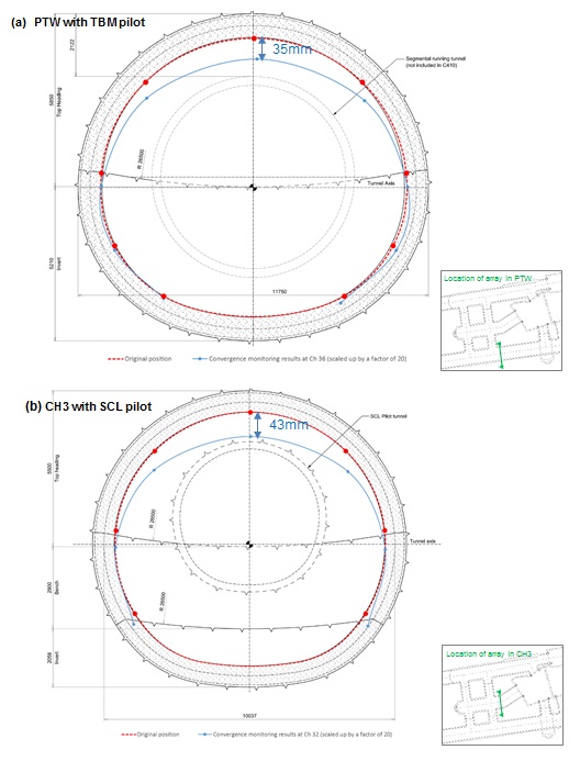
Figure 16 – Convergence monitoring results for PTW and CH3
Surface movements and compensation grouting
Although surface movements were primarily controlled by compensation grouting, there was also scope to control movements by amendments to the excavation sequence. Ground movements reduce significantly once the SCL ring is complete and so early ring closure was preferable in this regard. However the benefits of achieving earlier ring closure needed to be balanced against the risks associated with a shorter invert providing less support to the face.
This approach was successfully deployed at Bond Street when a noticeable increase in ground movements was observed during excavation of the westbound platform tunnel. This was mined from east to west from AP3A wraparound; tunnelling commenced from AP3A using a 4/2 sequence, and Figure 17 shows the settlement of the tunnel crown and the ground surface directly above the tunnel crown as tunnelling commenced in red.
After approximately 120m of tunnelling, the observed ground movements were seen to increase significantly. This is not evident from the surface settlements shown in Figure 17 because these settlements also include the effects of subsequent compensation grouting, but can be seen in the sudden increase in crown settlement between 120 and 135m along PTW. Following a review it was agreed that the stagger in the excavation sequence could be amended from 4/2 to 3/1 from 135m onwards, thereby reducing the distance between the face and ring closure by 1m. The data for this part of the sequence is shown in blue in Figure 17. It can be seen that there is an immediate reduction of over 5mm in the crown settlement arising from the earlier ring closure, although as excavation progressed further westwards a trend for increasing crown settlements was observed.
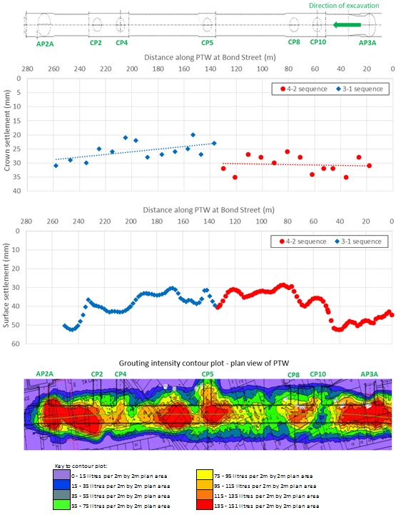
Figure 17 – Variations in observed lining behaviour and ground response along the length of PTW at BOS
The surface settlements are broadly consistent for the two sequences, due to the effectiveness of the compensation grouting however the grouting intensity – defined as the volume of grout, in litres, injected within a 2m by 2m grid in plan – required to achieve this is higher above the western part of the tunnel, where the 3/1 sequence was used. At the very west end of the tunnel the relatively high grout intensity and ground movements are thought likely to be a result of the excavation of the adjacent western ticket hall box as well as the tunnel excavation, and possibly also variability in the superficial deposits in this area.
The differences in behaviour along the length of PTW are considered likely to be a function of the changing ground conditions at and above the tunnel horizon. PTW was excavated entirely within the London Clay formation, in the A2 and A3 units. The variation in the levels between these is shown in the geotechnical long section in Figure 18. For every advance the undrained shear strength, cu, was tested using a pocket penetrometer. For safety reasons these tests were undertaken on the spoil and so may not be representative of the in situ clay properties, but the tests give a useful index of variability. Figure 18 shows the variation in average undrained shear strength recorded in the top heading excavation rounds, along PTW.

Figure 18 – Recorded ground conditions during excavation of PTW at Bond Street
There is a clear reduction in undrained shear strength in the central part of the tunnel near CP5, corresponding with the location where the higher crown movements were observed and the sequence adjusted to successfully compensate for this.
Other factors that could potentially influence the ground and lining response include the advance rate, and the early age strength gain of the shotcrete. Figure 19 shows the advance rate during enlargement of PTW. These were reasonably consistent, apart from the first part of the drive, due to this being the first enlargement from a segmental pilot to be undertaken at Bond Street. Given the general consistency it is not thought that the advance rates for PTW would have any significant influence on any differences in the observed behaviour as tunnelling progressed. Similarly the early age strength gain of the shotcrete was also generally consistent during tunnelling across all C300/C410 sites and tunnels and so we cannot quantify the effects of variations in this.
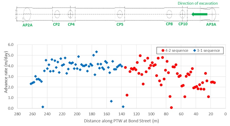
Figure 19 – Advance rates during excavation of PTW at Bond Street
7.0 Conclusions
The BFK initiative to submit an alternative “TBM first” tender submission was a key factor in the Client’s decision to award them the combined C300/C410 contract. This provided benefits to both the TBM and SCL teams, de-risking the programme and providing continuity of work for both tunnelling disciplines. Allowing the TBM to pass through the stations first presented the SCL team with a large diameter precast concrete pilot tunnel which could be rapidly, safely and effectively enlarged to full platform size using sprayed concrete linings whilst minimising noise, dust and vibration. Rapid ring closure and high production rates also enabled the team to deliver significant reductions in settlement [see Figure 20].
The initiative also delivered significant cost benefits of in excess of £80m, and programme benefits of 7 months. This also eliminated the need for 50,000 lorry movements through central London. The continuity of work offered by this solution permitted BFK to source, up-skill and retain key specialist labour and resource through the contract period in an over-stretched specialist market.
Despite a number of detailed technical challenges, which were successfully overcome, the works have been successfully completed safely, on time and on budget. Compared with the original reference design, the BFK alternative has delivered substantial benefits for the Contractor, Client and Stakeholders alike, and a similar approach could provide benefits to other projects in the future.
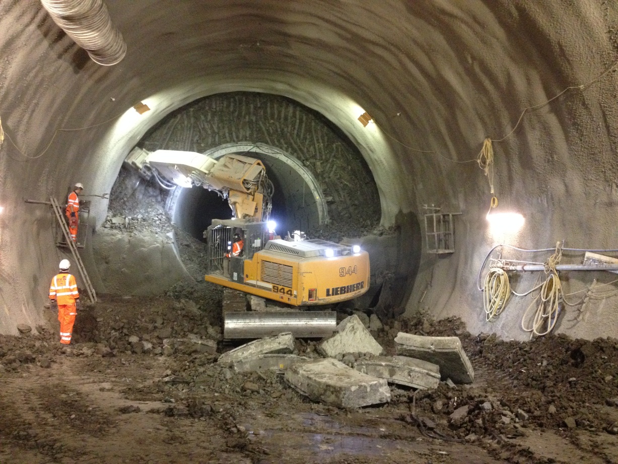
Figure 20 – Excavation of top heading during enlargement of precast concrete pilot tunnel to full platform size (11m wide x 10m high).
8.0 References
[1] Crossrail (2007). Crossrail Information Paper D12 – Ground Settlement.
[2] Crossrail (2007). Crossrail Information Paper D23 – Sprayed Concrete Linings.
[3] Crossrail (2014). Best Practice Guide: SCL Exclusion Zone Management.
[4] Davis, E.H., Gunn, M.J., Mair, R.J. & Seneviratne, H.N. (1980). The stability of shallow tunnels and underground openings in cohesive material. Geotechnique 30, No. 4, 397-416.
[5] ICE (1996). Sprayed Concrete Linings (NATM) for Tunnels in Soft Ground, an ICE Design and Practice Guide. Thomas Telford Ltd
[6] HSE (1996). Safety of New Austrian Tunnelling Method (NATM) Tunnels: a review of sprayed concrete lined tunnels with particular reference to London Clay.
[7] HSE (2000). The collapse of NATM tunnels at Heathrow: A report on the investigation by the Health and Safety Executive into the collapse of New Austrian Tunnelling Method (NATM) tunnels at the Central Terminal Area of Heathrow Airport on 20/21 October 1994.
[8] St.John, A.M., Pickett, A., Kendall, A., Potts, V.J. & McGirr, D.F. (2014). Delivering a safe integrated SCL design: The challenges and successes of Crossrail Contract C300/C410. Proceedings of World Tunnel Congress 2014 – 40th ITA-AITES General Assembly, Iguassu Falls, Brazil.
-
Authors

Adrian St.John, BEng (Hons) Eur Ing FICE CEng - BAM Ferrovial Kier
Adrian St.John is a Fellow of the Institution of Civil Engineers and a Supervising Civil Engineer. He has spent most of his 24 year career working on major infrastructure and tunnelling projects in the UK and overseas, including the Brighton Stormwater tunnel and High Speed 1 at St Pancras. He spent 6 years as Chief Engineer for BFK Joint Venture who were the main contractor on Crossrail contracts C300, C410 and C435, and is the Design Director for Carillion Eiffage Kier (CEK) Joint Venture bidding for the forthcoming HS2 main civil works.

Vicky Potts MA MSc PhD - Donaldson Associates Ltd
Donaldson Associates Ltd
Olivia Perkins MEng(Hons) - BAM Ferrovial Kier
BAM Ferrovial Kier JV
