Digging for monitoring gold: In-tunnel monitoring during the Crossrail Paddington Station box excavation
Document
type: Technical Paper
Author:
Harriet Rutledge, Stewart Harrison, ICE Publishing
Publication
Date: 07/09/2015
-
Abstract
This paper describes the approach taken to analyse, predict and monitor the behaviour of segmentally lined tunnels resulting from deep basement excavation directly above.
The Crossrail Paddington Station comprises a 24m deep box structure located entirely within London Clay. Prior to box excavation, twin 6.8m diameter segmentally lined tunnels were constructed through the box using tunnel boring machines (TBMs). Significant programme benefits were achieved by the concurrent use of the tunnels for TBM operations and excavation of the box to station concourse level, only 300mm above the as-built segmental tunnel lining. Reliable tunnel movement predictions and an accurate system of monitoring during the excavation were essential in order to ensure the stability of the tunnels and the safety of the operatives.
During the design phase, three-dimensional finite element analysis of the bulk excavation was carried out using Oasys LS-DYNA software. The model simulated diaphragm wall installation, tunnel construction and the staged top down excavation of the box. The model provided predictions of ground heave and tunnel ovalisation, which were compared against tunnel design limits.
The in-tunnel monitoring comprised a network of total stations and prism arrays providing real-time least-squares adjusted data. In order to take into account the tunnel environment and to achieve the required data resolution a design network with an error ellipse of 3mm and standard deviation of 1mm was created ‘virtually’ and analysed using Starnet Pre-analysis.
The monitoring system adopted advanced survey concepts in terms of networking and control; error was minimised and the data noise reduced by running the system as an organic network.
The in-tunnel monitoring produced real time movement data that could be clearly correlated with the box excavation activities. The observed tunnel behaviour showed good agreement with the numerical modelling results.
-
Read the full document
Notation
maTD metres above Tunnel Datum (Ordnance Datum + 100m)
OD Outer Diameter
TBM Tunnel Boring Machine
Introduction
Increasingly on large infrastructure projects, programme constraints require conflicting construction activities, often by different contractors, to be carried out concurrently. This was the case during construction of the new Crossrail Paddington Station in London.
The Crossrail Western Tunnels comprise twin-bored tunnels through central London constructed by tunnel boring machine (TBM). In order to meet a tight construction programme, a ‘TBM first’ strategy was adopted, whereby the tunnels were driven first and the stations were built around them, with the temporary rings broken out as the excavation advanced.
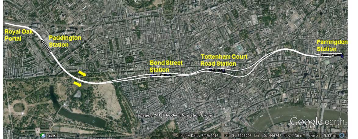
Figure 1 – Crossrail Western Tunnels Layout
The Crossrail Paddington Station box was located 880m along the 6850m twin bore tunnel drive from the Royal Oak Portal to Farringdon Station. Design stage programming suggested that waiting for the tunnel drives to be completed before excavation of the box would not only have significantly delayed construction of the station but would have resulted in delay to project completion. Similarly, as Paddington station was located so close to the start of the tunnel drives, completion of the box construction before commencement of tunnelling was not feasible.
The decision was taken to excavate the station box to concourse slab level, only 300mm above the tunnel crown, while TBM operations were ongoing beneath. This approach was adopted following a detailed assessment of the tunnel behaviour during box excavation, carried out using three-dimensional finite element modelling, which predicted maximum tunnel ovalisation well within the structural capacity of the lining.
In order to ensure the safety of both the Tunnelling Contractor and the Station Contractor, a real-time in-tunnel monitoring system was used. This allowed measured tunnel movements to be correlated with construction activities and compared to predictions. This observational approach was critical for the successful excavation of the box.
This paper presents the pre-construction numerical modelling and the design and implementation of the in-tunnel monitoring system. The monitoring results are presented and observed tunnel behaviour is discussed with reference to the predictions.
Paddington Station Box
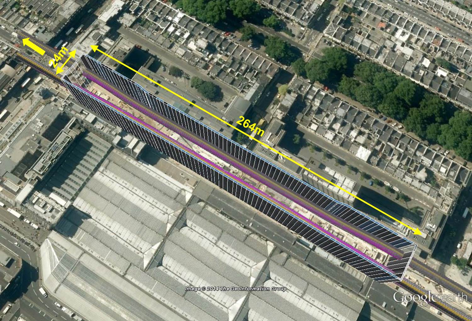
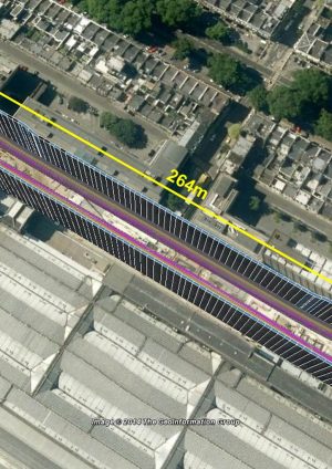
The new Crossrail Paddington Station is housed within a box structure 264m long, 24m wide and up to 24m deep. The box is ‘dog-bone’ shaped with wider ends for connection to the permanent bored running tunnels. The perimeter walls are formed from diaphragm wall panels, which extend 17m below the base slab.
Ground conditions at Paddington comprise approximately 5m of Made Ground and River Terrace deposits overlying approximately 70m of stiff over-consolidated clay (predominantly London Clay) underlain by Thanet Sand and Chalk.
The station layout is presented in Figure 2.
Figure 2 – Paddington Station Box and Tunnel Layout
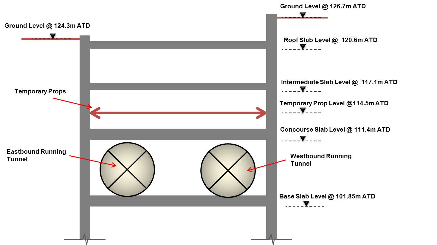
Station construction was designed to be top-down with four levels of slabs, roof, intermediate, concourse and base slab; although due to access constraints the intermediate slab was not constructed with the excavation but was delayed until after completion of the concourse slab.
The 6.8mOD bored tunnels were driven through the station box at a level between concourse and base slab. This was identified as being within the passive support zone for the diaphragm walls during excavation to concourse slab and, as the tunnel linings were much more flexible than the station walls, additional support was provided by means of a single row of temporary strutting.
The tunnels themselves were formed from 1.6m long steel-fibre-reinforced pre-cast concrete rings comprising seven normal segments plus key. The rings were connected by push-fit dowels; however, each ring was designed to be structurally stable, independent of the other rings.
A cross sectional view through the station and tunnels is presented in Figure 3.
Figure 3 – Station Cross Section
Tunnel Movement Predictions and Allowable Deformations
The assessment of tunnel behaviour during the station box excavation was carried out initially to review the feasibility of the concurrent excavation proposal and to allow any additional support requirements, for the station box or the tunnel linings, to be identified.
Modelling Approach
Tunnel movement and deformation was anticipated as the result of two different ground behaviours:
- Loss of overburden pressure above the tunnel causing ground heave. As the relative ground loss at the crown of the tunnel would be higher than at the invert, differential heave was expected to cause vertical ovalisation of the tunnel lining.
- Lateral deflection of the diaphragm wall panels during excavation of the box. With the tunnels located at the position of maximum deflection for excavation to concourse slab, the diaphragm wall panels were expected to apply high lateral loads onto the tunnel linings, causing further vertical ovalisation. This was of particular concern because, due to the narrow width of the box, there was only 95m clear distance between the eastbound and westbound tunnels and as little as 1.0m between the tunnels and the diaphragm walls.
As the overburden is removed above a tunnel, the lining becomes progressively more flexible (tending towards a mechanism). This was expected to increase the impact on the lining of the above behaviours.
Numerical analysis of the box excavation above the tunnels was carried out using the three-dimensional finite element software Oasys LS-DYNA with the constitutive BRICK model. The model considered a 5m wide section through the centre of the box, where the largest diaphragm wall deflections were expected and where the impact on the tunnels would therefore be greatest. The model boundaries were set at a distance of three times excavation depth beyond the back of the diaphragm wall and from ground level to the top of the Chalk (40m below the wall toe). The surrounding buildings were not modelled; however, the higher ground level on the south side of the box (adjacent to the westbound tunnel) was taken into account through the application of a 30kPa surcharge during the pre-excavation stages.
The station diaphragm walls and slabs were modelled using shell elements. Shell elements were also used for the tunnel segments (connected by interface elements) and the annulus grout surrounding the rings was modelled using solid elements.
The following construction sequence was adopted for modelling:
- Installation of Diaphragm Walls
- Tunnel construction at 107.2maTD – simulated through application of a 1% volume loss
- Excavation to the underside of the roof slab (120.6mATD)
- Construction of the roof slab and excavation to the underside of the temporary props (113.6mATD)
- Installation of the temporary props at 114.5mATD and excavation to underside of the concourse slab (111.4mATD)
- Construction of the concourse slab and removal of temporary props
All model stages were run using un-drained ground conditions.
Tunnel Lining Capacity
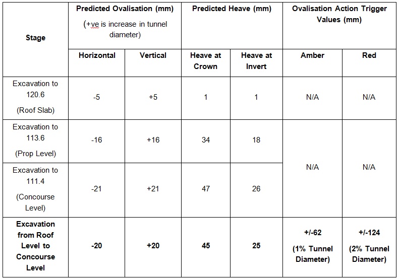
The tunnel lining design allowed for serviceability limit state ovalisation of 1% of the tunnel diameter (62mm), with ultimate limit state ovalisation expected to be greater than 2%.
Assessment Results
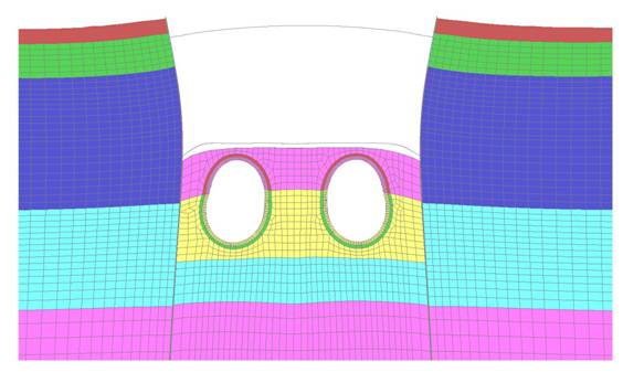
Figures 4 and 5 present the cumulative model and tunnel movements at the end of concourse slab construction. These clearly show the ground heave due to removal of overburden and the impact of diaphragm wall deflections on the tunnels:
- The majority of tunnel movement occurred due to excavation below roof slab; the model showed less than 5mm heave for the previous excavation stages.
- Maximum heave at invert level and crown level were approximately 26mm and 47mm respectively with resulting vertical ovalisation of 21mm.
- The horizontal ovalisation was non-symmetrical, with approximately 20mm inward movement of the tunnel lining on the diaphragm wall side and close to zero movement on the opposite side.
- The westbound tunnel experienced higher heave and ovalisation than the eastbound tunnel, reflecting the difference in existing ground levels.
These results were well within the structural capacity of the tunnel lining, confirming the feasibility of the concurrent excavation proposal.
Figure 4 – Model Deformation after Concourse Slab Construction (x50 Exaggeration)
Figure 5 – Tunnel Horizontal and Vertical Movement after Concourse Slab Construction
The tunnel design allowance and the model predictions were used to specify ovalisation action trigger values for the tunnel linings during excavation of the box. These are presented in Table 1.
Table 1 – Predicted Movements and Adopted Movement Trigger Values
No action triggers were imposed on heave (maximum or differential along the tunnel) as these did not affect the structural capacity of the lining and were not of concern for the ongoing TBM operations.
Instrumentation & Monitoring System Design
The aim of the in-tunnel monitoring was to produce real time movement data that could be directly correlated with the box excavation activities. In order to achieve this, the system at any point in time was designed to be better than +/-1.5mm in absolute position with 95% of the data being within +/-2mm resolution. The design of the system also needed to take into account the tunnel environment, in terms both of fixed obstructions and the regular construction train movements which blocked the signal.
As the predicted movements for excavation to below roof slab were very small, no monitoring was considered necessary for this stage. A survey of the as-built tunnel after excavation to roof slab, comprising a seven point array in every third ring, was used to calculate the existing ovalisation. Longitudinal sections at each point location were assessed for convergence against a best-fit centre calculation for the design tunnel ring (3.1m radius). From this a plot was produced showing how the convergence (change from design tunnel radius) varied along the tunnel for each prism position within the array and linear interpolation was used to produce a baseline convergence for each prism position within the system. The results showed clearly that prior to box excavation below the roof slab, the tunnel was squat 20-25mm vertically in the crown, with a horizontal divergence on each side of approximately half the magnitude of the vertical (i.e. existing ovalisation was in the opposite direction to that expected due to box excavation).
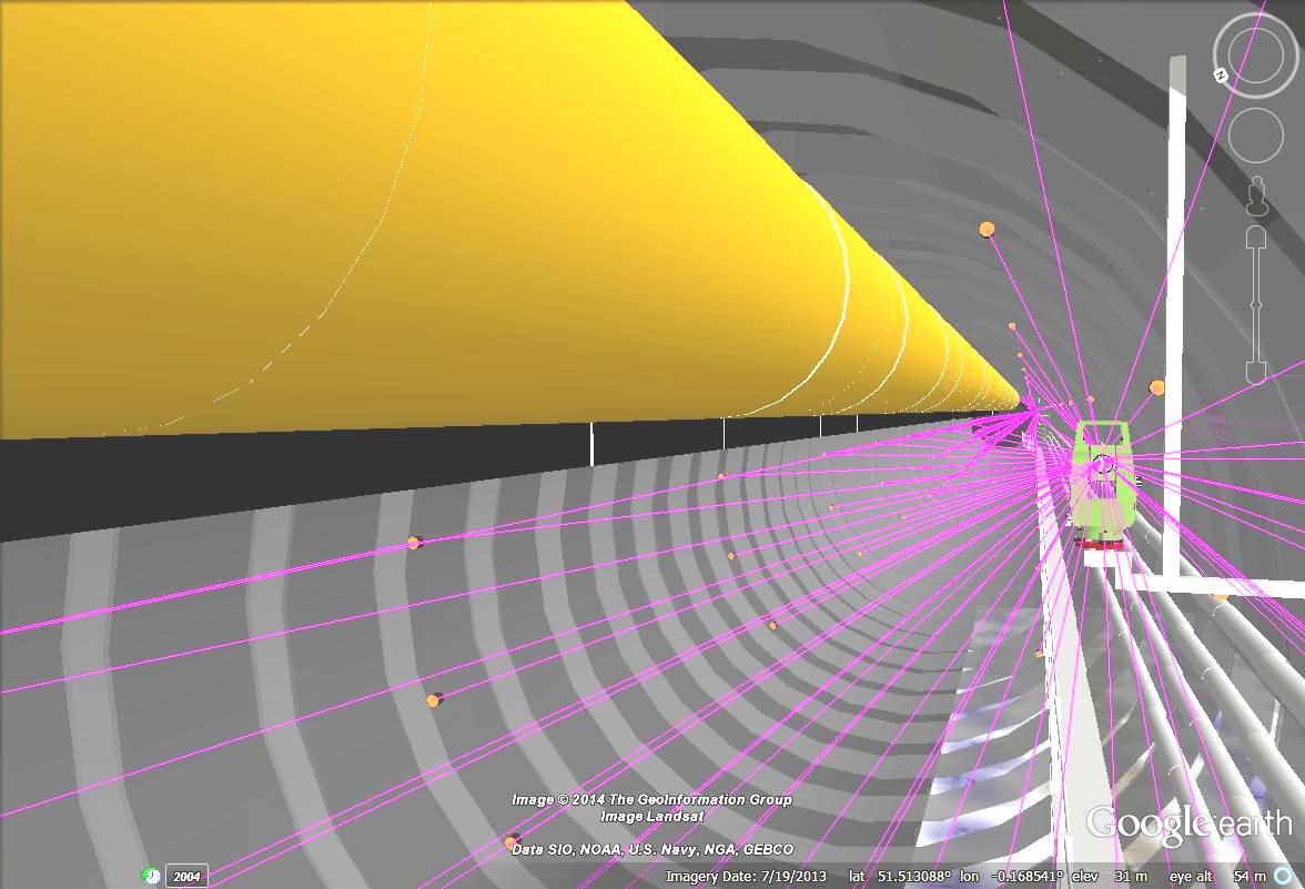
The in-tunnel monitoring system comprised a network of automated total stations within the zone of influence of the works, three in each tunnel, and prism arrays at five/six ring (8/9.6m) spacing. The monitoring points were designed at seven locations (A-G) in the ring profile, spread evenly whilst allowing for the position of the TBM construction equipment (ventilation bagging, railway tracks, walkway, fixed services etc.).
In order to take into account the tunnel alignment and physical obstructions, the instrumentation arrays were first modelled in a ‘virtual’ tunnel environment. As shown in Figure 6, this virtual modelling allowed the lines of sight from total station to prism to be reviewed and adjusted where necessary.
Figure 6 – Virtual Modelling of Tunnel Environment
To ensure that the system could achieve the required data resolution, the network was then analysed using Star*net Pre-analysis with error ellipses of 3mm and standard deviations of 1mm. This pre-analysis step was very important in the system design, allowing the predicted accuracy and precision of the results to be assessed. A further advantage of the pre-analysis design was to significantly reduce installation times within the tunnel, as it allowed the coordinates of the points to be set out and oriented correctly, hence minimising system snagging.
The system was designed to provide real-time least-squares adjusted data. This is a mathematical solution which interrogates all the data within a time period and returns the answer with the least overall error; it is used widely in setting up survey control networks. The data itself references areas outside the zone of influence of the works for stability and provides the ability to measure absolute movement (vertical / horizontal) of each point within the tunnel very accurately. The network’s least squares position was calculated on a trailing one-hour basis, which was considered an appropriate interval for the works because movements were predictable within this range and could be matched to construction activities. Reaction times within the system, the ‘real-time aspect’ are reduced to the speed of communication, only a few seconds.
The monitoring system adopted advanced survey concepts in terms of networking and control; error was minimised and the data noise reduced by running the system as an organic network. The organic network fixes points externally to the zone of influence of the works and partially fixes points within the zone of influence to the last known value, allowing those points to be used as control. This method stabilises the results, reducing system noise, and is calibrated specifically to follow the expected slow trending movements during the period of excavation and after. The calibration and tailoring of the network allowed the analysis to focus entirely on the aim of the system, to tie in the construction works directly and accurately with the movement of the affected structure.
Construction Control
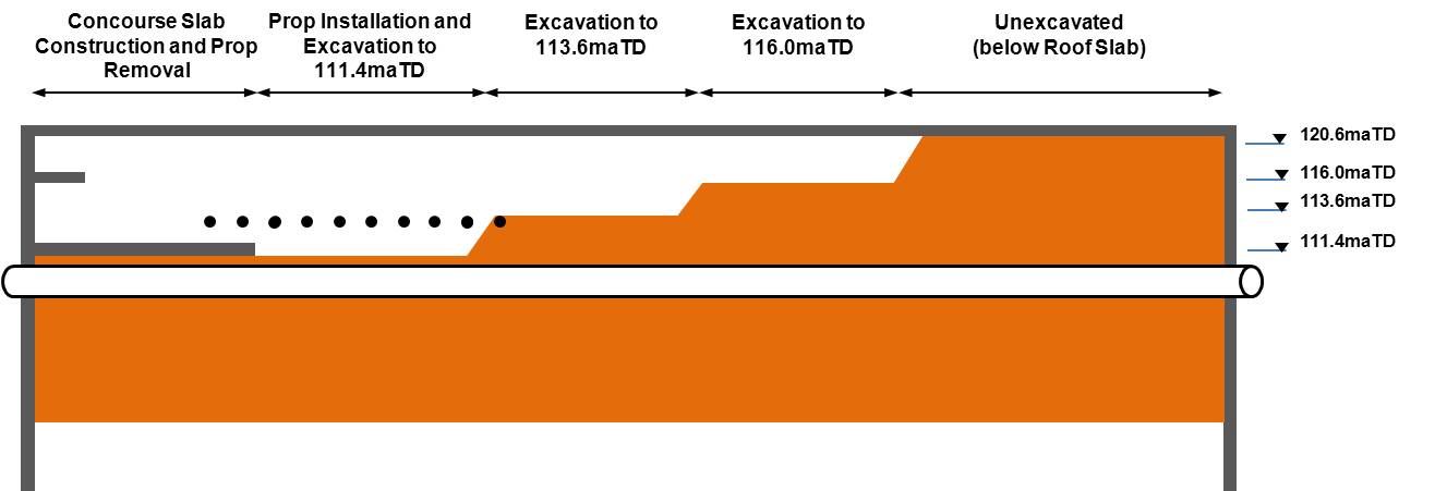
Figure 7 shows the staged construction process adopted for excavation below roof slab. Construction was generally from west to east along the box although excavation advances on either side of the box (i.e. above the eastbound and westbound tunnels) were typically staggered. The durations that different parts of the box were at each level, and the time between excavation and casting of the concourse slab in each area, varied widely.
Figure 7 – Station Box Excavation Sequence
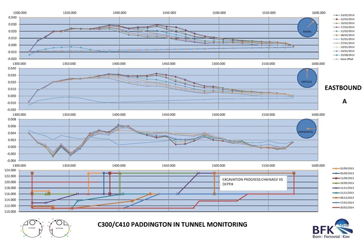
In order to match the in-tunnel monitoring results to the works, daily movement reports were needed and were automatically generated alongside mapping of the works. Figure 8 presents a typical daily report sheet; these were produced for each of the seven monitoring points in the eastbound and westbound tunnel arrays.
Figure 8 – Sample Daily Report Sheet (Movement Time Plots vs Construction Activity)
The monitoring data was actively used throughout the station excavation to review and adjust constraints on the length of box permitted to be left open at concourse level before the slab was cast. Back-analysis of the data, and particularly review of the rate of heave, also allowed the monitoring system to be decommissioned and removed from the tunnels before completing the concourse slab installation; this was necessary to meet the tunnel handover programme.
In addition to the automatic monitoring, daily inspections of the tunnel lining were carried out for all areas where box excavation works were taking place below level 113.6maTD (less than 3m above the tunnel crown). This was to identify any signs of distress in the lining; spalling of segment joints, crack propagation etc.
Monitoring Results and Discussion
Box excavation from roof slab to concourse slab level was successfully completed; tunnel distortions were well within the lining capacity and no distress of the lining was observed during any of the in-tunnel inspections. Details of the tunnel behaviour and a comparison with the predicted movements are provided below.
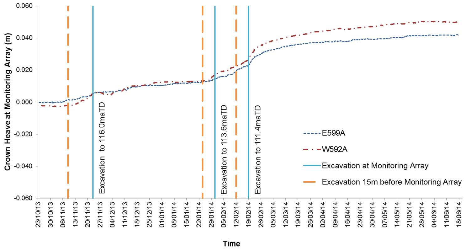
Figure 9 presents the change in heave with time measured along the crown of each tunnel (Point A). The 50mm maximum heave observed in the westbound tunnel correlated well with the predicted heave of 47mm. The consistently lower heave observed in the eastbound tunnel, which reflects the behaviour predicted by the numerical modelling, is attributed to the lower existing ground levels on this side (hence lower diaphragm wall deflections). The box end effects are also well defined, with heave at the end walls tapering to zero over a distance of 30m equivalent to three times the excavation depth.
The heave profile (which can be seen in Figure 8) also shows clearly the relationship between excavation activities and resulting ground movement; the wave of tunnel heave moving from west to east as the excavation moves forward.
Figure 9 – Change in Tunnel Crown Heave with Time (Longitudinal Plot)
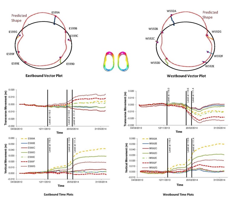
Tunnel ovalisation was not measured directly but was calculated as a function of the horizontal and vertical movement of each point within the tunnel array. This was tracked by means of vector plots and time plots for each point, both of which are demonstrated in Figure 10.
The time plots provide an overview of the movement with time of every point within a monitoring array. The effect of excavation above the tunnels can be seen to occur simultaneously at each point in the ring. As predicted by the numerical analysis, the tunnel crown experienced the most vertical movement and the invert the least. Similarly, the highest horizontal movements were observed at the points installed on the side of the tunnel closest to the diaphragm wall, with all points moving inwards, towards the centre of the tunnel.
Typical vector plots, taken from monitoring arrays near the centre of the box, have been overlain on the tunnel shape predicted by the numerical modelling. The actual tunnel deformed shape is very similar to the predicted, with the eastbound and westbound tunnel shapes almost mirror images of each other. The presence of the joints within the segmental lining results in a non-smooth profile, and the effect of the diaphragm wall deflection can be seen in the skew of the shape (distorting upwards and towards the centre of the box).
Figure 10 – Predicted vs Actual Tunnel Movement
The data quality was very good with standard deviation of 0.1mm 95% +/-0.2mm. This was consistent with the sub-millimetre accuracy predicted during the pre-analysis stage. No filtering or smoothing of the data (post-processing) was required, providing validation of the design approach.
The sensitivity of the system can be seen by a close study of the monitoring data during a period of excavation. Figure 11 presents the movement of adjacent crown points in the eastbound and westbound tunnels over an eight month period, during which excavation from roof slab to concourse slab was carried out in three distinct stages (excavation levels at 116.0, 113.6 and 111.4maTD). In the graph it can be seen that for each stage the monitoring detects the influence of the advancing excavation face, followed by a more rapid change when excavation is carried out directly above the array and a longer period of slowing movement which represents the ongoing heave at approximately 7mm/month.
Figure 11 – Sensitivity of System to Movement
During operation of the system continual review of the monitoring, especially the data quality, gave confidence in the results; in particular, that any excavation works within the box could be detected in the data. The accuracies and resolution of the system were further seen in the independent cross-check between the tunnels; the two systems (one in each tunnel) were run independently showing perfect symmetry in movement direction and reaction to works above.
Conclusions
The excavation of the Crossrail Paddington Station box, 24m deep and, 264m long, was successfully carried out only 300mm above of the crown of two large diameter segmentally lined tunnels. Most importantly, the concurrent excavation of the station box with the tunnelling operations resulted in an estimated programme saving of 10 months for the station construction (based on actual duration between start of excavation below roof slab and tunnel handover).
These concurrent activities were made possible by the use of detailed numerical modelling to predict behaviour of the tunnel linings coupled with real-time monitoring of the tunnel movements during the works.
The focus on monitoring system design and data quality, along with the implementation of an organic network, allowed movements to be monitored with very high precision. Development of a clear procedure and statistical analysis of the system itself produced results well aligned with the aims of the monitoring; to produce real-time movement data that could be clearly correlated with the box excavation activities. The monitoring of instrumentation within the zone of influence was controlled in a clear and scientific way – the organic network and its calibration was the key factor in delivering the high precision required.
Interpretation of the monitoring data and comparison with the predictions from the pre-analysis enables the performance of future systems to be assessed. In particular, this allows the design of organic network settings to monitor different types of movement.
This case study also provides valuable data on the behaviour of segmentally lined tunnels due to deep basement excavation. The actual ground and tunnel behaviour as observed by the in-tunnel monitoring showed good agreement with the design stage predictions and clear correlations could be made between the monitoring trends and the excavation activities which, as in the title, is monitoring gold.
-
Authors
Harriet Rutledge
Arup Atkins Design Team (Atkins)
Stewart Harrison
Bam Ferrovial Kier Joint Venture (Kier)
