Earthing and Bonding
Document
type: Technical Paper
Author:
Malcolm Anderson BEng(Hons) CEng MIET, Neville Leary FIET, Jonathan King FIET, ICE Publishing
Publication
Date: 09/07/2018
-
Read the full document
1 Introduction
Crossrail is building a new railway for London and the South East. It will be known as the Elizabeth line when it opens through central London in December 2018. The complete railway will run from Reading and Heathrow in the west, through 42km of new tunnels under London to Shenfield and Abbey Wood in the east. The project is building 10 new stations and upgrading 30 more, while integrating new and existing infrastructure. New state-of-the-art trains will carry an estimated 200 million passengers per year.
1.1 Civil and Systems Overview
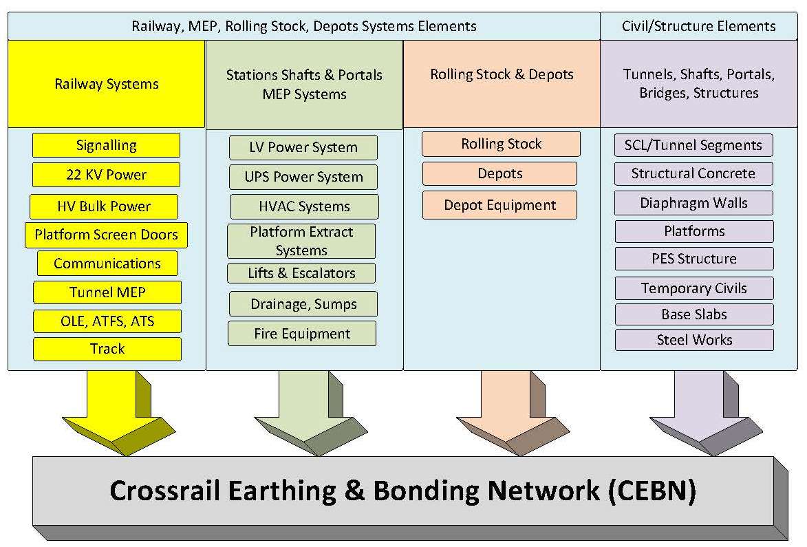
Crossrail has a vast amount of railway, mechanical, electrical public heath (MEP), depot equipment, and rolling stock systems. These systems must contribute to an economic, safe and suitable Crossrail Earthing and Bonding Network (CEBN). The project has undertaken an array of construction such as tunnels, surface/subsurface stations, intermediate shafts, portals, cross passages and bridges. This has brought about a considerable number of construction techniques, programme alignments, stages, such as energisation and contract delivery types which all contribute to the project complexity. Therefore the CEBN challenge was not only delivering a safe CEBN for the recognised systems but also the large civil elements which make up the majority of the project. The CEBN had to cover all scope which was new and unique in the UK, i.e. an underground metro style 25kV high capacity service. Crossrail is a new railway, built on new and existing assets and areas in a much built up urban environment in London. This includes an already operational complex AC/DC railway network. Figure 1 presents systems and structures which the CEBN had to cover.
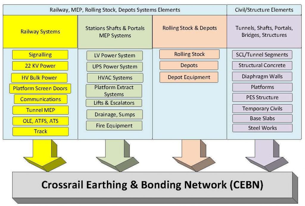
Figure 1 – Scope for Crossrail Earthing & Bonding Network
1.2 CEBN Development
To cover programme critical systems and structures E&B information needed to be provided early to allow the project to progress. These early type documents (strategy and philosophy) were provided by the Systemwide and Rolling Stock consultant (SRC – a rail specialist designer). They were implemented to allow the project to establish a common and correct approach to E&B. The strategy concentrated on covering railway, MEP, depot systems, and construction, where the philosophy on the practical applications and solutions. The documents included calculation methods, principles and options for the CEBN to be established.
Specialist studies were also required for further development of the CEBN for both strategy and to confirm design intent. One specialist study engaged the Earthing design of the autotransformer feeder station (ATFS) and autotransformer site (ATS). Results offered the earth system resistance (ESR), mesh voltages, earth potential rise (EPR), step voltage, and reference design of the earth mesh and or rods. Calculated mesh, earth potential rise and step voltages were shown below 670V for a fault clearance time of 200ms. The other specialist study required concentrated on traction power and E&B for the central section. This included all traction system conductors, non-traction systems conductors and the earth mats of the SSP and supply points. (i.e. negative feeder, contact wire, aerial earth wire (AEW), traction earth wire (TEW), rail, ROC (rigid overhead conductor), platform screen doors (PSD), bonding, leaky feeder, high voltage cable armouring, fire main, hand rail, etc. This study concluded two main compliance items to the BS EN 50122-1;
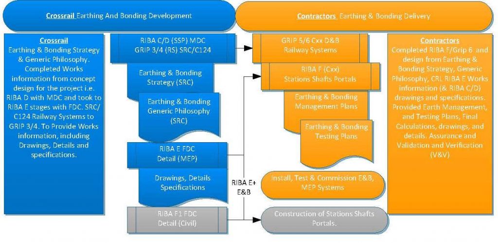
Figure 2 – Crossrail and Supplier E&B Document Delivery Process
- Accessible touch voltages for normal conditions to meet 60V permissible – Earth mat resistance value required is below 1Ω for SSP, SATS and ATS, and ATFS below 0.5Ω, for compliance. Induced voltages on the leaky feeder, platform screen doors (PSD) and fire mains are within 60V.
- Touch Voltages under traction short circuit conditions to meet the permissible 645V – As above for Earthing resistances and Induced voltages on the (PSD), leaky feeder and fire mains do not exceed the permissible touch voltage of 645V.
Crossrail developed design via multidiscipline and framework design consultants MDC and FDC respectively, to progress integration of E&B. Crossrail engaged SRC to develop railway systems design via GRIP process to GRIP (3/4) for the Railway Systems contractors (C6xx). A common component team was formed (C100) to establish common design criteria at the stations. Figure 2 illustrates an overview of how the documents and thus CEBN were integrated.
1.3 Crossrail E&B Strategy Scope
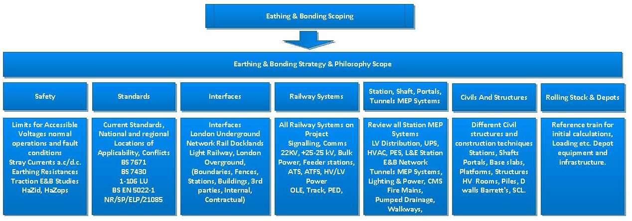
The E&B strategy scope covered principles and applicable standards to follow and which area of the project they apply i.e. station, shaft, tunnel (see figure 3). Crossrail is fundamentally different to a London
Underground (LU) or a Network Rail (NR) project, and the integration of the operators added complexity. The thinking was to provide a set of rules from the standards currently practised in UK railways. The CEBN needed to encompass these standards, legislation, current and best practice with support from calculations and modelling studies enabling earthing resistances and strategy to be further established.
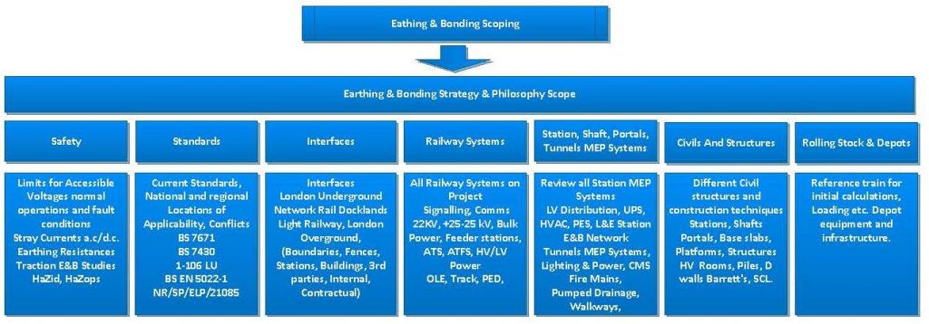
Figure 3 – Crossrail Earthing & Bonding Strategy Scope
It was recognised that there was an absence of a national standard for E&B of 2 × 25kV autotransformer (AT) system and/or guidance on the E&B of services in tunnels, stations, shafts, portals, workshops and depots. Therefore, decisions needed to be on rules applicable for Crossrail which reconciles the various requirements and standards of the various services in stations and in tunnels. This could have been achieved by extending either BS EN 50122-1 or NR/SP/ELP/21085 to include and E&B guidance notes for a 2×25 kV AT system in open air and in tunnels. Extension to the standards was not undertaken and thus the existing developed strategy and philosophy documents were used as the rules for CEBN requirements on the project.
1.4 Crossrail E&B Strategy Overview
One of the main principles of the E&B strategy was to endeavour to separate as much as practical the traction and SPP earth. This principle was to discourage traction fault current from using SSP equipment as practicable and return via the intended traction return system components. The traction fault current should return via its intended path back to its source i.e. ATFS. This strategy was also taken as SSP items are not all rated for this current and to reduce any touch voltages in the public and SSP maintenance areas which may arise under fault conditions. Although they have been modelled and no touch voltages were outside the permissible, under BS EN 50122-1 as already stated.
The E&B Crossrail interface to other railways is a large subject which is discussed briefly in section 4 herein. This was covered in greater detail in a previous paper dedicated for E&B interfaces with other railways on Crossrail. (See reference [4] for additional information).
The E&B strategy at SSP and to tunnels is shown in figure 4. This illustrates how the strategy is integrated into a design at a station and its interface which show the E&B components.
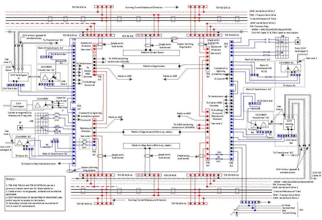
Figure 4 – Station Typical Earth System
2 Earthing in Stations, Shafts & Portals (SSP)
2.1 Background
As already stated the strategy is to keep SSP earth separate from traction earth, except for a single point dual cross bond at each SSP location. Earth rings and mats are provided at each SSP to ensure earth impedance is kept relatively low. Also for the purposes of redundancy and testing i.e. one connection can be broken and systems can continue to operate normally. Earth bars (EB) are installed in plant rooms for bonding of SSP equipment and metalwork and bonded back to the SSP Earth ring. The transformers have a delta star configuration, with the star point earthed to the station main earth terminal via the neutral earth link. Figure 4 provides a typical schematic of the E&B systems for a Station and is similar for Shafts and Portals.
2.2 Stations Surface and Subsurface (Boxed and Mined)
Major surface stations are typically constructed upon piled foundations, and it is these piles that form the earth network. Box stations are close to the surface and built from the top down. The structures are formed by either diaphragm walls or contiguous piles for the perimeter and plunge piles. Once perimeter walls were in place the interior of the station is excavated and a copper tape (mesh) is laid and a reinforced concrete base slab is installed on top. See figure 5.
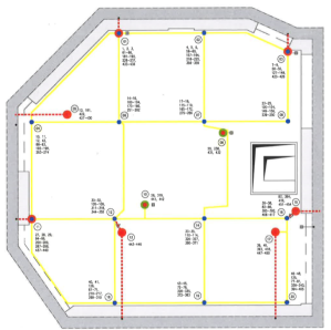
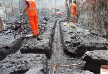
Figure 5 – SSP Mesh Design & Install below base slab
The plunge piles are then connected together along the length of the station to form one common earth mat. Earth mat leads are then brought out of the base slab to main station earth bars. Diaphragm wall sections and piles are allocated to various functions. Some are dedicated to SSP earth, some are dedicated for over site development (OSD) earth and others are dedicated lightning down conductors. Mined stations platforms are deep approximately 40/50m below street level. The method of construction is to sink a shaft at either end of the station and then form platform tunnels by mining between them. The shafts are formed as box stations. The platform tunnels are formed using sprayed concrete lining (SCL), designed to be steel reinforcing bar free.
The mined stations have two earth mats one in each shaft. The two earth mats are then interconnected to ensure that the two shafts remain at the same potential. Figure 6 base slab and earth mat below under construction showing reinforcing approximately at -50m, and piles another 20m lower. The significant size and weight of the reinforcing cages in diaphragm walls benefitted the E&B. They were built in sections and stainless steel screw couplers were used to join the cage sections. The screw couples served to make very good electrical connections between cage sections. Lifting bans welded served to make good electrical connection between all vertical bars in the cage.
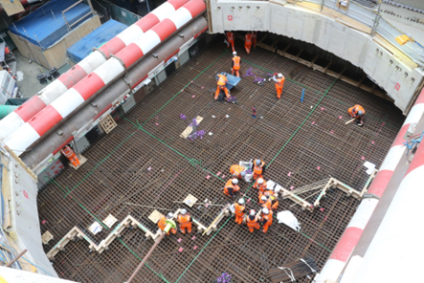
Figure 6 – SSP Base Slab
2.3 Earth Mats and Earth Mat Testing
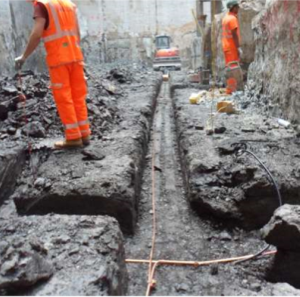
Earth mat connections are sized at 300mm2. This was firstly for maximum current carrying capacity and secondly for mechanical strength especially during concrete pours. It is vital that the earth mat cables are tested before and after concrete pours to make sure that continuity is maintained. See figure 7 for Earth mat and base slab connections.
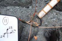
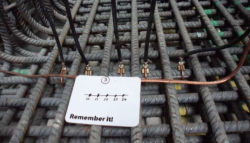
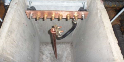
Figure 7 – Earth Mat and Base Slab Connections
The Crossrail method of testing earth mats is the fall of potential method 61.8% and slope test. At early construction stage this proved easier as individual structures were 40/60m in depth, thus test probes needed to be at 300m. Once stations became structurally interconnected they became over 300m long and then requiring probes at 2/3km, and this proved difficult. In central London gaining access to good quality open ground is uncommon, and establish good contact with the earth at some sites it was necessary to insert probes through tunnel linings. At outer locations it has also been difficult to obtain good contact with Earth due to land reclamation, ground and buried services. Typically Crossrail earth mat values are less than 0.06Ω which is significantly less than design and reference earth being used for the test. This did question the validity of the results in some locations.
2.4 Platform Screen Door and Platform Edge Screen
It was originally intended that platform screen doors (PSD) and platform edge screen (PES) form the separation boundary between traction and SSP earth. The PSD were designed to be traction earth so the PSD and train were at the same potential. The single point bonding ensured that traction return current did not flow through the PSD under normal operation. The PES is insulated top, bottom and both ends.
The overhead line equipment (OLE) is in close proximity to the PES and therefore flashover from OLE or the trains pantograph had to be considered. The design initially earthed the technology wall to the SSP and the floor of the smoke extract plenum to the traction earth. The inside of the technology wall was to be lined by insulated strike plates to prevent flashover reaching SSP earth. The PES structure had insulators that separated the traction earth from the station earth. The original concept can be seen in figure 8.
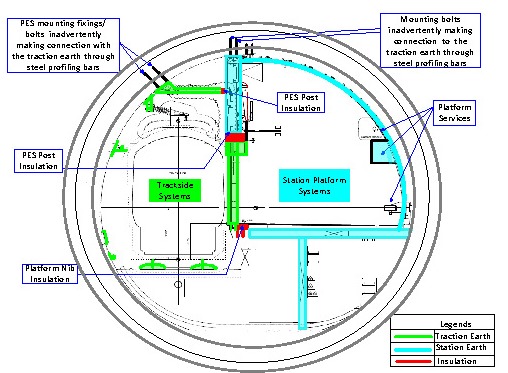
Figure 8 – PSD and PES Original Earth Concept Design
The PES design for the mined station was reliant on the SCL lining being metal rebar free, but it became clear steel rebar was present. This steel could easily bypass the insulation pieces in the PES and resulted in change to the earthing concept, which can be seen in figure 9. It was also decided to earth the PES structure at both ends to the traction return which attracted traction current to flow through the PES. The reasoning behind connecting the PES at both ends was to ensure a good electrical path in and out of the PES steelwork.
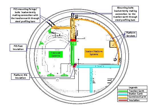
Figure 9 – PSD and PES Updated Earth Concept Design
The PES was modelled and results indicated that 20% of the traction return current could flow through the PES at Stations. E&B of the PES to traction did simplify the earth concept as it removed the need for insulators and flash plates. Having made appropriate changes to the PSD and PES, measures needed to be undertaken to prevent damage from traction current to platform SSP equipment. The final circuit protective conductors (CPC) and armour of the sub main cables serving platforms were bonded to traction earth. This allowed any fault paths generated from the station LV are to be returned to station earth via the traction earth link to the SSP. This followed the same configuration as the GL/GT1255 standard. This can be seen in figure 10.
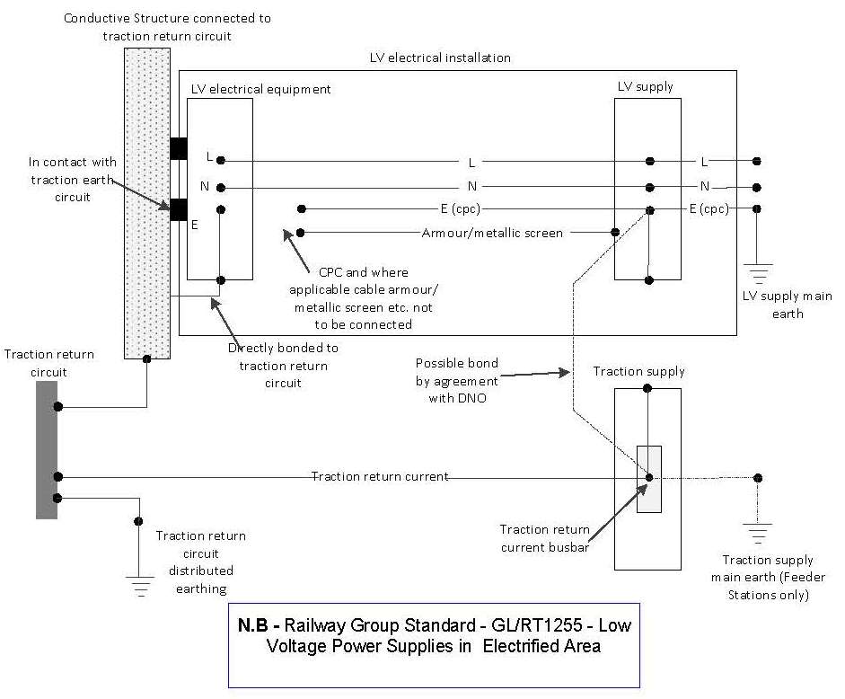
Figure 10 – Platform Services Earth Configuration
A similar view was taken for box stations as fixings could make contact with the steel reinforcing bar would bypass separation. Additionally this was compounded by the station equipment fixed into the same steel rebar as tunnel equipment, overriding intended separation zones.
3 Tunnel Earthing
3.1 Overview
The tunnels not only provide infrastructure for the passage of trains, but also act as a conduit for services that supply the railway systems from the SSP and the whole railway. The traction system within the tunnels relies on many of these systems. By design traction return current will pass through the following Tunnel systems;
- Aerial earth wires 1 & 2
- HV non traction cable armour/screen
- Running rails 1 & 2
- Traction earth wire at evacuation walkway level
- Linear cable trays & ladder racks
- Tunnel fire main
- -ve feeder cable screen
- +ve feeder cable screen
There are also other systems within the tunnels i.e. signalling & telecommunications (S&T) that are not designed to carry traction return current, and need to be provided with certain measures. This section will provide such details, and figure 11 illustrates a typical tunnel Earth arrangement.
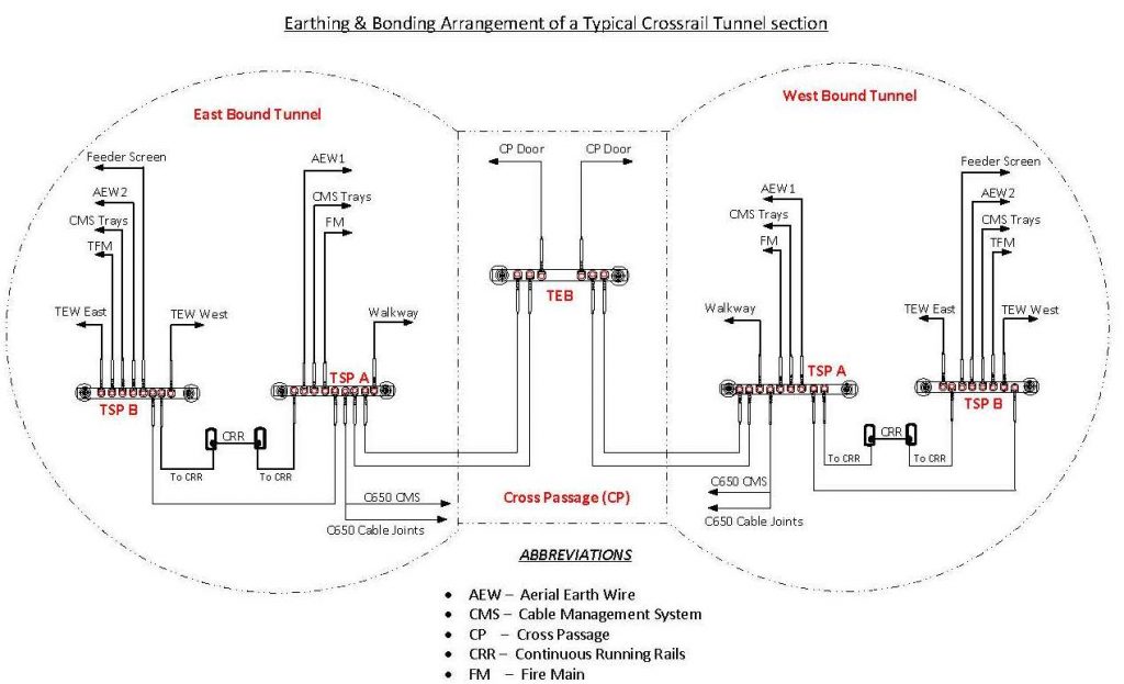
Figure 11 – Typical Tunnel Earthing System schematic
3.2 Tunnel Earthing System
The Tunnel E&B system interconnects the tunnel systems (above) via a series of conductors and EB within the tunnels. There are currently 800 EB, 740 are traction spider plates (TSPs) and 60 are traction earth bars (TEBs). TEB are located within SSP. For shafts & portals, these are normally closed (N/C). At stations there are two TEBs, one set of test links are N/C, the other normally open (N/O).
TSP’s are also located trackside at regular intervals in the tunnels and open route. For the surface section of the railway, self-bonds on each track are located at 500m intervals and a cross-bond between the eastbound (E/B) & westbound (W/B) at 1000m intervals. In the central tunnel section, this strategy is constrained by availability of cable routes between the E/B & W/B tunnels. Due to the location of SSP and cross passages, cross-bonds between the E/B & W/B tracks are fitted at distances ranging from 350m to 1000m.
The TEB within the cross passage receives dual 70mm² conductors from both the E/B and W/B tunnels. These conductors are connected directly to the TEB without test links so the traction earth system is common to both roads. Cross passage doors are located within the OLE zone so they each receive 70mm² bonds.
Power supplies for S&T are generally derived from SSP. Services that transition between SSP and tunnels are gapped with an insulating gland either at the SSP panel or the trackside cabinet. Trackside cabinets are bonded to traction earth and LV power cables bonded to SSP earth. This is achieved by an insulating cable gland at the point of termination to the cabinet in the tunnel. The non-metallic portion of the insulating cable gland shown in Figure 12, sandwiches the gland plate at the cabinet ensuring isolation between the two Earth systems.
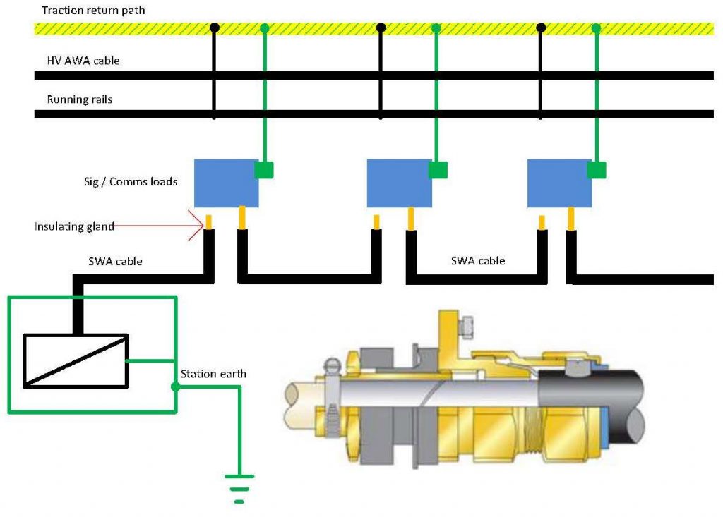
Figure 12 – Gapping & Bonding of S&C & Cable Gland
The gland is then securely protected with a heavy duty heat shrink sleeve. The equipment is then bonded to the TSP. Breaking the continuity of the cable armours down to short sections with each section bonded to traction earth reduces traction return current through the armouring or cable screen. Further supply cables that daisy chain from cabinet to cabinet are glanded in a similar manner ensuring all armouring are at traction earth, but the earth itself is formed from a series of radial earths. This ensures armours of S&C cables do not form part of the traction return path.
The non traction 22kV cables comprise 3x1c AWA (aluminium wire armour) cables and are jointed at the tunnel interface with SSP. Each joint has an earth braid connected to a local 4 way EB and is connected to TSP on the tunnel wall. The terminations to the 22kV switchboards are cross bonded, but gapped from the switchboard earth (figure 4 shows details of this around the transformer and HV switchgear).
Tunnel MEP such as pumped drainage, fire main and handrails are bonded to traction earth. This is typically at 500m intervals or at cross passages. Where the tunnel fire main enters the SSP it is gapped from the station fire main by using a 2m insulating section. Tunnel lighting and power panels (TLPP) are supplied from SSP. The sub-main feed to the TLPP is gapped at the gland plate by means of an insulating gland and protected by heavy duty heat shrink. The cables running from the TLPP to the tunnel plant are armoured. The cable armour is bonded to traction earth at its load end. For long runs, the cable armour can be gapped and bonded to traction earth. This creates a series of armours that are each bonded to traction earth, but no continuous path. Figure 13 shows this diagrammatically.
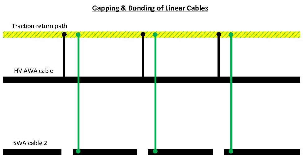
Figure 13 – Longitudinal Earthing in Tunnels
4 Interfaces
The Crossrail route has interfaces to other railways resulting in earth related issues. Where the interface is at 25 kV AC there are few issues other than sharing of return paths. Where interface occurs with third rail DC the earth on Crossrail (which is AC) is incompatible with a DC railway. The AC electrified railway has to connect infrastructure to earth for safety reasons, whereas DC railways require insulating rails from earth as far as practical to discourage stray current corrosion. Crossrail has as far as possible endeavoured to maintain separation to the North Kent line (NKL) and Docklands Light Railway (DLR) and cross bonded only where necessary. Prior to Crossrail energisation background measurements are being undertaken to benchmark existing stray current so that any change can be monitored.
The interface with LU stations is more complex. At station level it is impossible to separate the Crossrail and LU station earths as the structures and services are integrated. Therefore a decision has been made to cross bond the Crossrail main station earth to the LU main station to provide dedicated paths for stray current. This strategy endeavours to keep systems at the same potential.
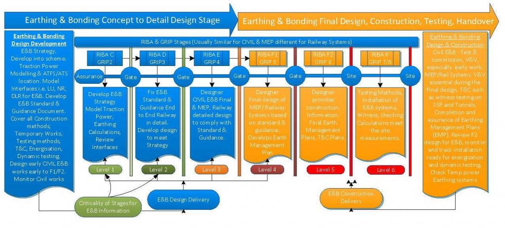
Figure 14 – E&B Project Life Cycle
Crossrail interfaces with the Central and Hammersmith and City Lines at a number of station locations. As a result the Central and Hammersmith and City Lines become parallel paths for Crossrail traction returned current. To control the flow of AC return current flowing in LU lines dedicated cables have been installed to provide fully rated paths that can be monitored so that change can be identified. This is of particular importance as 50 Hz AC currents can affect operation of some of the older signalling track circuits. Vulnerable circuits have been immunised based upon the findings of the traction power model.
During energisation the currents in the cross bonds between Crossrail and LU will be measured to ensure that the current flowing into the LU is no greater than predicted in the model and the signalling track circuit immunisation is effective.
5 Summary
It is noted that Crossrail has many challenges and E&B is no exception. E&B needs careful consideration to achieve safe and secure systems. This is from initial strategy from specialist studies to final detailed design through project integration and final construction and testing. Crossrail is in the construction and testing stages and there will be more E&B challenges to overcome until the final project handover. The paper has covered experience gleaned from the project so far. To complete the paper some lessons learned are offered below which could be considered in future projects;
- Projects could produce an E&B standard and supporting guidance. A standard would increase integration and ownership and help reduce variance. The scope of any standard and its supporting guidance should cover temporary work/power supplies and project stages i.e. energisation, dynamic testing etc.
- Keeping traction earth separate from SSP is suitable in concept. However, in practice it has proven very challenging to achieve 100% separation. Civil works can easily override E&B strategy i.e. steel in SCL and fixings to reinforced structural concrete which overlap different earth zones.
- When using structures as earth mats care must be taken. They should be tested immediately after installation as testing becomes difficult in urban environments when all the structures are connected and after the start of SSP mechanical, electrical and public health (MEP)/railway systems fit out. Reference rods could be adopted in the floor of a tunnel or cross passages in future for ease of test reference.
- The civil design and installation must be closely monitored for E&B design, installation, and testing compliance. Early civil works include earth mats and integrated earths such as diaphragm walls and piles i.e. for earth grounding and LPS.
- Keeping the earth gapping zone at the same location is difficult due to differing standards. However, a single earth gap zone at one location is more suitable for the long term maintenance for gapping cables from SSP to tunnels.
- Finally, Figure 14 illustrates some of the important E&B features obtained from experience on Crossrail and can be provided throughout the life cycle stage of any railway project. The figure highlights topics to focus on during each stage which need consideration to achieve a successful delivery.
Acknowledgments
Professor Rhys Vaughan Williams for his continuous support.
References
[1] BS EN 50122 Railway applications – Fixed installations. Part 1, Protective provisions relating to electrical safety and earthing.
[2] NR/SP/ELP/21085 Specification for the design of earthing and bonding systems for 25 kV electrified lines.
[3] British Standard BS 7430:1998 Code of practice for earthing.
[4] Power, A – Integration a Case Study – IET REIS 2013
-
Authors

Malcolm Anderson BEng(Hons) CEng MIET
Malcolm is the head of discipline for earthing and bonding in the Crossrail Chief Engineers Group since 2014. He is responsible for the earthing and lightning protection of all of the stations, shafts and portals as well as the running tunnels. He has under taken similar roles on the Heathrow Express, Terminal 5 Stations, Western Dedicated Freight Corridor in India, East London Line and Manchester Metrolink.
He entered the programme in 2009 as part of the design team for Liverpool St Station enabling works, and supervised the construction of the enabling works including relocation of a traction substation, and station electrical switch rooms. He then moved to a role as Head of Electrification for Rail for London for the Crossrail routes in 2013 and oversaw the review of electrification and EMC for the Crossrail Central Section.


Jonathan King FIET - Crossrail Ltd
Jonathan has been working on the Crossrail project from 2006, firstly as a Crossrail supplier MDC, and FDC and more recently for Crossrail as an Engineering Manager and Engineering Safety Manager. Jonathan’s responsibility has mainly covered systems design, delivery, construction, and safety engineering aspects.
Jonathan has been in the Railway Industry for nearly two decades, working on projects such as CTRL section 2, Thames Link and SSL 4LM. Jonathan is also undertaking research on the Crossrail project under a programme affiliated with the University of Birmingham (UOB) for Reliability, Availability, and Safety (RAMS) and Integration.