Mechanical Design Principles
Document
type: Technical Paper
Author:
Matthew David BSc CEng MIMechE MCIBSE, Steven Sheridan CEng, Stephen Turley MEng CEng MIMechE MCIBSE, Robin Underwood, Joseph Kanu, Joshua Milton, Annabella Conmee, ICE Publishing
Publication
Date: 30/09/2017
-
Read the full document
1. Introduction
This paper is written for use by the designers of Stations, Shafts and Portals.
The purpose of this paper is to clarify the minimum performance requirements for the design criteria, including temperature range and ventilation, for each room type and any particular system requirements.
With an agreed set of minimum performance requirements every opportunity will be made to:
- Drive out unnecessary complexity of installation.
- Drive out unnecessary complexity of operation.
- Gain more consistency of design and application.
- Reduce capital and operational expenditure
These principles should accompany a set of Mechanical Design Criteria.
The strategy at each Station, Shaft and Portal for cooling and ventilating, as developed by designers, and how each system is to be applied needs to address the minimum performance criteria required.
1.1 Design Priorities
The design of heating, ventilating and cooling of rooms should be as simple as possible. The following order of priority should be adhered to by designers when considering the systems to suit their specific railway facility when providing ventilation, heating and cooling:
- Natural ventilation for fresh air and cooling.
- Mechanical ventilation for fresh air and cooling.
- Heating
- Mechanical By:
- Central air system
- Refrigerant based system
- Chilled water system
Air systems may incorporate heat recovery and should be selected to maximise the efficiency of the recovery over a year. The order of priority in the selection should be:
- Plate heat exchanger.
- Thermal wheel
Run-a-round water coil systems are to be discouraged as they are complex to maintain and are less efficient than the other methods above.
2 Mechanical Systems’ Design
2.1 Contract Requirements
The high level Crossrail Programme Functional Requirements stated the following:
- The detailed modelling during design shall identify those assets critical to performance and shall provide regimes which identify how access to such assets for planned and reactive maintenance and renewals can be optimised.
- Where there are critical assets the design shall identify duplicate facilities and standby equipment required to meet the performance requirements for Crossrail.
- Design of Crossrail systems and equipment shall consider operational and maintenance tasks in all emergency and abnormal scenarios, as well as normal operations.
- All stations shall be designed to meet requirements of DfT Secure Station Scheme to enable future application.
- The reliability and availability of assets & systems shall be in accordance with the ONW RAM Plan [Ref. R.17] and Central RAM Requirements [Ref. R.18].
- The design shall minimise the number and impact of critical assets so far as is practicable where the cost/ benefit can be justified.
These are very high level and not specific enough for detailed design of the HVAC systems.
2.2 Current Design
The designs were developed to provide fresh air and cooling and heating for the following operating conditions:
- Normal Operation. This is the condition in which the station and railway are operating correctly without disruption to the transport of passengers.
- Emergency Operation. This is a condition of disruption caused by fire. The size and location of the fire will dictate the level of disruption. The primary criterion is life safety and the ability to evacuate people to safety. A secondary consideration is the need to limit the extent of disruption and the time to rectify it so the normal operation can continue.
- Critical Occurrence. This is a condition of severe disruption caused by the loss of both the A&B electrical power supplies.
The main design drivers are:
- Planning constraints (LOD limits)
- Environmental constraints (adjacent buildings etc.)
- Business continuity of sub systems
- Temperature control criteria
- Spatial allocation for plant
- Operation on failure of plant
- Operation during maintenance
- Operation during a fire
- Operation on loss of A&B electrical supplies.
- Capital Expenditure, CAPEX
- Operational Expenditure, OPEX
- Energy use reduction.
There are three primary systems which could be designed to satisfy these requirements as follows.
2.2.1 Chilled Water System
Chilled water fan coils or cooling units adjacent the room served with a water pipe distribution system connected to air cooled chillers in an outside environment. There would be more than one fan coil, a number of chillers and associated pumps and one metal pipe distribution system.
These systems are used for rooms where the temperature needs to be maintained with relatively small variation through the year e.g. 20oC minimum and 24oC maximum.
One or more fan coils serve a room. Where the cooling load is C then each active unit would have a cooling capacity of W.
W=C/N
The number of units designed for the room would be N or N+1 to meet resilience and redundancy requirements.
N+1 allows the system to continue to operate in the event of failure and maintenance of a single fan coil unit, a single chiller and single pump.
2.2.2 Variable Refrigerant Flow Systems (including single unit Direct Expansion (DX) and heat pump systems)
Variable Refrigerant Flow systems would have fan coil units in or adjacent to the room with a refrigerant pipe distribution and chiller/condenser units located in an outside environment.
These systems are used for rooms where the temperature needs to be maintained with relatively small variation through the year e.g. 20oC minimum and 24oC maximum.
One or more fan coils serve a room. Where the cooling load is C then each active unit would have a cooling capacity of W.
W=C/N
The number of units then designed for the room would be N or N+1 to meet resilience and redundancy requirements.
This allows the system to continue to operate in the event of failure and maintenance of a single fan coil in the room, a single chiller/condenser and one pipe system.
2.2.3 Central Air Handling Systems
Central air handling units would have ducted supply and extract air serving each room.
These systems are used for rooms where the variation in temperature through the year can be great e.g. 15oC minimum and 35oC maximum. However they are also used to maintain rooms with small variation of temperature.
One or more air handling units serve a number of rooms.
Two units would be designed to meet resilience and redundancy requirements. This allows the system to continue to operate in the event of failure and maintenance of a single fan and air handling component.
2.3 Other Air Handling Systems
There are other air handling systems which could be designed; for instance to supply fresh air only or to provide a specific air extract requirement. It is important to address each system when considering the operation in a fire alarm mode.
2.4 Benefit Analysis
A very simple benefit analysis is shown below in Table 1.
Table 1: System Benefit Analysis
System Performance Criteria Chilled Water Variable Refrigerant Flow Central Air Handling 1.Temperature control criteria Tight 3 Tight 3 Loose 1 2.Spatial allocation for plant Medium 2 Small 3 Large 1 3.Operation on failure of plant Resilient 2 Very resilient 3 Resilient 3 4.Operation during maintenance Resilient 2 Very resilient 3 Resilient 2 5.Operation during a fire Robust 3 Robust 3 Robust 3 6.Operation on loss of A&B electrical supplies Complex/ High electrical load 1 Complex/ medium electrical load 2 Simple/ medium electrical load 3 Total Score 13 17 13 2.5 Normal Operation
The needs of each room comprise some or all of the following:
- Fresh air
- Air filtration
- Heating
- Cooling
- Acoustics
- Pressure differential
- Ventilation
- Exhaust air
No room air humidity control is required. The humidity limits specified for equipment do not require control. Very low RH may occur in extreme winter conditions for short periods of time. High RH may occur in summer for short periods of time. Where mechanical cooling is applied this will reduce the high RH.
2.5.1 System Redundancy
System redundancy shall be applied as follows to Critical Rooms:
Table 2: System Redundancy
System Components Level of Redundancy Chilled Water Systems. Fan Coils/ Cooling Units N+1 Chillers N+1 Pumps N+1 Pipework distribution N Variable Refrigerant Flow Systems Fan coils N+1 Chillers/ Condensers N+1 Pipework distribution N+1 Central Air Handling Systems Fans and air conditioning unit components. Supply and extract. N+1 Ductwork distribution. Supply and extract. N 2.5.2 Critical Rooms
System redundancy, as the table above, shall be applied to all rooms, critical to the normal operation, as listed below.
- BAT – Battery Room
- UPS – Uninterruptible Power Supply
- ESR – Emergency Switch Room
- SER – Signalling Equipment Room
- SES-R – Signalling Electrical Supply Room
- CER – Communication Equipment Room
- SCR – Station Computer Room
- SOR – Station Operations Room
- MCC – Machine Control Centre
- FCR – Fan Control Room
- TR – Transformer Room
- SR – Switch Rooms
Where this is applied:
- The chilled water systems are designed with more than one chiller to provide redundancy in the event of failure and maintenance.
- The Variable Refrigerant Flow systems are designed with more than one chiller/condenser and associated refrigerant distribution system to provide redundancy in the event of failure and maintenance.
- The central air systems are designed with two supply and extract fans/ air handling units to provide redundancy in the event of failure and maintenance.
The duty/standby design is to satisfy normal operating conditions and provide resilience of cooling in the event of single-point-of-failure.
Other rooms do not require N+1 and shall be designed to meet the cooling needs of the rooms in the most practical way respecting the specification.
2.6 Emergency Operation
The Fire Strategy and Cause & Effect for each building provide the detailed description of what is to take place on fire alarm.
On a confirmed fire alarm the building is evacuated. There is no phased evacuation.
On a confirmed fire alarm, in the tunnel or train the railway is stopped and the tunnel and trains are evacuated. The Station is evacuated on fire alarm activation within the Station. The tunnel does not have a fire alarm system. A tunnel fire would be reported by staff or drivers.
In simple and general terms the following happens as Table 3:
Table 3: Fire Alarm Action on HVAC
Location of confirmed fire Commentary Action on HVAC system CHILLED WATER Variable Refrigerant Flow Central AHU In a Room. Fire dampers close. In-room cooling units stay enabled.
Other rooms are continued to be cooled.
Enable Enable Enable In a Corridor. Other rooms would continue to be cooled. Enable Enable Enable In a mechanical plantroom Cooling would stop to those rooms designed to be cooled by central AHU. Stays enabled. Stays enabled Disable if in AHU room In a public area The HVAC systems do not serve these areas. Enable Enable Enable In a tunnel or train The HVAC systems don’t serve the tunnels but do serve the fan rooms and fan control rooms Enable Enable Enable Other general supply and extract systems would be disabled.
2.6.1 Discussion
In many commercial buildings, on confirmed fire detection, HVAC air systems are in general disabled. This is done to prevent smoke migration through ducted air systems. This could happen even with fire damper protection to compartments. Of course fires are unpredictable!
The fire alarm system is being designed to reduce the incidents of false alarms. However these will occur.
The decision to continue to enable the HVAC systems, in a fire alarm, is dictated by the need of electrical and electronic equipment to remain functional in such a condition. It is realised that a fire is an extreme event. In such an event the temperature of the room in which the equipment is located can be allowed to rise beyond the normal operating temperatures. If the heat load of each piece of equipment could be established, under these extreme events, then calculations could be made to understand whether or not the room could dissipate the heat passively. Perhaps an alternative method of heat dissipation could be designed.
It is the Critical Rooms where ‘overheating’ is to be avoided. The maximum operating temperatures need to be confirmed with the equipment manufacturers. Typically these may be 40oC but other rooms can tolerate even higher temperatures.
It is because many of these rooms are deep in the ground, with no natural ventilation to outside or heat loss via the room fabric to outside, that makes them sensitive to ‘overheating’.
Should passive heat dissipation contain the temperature rise below the maximum operating temperature then the HVAC systems, and any ducted air system, could be disabled on fire alarm. This would provide less risk in the event of fire and ease the complexity and maintenance of the Cause & Effect strategy.
Some of the Critical Rooms have equipment and functions duplicated in another room. This is the case at Stations with, for instance, an East and West Ticket Hall. This is not the case for all rooms e.g. SER and SESR. However if there is such redundancy at a station then a fire at one end may allow the HVAC air system to be disabled, whilst the systems at the other end provide operational continuity.
One advantage of enabling the HVAC systems on fire alarm is that on a false alarm the systems are maintained operational and so no restart time interval is incurred.
The need to enable ducted air systems on fire alarm may drive them to be designed with ducting fully fire rated. The only advantage this gives is to protect the system if the fire were in a corridor. If the system were not fire rated then it could still operate in a fire event anywhere else.
Should the fire be in a corridor then depending on the severity of the fire, and in which corridor it is, the Variable Refrigerant Flow pipework, chilled water pipework and central air handling ductwork may fail (other services may fail too including cable distribution). This would occur irrespective of the level of fire rating provided, in which case cooling would fail to all the rooms served. Where there is non fire rated ductwork in a corridor the motorised fire/smoke dampers associated with that corridor would be closed on fire alarm. This need not be the case with a fire rated ductwork system. Variable Refrigerant Flow and Chilled Water systems may continue to run to cool rooms. A central air handling ductwork system, if fire rated, may continue to run to cool rooms for a finite period of time. However those rooms where the fire dampers have closed would not then be cooled.
It is important that the fire dampers have a good smoke seal. If the supply and extract air systems continue to run there will be a negative pressure sucking through the closed extract air damper.
The operation of the HVAC systems as a whole on fire alarm in the tunnel or on a train should be unaffected. All the systems can continue to be enabled in this case.
In some instances the Critical Rooms are cooled using Chilled Water or Variable Refrigerant Flow systems and so the need to enable ducted air cooling systems in a fire event does not apply.
The decision to be made is whether the risk of a fire occurring in a corridor demands that any ducted air cooling system be fire rated throughout its distribution. This risk was assessed, by Crossrail at an early stage of the design programme, to be so minimal as not to require any particular fire protection measures be adopted to mitigate for such an event.
If fire occurs in an AHU room then the system would be disabled. No cooling would be available to those rooms cooled by the air system. Many of the duty/standby Air Handling Units are not segregated and so a fire in the air handling room would stop the plant and air supply to the rooms would be lost.
If a fire occurs in a Chilled Water chiller room then the system could continue to be enabled. However the fire brigade may want all plant to be stopped in the room of the fire.
If a fire occurs in a Variable Refrigerant Flow chiller/condenser room then the system would continue to be enabled. However the fire brigade may want all plant to be stopped in the room of the fire.
What this shows is that there are different failure scenarios depending on the location of the fire.
Should fire occur in any room that requires cooling, the motorised fire dampers will close. The cooling systems may continue to run to serve the other, unaffected, rooms. Only operations associated with the room of the fire may be disrupted.
If the fire were in the tunnel or on a train then the Station systems would be unaffected. All the cooling systems could remain enabled. The rooms associated with the tunnel ventilation systems would be cooled.
It is suggested that air cooling ductwork not be fire rated throughout because the risk of fire occurring in a corridor or riser is very small. However fire rated ductwork may be applied to maintain compartmentation in lieu of fire dampers. The designers would need to assess each solution on the basis of cost, space-take, build-ability, maintenance burden and operational advantages.
On fire alarm it is essential that the lifts are taken to the designated landing position for escape or fire fighting access. In a fire this would be via the normal electrical supply. The heat load in the lift electrical equipment room/ lift control room would be minimal and no different from its normal operation. The lift contractor should confirm this load.
2.7 Critical Occurrence Operation
This scenario occurs with the loss of A&B electrical power supplies which then requires the building to be evacuated. In these circumstances only the life safety equipment needs to operate for an extended period up to 4 hours. It is probable that evacuation will be completed in less than 60 minutes. Only trained and specially equipped personnel would enter the station in such an incident.
Rooms that are critical to the life safety evacuation are as listed below.
- BAT – Battery Room
- UPS – Uninterruptible Power Supply
- ESR – Emergency Switch Room
- SER – Signalling Equipment Room
- SES-R – Signalling Electrical Supply Room
- CER – Communication Equipment Room
- SOR – Station Operations Room
- SCR – Station Computer Room
- LER – Lift Equipment Room
It is expected that all HVAC systems will come to a halt in such circumstances. There shall be no Uninterruptable Power Supply, UPS, system support to this HVAC equipment. Heat build up in the rooms will be dissipated by passive means. This should be calculated.
2.8 Secure Rooms
2.8.1 Introduction
There are several references within London Underground standards regarding the distribution of mechanical services and secure rooms.
The definition of a secure room was not described within the Crossrail Works Information.
Transport for London’s London Underground Rule Book 10 ‘Station Access’ (Issue 5, April 2014) contains a definition and states that the term ’secure equipment room’ applies to all types of signalling equipment rooms, including the following:
- Relay Rooms
- Interlocking Machine Rooms (IMRs)
- Floodgate Relay Rooms
- Train describer, dot matrix or positive train identification rooms
- Signal and Control & Information computer rooms.
- Communications Equipment Rooms,
- Tunnel Telephone rooms
- Telephone exchanges
- Station Computer Rooms (SCRs)
Maintenance staff that need to access the above secure equipment rooms are required to present additional certification to the Station Supervisor before they sign out the secure room keys.
Maintenance staff that need to access transformer rooms, and lift/escalator related equipment rooms are also required to present additional certification to the Station Supervisor before they sign out keys to these rooms.
Electrical switch rooms, Battery rooms and Uninterruptable Power Supply (UPS) rooms were once considered secure equipment rooms by London Underground but this is no longer the case.
The need to define a Secure Room in this way is so that when fire detection is activated even on a ‘first knock’ or alert basis then the fire dampers to the room’s fire compartment are closed.
2.8.2 Minimum performance criteria
The following are defined as Secure Rooms:
- SER – Signalling Equipment Room
- SES-R – Signalling Electrical Supply Room
- CER – Communication Equipment Room
- SCR – Station Computer Room
- TR – Transformer Room (Particular circumstances may dictate that fire dampers are not closed at ‘first knock’)
- SR – Switch Rooms. HV and LV
- Relay Rooms
- IMRs, Interlocking Machine Rooms
- Floodgate Relay Rooms
- Train describer, dot matrix or positive train identification rooms
- Signal and Control & Information computer rooms.
- Tunnel Telephone rooms
- Telephone exchanges
- BMS head end Room
- FOSC Room
2.9 Mechanical Services Passing Through Rooms
2.9.1 Crossrail baseline standard requirements
The Crossrail baseline standard clauses concerned with mechanical services within rooms are listed below:
London Underground Standard – EME-ST-01-018-A2 – Mechanical Services Design
2.03 HEATING, 2.03.01 General – No pipework is to pass through secure rooms or electrical switch rooms.
2.04 HOT WATER SERVICES, 2.04.01 General – No pipework is to pass through secure rooms or electrical switch rooms.
2.05 COLD WATER SERVICES, 2.05.01 General – No pipework is to pass through secure rooms or electrical switch rooms.
2.08 VENTILATION, 2.08.12 – No ventilation ductwork is to pass through secure rooms or electrical switch rooms.
2.9.2 Current Standards
Standard clauses concerned with mechanical services within rooms include:
LUL guidance document G-074 (which supports LUL Standard 1-068-A3 Mechanical Building Services, Utility Provision and Energy Management in London Underground)
Section 6: Air Cooling, 6.1.4 – All secure rooms where CCUs are to be installed should not be positioned above any permanently positioned equipment/cabinets/desks etc. It is preferred that CCUs are wall mounted.
2.9.3 Conclusion and recommendation
Pipework containing water under pressure within any electrical room could present a significant risk to equipment. The distribution of pipework within electrical rooms should be avoided. The distribution of condensate drainage pipework within an electrical room is permitted provided it is associated with the cooling units serving the room.
Ductwork passing through an electrical room is less of a risk, but within a new build environment any ductwork that doesn’t serve the room could potentially be taking up useful space at soffit level. Ductwork passing through a secure room that doesn’t serve the room also adds complexity to maintenance for duct cleaning and inspection. The risk concerns accidents that may arise when the cleaners are in the room. Routing ductwork through an electrical room should be avoided unless the ductwork serves the room.
As with any equipment room, including secure rooms, HVAC plant (AHUs, fans, refrigerant branch control units and FCUs) should not be located above equipment within the room. Malfunction of the plant presents a risk to the room’s equipment (condensate leaks) and a hazard for maintenance staff.
2.9.4 Minimum performance criteria
The following are defined as Electrical Rooms:
BAT – Battery Room
UPS – Uninterruptible Power Supply
ESR – Emergency Switch Room
SER – Signalling Equipment Room
SES-R – Signalling Electrical Supply Room
CER – Communication Equipment Room
SCR – Station Computer Room
LER – Lift Equipment Room
EER – Escalator Equipment Room
MCC – Machine Control Centre
FCR – Fan Control Room
TR – Transformer Room
SR – Switch Rooms. HV and LV
Relay Rooms
IMRs, Interlocking Machine Rooms
Floodgate Relay Rooms
Train describer, dot matrix or positive train identification rooms
Signal and Control & Information computer rooms.
Tunnel Telephone rooms
Telephone exchanges
FOSC Room
Routing ductwork through an Electrical Room should be avoided unless the ductwork serves the room.
HVAC plant (AHUs, fans, refrigerant branch control units and FCUs) shall not be located above equipment within the room. They should be wall mounted.
Pipework containing water under pressure shall not pass into or through an Electrical Room.
Pipework containing water not under pressure, including condensate water drain pipes under gravity or pumped from a small condensate water pump, shall not pass through the above rooms and, where the condensate is formed by equipment in the room, shall exit the room with as short a pipe length as possible to drain outside the room.
HVAC plant, of any kind, shall not be located within the following rooms:
- SER – Signalling Equipment Room
- SES-R – Signalling Electrical Supply Room
- TR – Transformer Room
2.10 Design Criteria Schedule
Specific limits, where applicable, for the minimum and maximum ventilation air flow rates, temperature and noise criteria for each room type are scheduled in Mechanical Design Criteria.
2.11 Guide to Equipment Room Ventilation
2.11.1 Purpose
Without expensive and time consuming computation fluid dynamics (CFD) software, calculating the ventilation requirements for a room is done using basic calculations which includes an additional margin. There can be a tendency to factor in too much margin due to uncertainty of the room airflow and its affect on the cooling of the room. The purpose of this extract is to highlight how various aspects of the room design can lead to more effective room ventilation.
2.11.2 Discussion
Effective room ventilation is vital to ensure that the critical and non critical equipment does not fail through overheating in equipment rooms. The efficiency of ventilation depends on effective removal of heat from the room and the total energy requirements of the supply and extract systems to achieve this. Parameters that influence the efficiency of the mechanical cooling in a room include [4]:
- Room shape and geometry (including projections)
- Position of the air supply terminals and grille geometry
- Air supply velocity
- Temperature differential between the room and air supply
- Position, size and shape of all sources and sinks for heat
- Temperature of the heat sources and sinks
The exhaust terminals have little influence on the airflow pattern in the room because the zone of localised velocities associated with the exhaust opening is very close to the opening. However, the exhaust terminals could be located to benefit the following:
- In an area of the room with a stagnant zone where supply jet influence is limited
- Close to a source of unwanted heat
The equipment room will only be occupied during equipment maintenance, so occupancy comfort can be of secondary importance but needs to be taken into consideration.
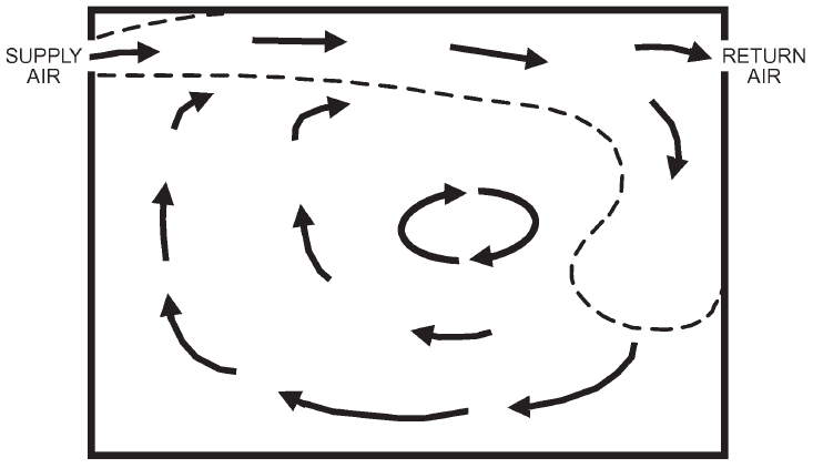
Figure 1 shows two distinct flow patterns. Displacement flow has minimal mixing of the air in the room; Entrainment flow with very poor mixing in the room has been called short circuiting flow because the air leaves the room without mixing with the room air. Although, there is little evidence that a properly designed, installed and operated air distribution system suffers from short circuited flow.

(b) Displacement Flow (b) Entrainment Flow Figure 1: Air flow patterns within a space (section view), ASHRAE Handbook – Fundamentals [5]
For displacement flow airflow pattern, the return air from the room can have a higher temperature than the general room temperature, particularly with a low level supply designed to encourage high level stratification. This temperature differential is related to the sensible heat gain and supply air mass flow. Table 4 quantifies the largest room temperature differentials for various applications.
Table 4: Typical cooling temperature differential for various applications, CIBSE Guide B [4]
Application Maximum Temperature Differential (K) High ceiling (large heat gains/low level input) 12 Low ceiling (air handling luminaires/low level input) 10 Low ceiling (downward discharge) 5 This temperature differential is useful to keep the equipment (located at low level) in air that is at a much lower temperature compared to the air temperature close to the ceiling.
Displacement flow which occurs with low level supply air will ensure the air local to the equipment has a lower temperature than the overall room air temperature. This reduces the quantity of supply air required for ventilation, which is why it is ideal for applications with high room gains.
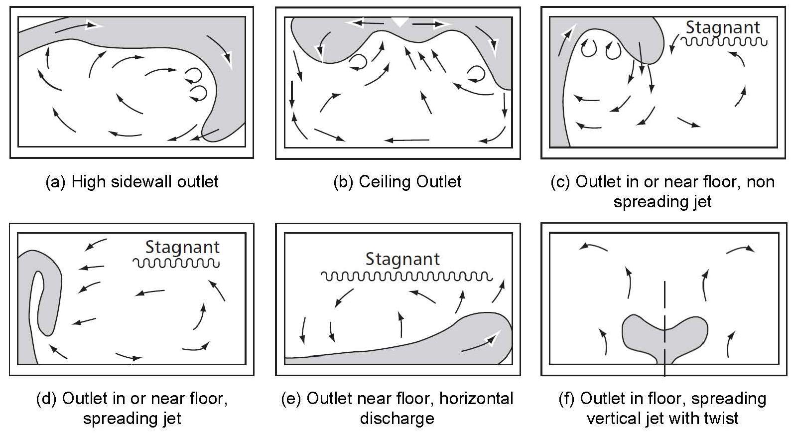
The supply air velocity needs to be coordinated with the air supply grille geometry to achieve the required spread and throw of air into the room. These parameters and the position of the grille in the room will determine the flow pattern, seen in Figure 2. If the supply grille is located at high level the air drop needs to be considered.
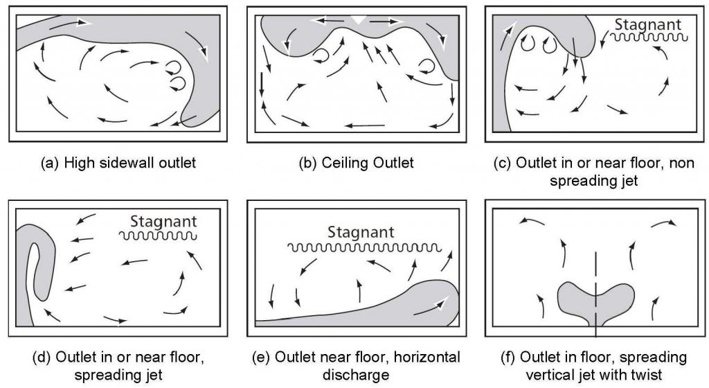
Figure 2: Predicted airflow patterns – room section, ASHRAE Handbook – Fundamentals [5]
Although the exhaust terminal has little influence on the airflow in the room, locating it where the air is the highest temperature (often above equipment with the largest heat gain) will ensure the maximum heat gain is removed from the room. This is achieved by minimising the amount of hot air mixing with the cooler areas of air in the room, reducing the overall room temperature of the air in the room. This can also help to eliminate any stagnation in the room.
2.11.3 Conclusion
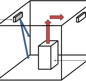
When designing an effective ventilation system for equipment rooms (an example is shown in Figure 3), the temperature difference between the supply and extract air for that room needs to be maximised. Since the temperature of the supply air is usually fixed, ensuring that the air temperature of the extract air is as high as possible will minimise the ventilation requirements of the room.
The supply air grille location & geometry and supply air velocity needs to be carefully coordinated to try to produce displacement airflow across the room. This will reduce the risk of stagnation of the air in areas of the room, which would lead to high temperatures occurring. Short circuited flow in the room needs to be avoided because this will severely reduce the temperature of the air being extracted and increase the temperature of the air to cool the equipment.
The air extract grille needs to be placed in an area of the room where the air is at its highest temperature. This is generally close to the equipment which produces the highest heat gains or coordinated with the room airflow, if it has been designed to carry the air with a hotter temperature away from the equipment.
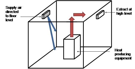
Figure 3: Drawing demonstrating optimised mechanical ventilation system
3 Sump Rooms
Sump Rooms include the rooms where the sump pump control panel is located. These rooms may be classified as Critical Sumps but not necessarily.
3.1 Contract Requirements
The high level Crossrail Programme Functional Requirements state the following:
- A drainage system shall be provided within the Central Operating Section for tunnels, cross-passages and intermediate shafts. The system shall be sized to accommodate water from a complete fire main section in the event of a burst. The system shall also handle the amount of water likely to be used in the fire fighting.
- The sumps shall be fitted with pumps. The requirement for gas detection and monitoring equipment shall be considered during the development stage. Sumps and pump rooms shall be adequately vented to prevent the build-up of gasses and oxygen depletion.
- There shall be no back flow from the sewer system to the drainage system.
- To prevent inflow of debris to station and portal sumps, static bar screens shall be required with appropriate bar spacing as per the applicable standards.
- All sumps at low points shall be provided based on the RAM analysis derived from the Central RAM Requirements [Ref. R.18].
- Forced ventilation equipment shall be provided at each low point sump where personnel entry is required.
- The pumping stations shall be fitted with hydrocarbon sensors to control the risk of accidental discharge of petroleum based hydrocarbons.
- Drainage systems shall be controlled and monitored from the RCC (or LU equivalent for systems which drain into LU facilities).
3.2 LU Standards
LU Standard 1-068 Issue A3 [6] states:
3.5.6 Drainage pump rooms and toilets shall be provided with mechanical extract ventilation discharging to atmosphere shall be independent of other systems and have auto changeover dampers and duplicate fans.
3.3 Minimum Performance Criteria
Minimum Requirements
The sump pump room containing the Electrical Distribution Board and Control Panel shall be ventilated.
Ventilation shall ensure that the room temperature does not exceed 40oC.
Extract shall be achieved using an appropriate mechanical system.
Make-up air or forced supply air shall be drawn from wherever is most appropriate but not the train running tunnels.
The ventilation shall be operated by temperature and hydrocarbon sensors in the room and by a manual switch outside the door of the room.
The extract system could be combined with air extract from other spaces. If this is the case then the system control may not be via manual switching.
In the event of a fire in the station the sump pump is to remain available to run and the ventilation system disabled.
The mechanical extract system shall have N+1 redundancy in the fans.
Mechanical cooling is unnecessary.
The extract shall not be recirculated to other accommodation spaces.
Commentary
The ventilation system to these rooms is not a Critical system.
4 Mess Room
A Mess Room is a staff rest room with domestic catering facilities and may include a small two-ring electric cooking hob.
4.1 Contract Requirements
LU Guidance note G-074 [3] states the following:
5.1.6 All mess or canteen areas with gas or electric cookers will have cooker hoods with exhaust air extraction to atmosphere and have washable grease filters. Where it is not possible to terminate to atmosphere, individual cooker hoods may have carbon filters and recirculated exhaust air.
4.2 Minimum Performance Criteria
Minimum Requirements
Design either:
A ducted extract system directly to outside where the mess room has an external wall to allow this to happen without an extended ductwork system. The extract will be via a domestic type cooker hood with particulate filtration.
or
Where the mess room does not have an external wall, then a recirculation exhaust air hood with particulate and carbon filters shall be specified. In addition an air extract from the room shall be provided, from a suitable ducted extract system, with the extract point being located, at a distance from the hood and hob to not influence the air flow through the hood. The ventilation rate shall be designed to suit the occupancy and the heat gains to the space. The general air extract may be ducted from a suitable common extract system. The extract from the mess room should not be a part of any air recirculation system. The extract air may be used for heat recovery.
Air ventilation rate shall, as a minimum, meet the building regulation requirements for domestic kitchens. They shall be calculated taking account of the heat gains, fresh air requirements, heat loss of the room and air supply temperatures to provide comfortable conditions for the majority of the year.
The means by which the design temperatures are achieved should allow the set point to be varied.
Commentary
This is not a Critical Room and so does not need to be maintained operational in an emergency condition.
5 Tea Rooms and Tea Points
These rooms are for staff use. They will be small rooms primarily for making drinks. They may include domestic catering facilities such as a fridge and kettle. They would not be used for cooking and would not be used as rest rooms where seated occupancy would be for more than a few minutes.
5.1 Minimum Performance Criteria
Minimum Requirements
The air ventilation rate shall, as a minimum, meet the building regulation requirements for domestic kitchens. They shall be calculated taking account of the heat gains, fresh air requirements, heat loss of the room and air supply temperatures to provide comfortable conditions for the majority of the year.
Commentary
Mechanical cooling is not required.
This is not a Critical Room and so does not need to be maintained operational in an emergency condition.
6 Toilets, Changing Facilities and Cleaners’ Rooms
6.1 Toilets
Normally these have extract air systems directly to outside so that smells do not cause a nuisance to surrounding areas of accommodation. The make-up air supply may be by transfer from surrounding spaces or mechanically supplied. They may be fully heated for comfort or just to protect the water systems from freezing.
Toilets could include any combination of the following:
- Public toilets
- Staff toilets
- Single WC
- Multiple WCs
- Female toilets
- Male toilets
- Mixed use toilets
6.2 Changing Facilities
Normally these have extract air systems directly to outside so that smells do not cause a nuisance to surrounding areas of accommodation. The make-up air supply may be by transfer from surrounding spaces or mechanically supplied. They may be fully heated for comfort or just to protect the water systems from freezing.
Changing facilities could include any combination of the following:
- Male changing
- Female changing
- Locker rooms
- Baby changing
- Showers and washing facilities
6.3 Cleaners’ Rooms
Normally these have extract air systems directly to outside so that smells do not cause a nuisance to surrounding areas of accommodation. Where chemicals are stored and managed for ordinary daily cleaning duties then the extract air system would prevent a build-up of chemicals in the air should a spillage or other unusual event occur. The make-up air supply may be by transfer from surrounding spaces or mechanically supplied. They may be fully heated to protect the water systems from freezing.
Cleaners’ Rooms could include:
- Station platform cleaners’ room
- Cleaning equipment room
- Cleaners cupboard
6.4 Regulations
Building Regulations Approved Document F [7] is the basis for setting minimum criteria for sanitary accommodation including WC, urinals and showers.
LU Standard 1-068 Issue A3 [6] states:
3.5.6 Drainage pump rooms and toilets shall be provided with mechanical extract ventilation discharging to atmosphere shall be independent of other systems and have auto changeover dampers and duplicate fans.
6.5 Minimum Performance Criteria
Minimum Requirements
Where the facility is significant, meaning either there are number of toilets, changing or cleaners’ rooms connected to the same extract air system then:
- Duty/ standby fans should be provided.
- Toilets, changing and cleaners rooms may be combined onto the same extract air system.
- The air shall not be recirculated back into the building.
- The extract air may be used for heat recovery.
- Make-up air should be provided by air transfer from surrounding spaces. If this is completely impractical a mechanical supply air system may be designed.
- The minimum amount of heating shall be designed to each space. In room heaters shall be simple, electric, robust and vandal proof.
Where the facility is a single space or perhaps two WCs, then:
- A single fan would be sufficient.
- The air shall not be recirculated back into the building.
- The extract air may be used for heat recovery.
- Make-up air should be provided by air transfer from surrounding spaces. If this is completely impractical a mechanical supply air system may be designed.
- The minimum amount of heating shall be designed to each space. In room heaters shall be simple, electric, robust and vandal proof.
Mechanical cooling is unnecessary.
Commentary
These are not Critical Rooms and so do not need to be maintained operational in an emergency condition.
7 Bin Stores
A bin store could have in it a container for rubbish. This would normally have a lid and wheels. The content of rubbish would be varied and include organic (food waste, dead animals collected from the railway) and inorganic (paper, metals, plastics).
Bin stores should be sited where they are easily accessed. Often they will be at ground floor level on an outside wall with doors allowing the bins to be moved directly to outside. Sometimes the bin stores are below ground.
7.1 Minimum Performance Criteria
Minimum Requirements
A bin store should be sited so that it can be naturally ventilated to outside without causing a nuisance to adjacent accommodation.
Where this is not possible a ducted mechanical extract air system is required.
The system shall be dedicated to the bin store or combined with other bin stores but should not be connected to other rooms.
The air shall be exhausted directly to outside and not be recirculated.
Make up air shall be by transfer from surrounding spaces.
Duty/ standby fans are not necessary.
Mechanical cooling is unnecessary.
Commentary
These are not Critical Rooms and so do not need to be maintained operational in an emergency condition.
8 Transformer Rooms
Transformers should be located in an outside space so that they can be naturally ventilated.
Transformers may have to be located within the Station, Shaft or Portal and mechanical cooling would be required.
Transformers are deemed Critical Equipment and so the fans and any associated cooling equipment should be resilient to failure and have redundancy of N+1.
Should fans and cooling serving a transformer room fail then the temperature in the room would rise and reach a temperature where the heat gain is equal to the heat loss due to conduction through the room’s bounding surfaces. The transformers will have a ‘cut out’ temperature typically of 550C. At this temperature the transformer would switch off and need to be manually reset.
8.1 Minimum Performance Criteria
Minimum Requirements
Dissipate the heat produced by the transformers to satisfy the temperature requirements considering in order of preference, from most preferred to least preferred, the following methods:
- Natural ventilation.
- Mechanical extract air ventilation with supply air from the adjacent space.
- Mechanical extract and supply air ventilation.
- Mechanical extract air ventilation with supply air mechanically cooled.
- Recirculation air mechanically cooled.
Mechanical systems shall have redundancy of N+1.
Mechanical air systems do not need to be dedicated to serving the transformer rooms.
The transformer rooms should continue to be operational in the event of a confirmed fire alarm. Where the room is mechanically ventilated or cooled then it is not expected that these systems operate irrespective of where the fire is. Passive heat dissipation may be sufficient in most circumstances through the year and in emergency modes.
The extract air may be used for heat recovery.
9 Low Voltage, LV and High Voltage, HV Switch Rooms, SR
Switch Rooms contain electrical switch panels. Heat losses from such panels are minimal and unpredictable.
Typically the heat loss to an HVSR panel might be 0.1% of the connected load. So for a connected load of 1MW a heat loss of 1.0 kW might be realised.
Where power factor correction and other equipment is located with the electrical switch panels each piece of equipment needs to be assessed for its heat loss.
These panels, and their content, are robust and can tolerate extremes of temperature. The switch gear could be sensitive to condensation formation which would occur at certain times of the year. When low ambient temperatures occur the panels will tend to these temperatures. As the ambient conditions change and should the moisture content increase then the panel temperature will lag the air temperature and, being cooler, condensation could occur. Panels should be provided with anti-condensation heaters.
9.1 Minimum Performance Criteria
Minimum Requirements
Dissipate the heat gain of the switch rooms to satisfy the temperature requirements considering in order of preference, from most preferred to least preferred, the following methods:
- Natural ventilation.
- Mechanical extract air ventilation with supply air from the adjacent space.
- Mechanical extract and supply air ventilation.
- Mechanical extract air ventilation with supply air mechanically cooled.
- Recirculation air mechanically cooled.
Mechanical systems shall have redundancy of N+1.
Mechanical air systems do not need to be dedicated to serving the switch rooms.
The switch rooms should continue to be operational in the event of a confirmed fire alarm in the Station, Shaft or Portal. Where the room is mechanically ventilated or cooled then it is not expected that these systems operate irrespective of where the fire is. Passive heat dissipation may be sufficient in most circumstances through the year and in emergency modes.
The extract air may be used for heat recovery.
Ensure that condensation formation within the components of the electrical panels does not occur.
10 Uninterruptable Power Supply, UPS, Equipment Rooms
UPS units are designed to provide rectification of their design electrical capacity over a wide range of temperature, from 0oC to 40oC. The environment in which they operate affects their working life but their ability to meet their stated electrical capacity is not affected.
UPS equipment is designed to switch off the inverter upon an over temperature condition occurring within the unit.
The ‘Standby Operation’ load figures are applicable for the design of cooling.
10.1 Minimum Performance Criteria
Minimum Requirements
Each room shall be controlled to the widest possible temperature range.
The temperature range shall be agreed with the responsible designer of the equipment for each room.
No room air humidity control is required.
Where temperature control is to be achieved using chilled water the cooling unit shall be located outside the room served and the air circulated to and from the room in the most appropriate way.
The UPS rooms should continue to be operational in the event of a confirmed fire alarm. Where the room is mechanically ventilated or cooled then it is not expected that these systems operate irrespective of where the fire is. Passive heat dissipation may be sufficient in most circumstances through the year and in emergency modes.
Adequate space for plant maintenance and replacement shall be provided, without affecting the operation of the Station.
Mechanical systems shall have redundancy of N+1.
Commentary
Where mechanical cooling using Variable Refrigerant Flow or chilled water is used then some dehumidification will be obtained.
11 Battery Rooms, BAT
There is a separate technical paper covering the environmental control of Battery Rooms.
12 Emergency Switch Room, ESR
Use the criteria and apply them as for UPS and BAT rooms.
13 Communication Equipment Rooms, CER
The actual heat loads are likely to be small compared with the installed connected load for the equipment. This equipment will be primarily of computer servers with communications to outside the room to field devices.
CCTV cameras, for instance, have PoE (Power over Ethernet) where they are within 90m from the CER. This power would originate in the CER cabinets but only appear as heat at the cameras.
Also the quiescent power loading of the PA system is approximately 3% of its “broadcasting” loading which is the peak load stated for the equipment design data. PA/VA broadcasts are intermittent so actual power loading and heat rejection is much less. A ‘broadcast’ profile should be produced by the designer. Until such time a constant load is assumed.
The maximum permitted room temp is 40oC. This equates to a communications cabinet internal temperature of 60oC.
13.1 Minimum Performance Criteria
Minimum Requirements
Each room shall be controlled to the widest possible temperature range.
The temperature range shall be agreed with the responsible designer of the equipment for each room.
No room air humidity control is required.
Where temperature control is to be achieved using chilled water the cooling unit shall be located outside the room served and the air circulated to and from the room in the most appropriate way.
The CERs should continue to be operational in the event of a confirmed fire alarm. Where the room is mechanically ventilated or cooled then it is not expected that these systems operate irrespective of where the fire is. Passive heat dissipation may be sufficient in most circumstances through the year and in emergency modes.
Adequate space for plant maintenance and replacement shall be provided, without affecting the operation of the Station.
Mechanical systems shall have redundancy of N+1.
Commentary
Where mechanical cooling using Variable Refrigerant Flow or chilled water is used then some dehumidification will be obtained.
14 Station Computer Room, SCR
Use and apply as for the CERs.
15 Station Operations Room, SOR
These are normally occupied rooms.
In a Critical Occurrence (loss of A&B electrical supplies) staff will direct the evacuation from this room. Certain functions, those not supported by UPS, will cease to operate. The staff will have the ability to open doors to the SOR should the temperature rise.
15.1 Minimum Performance Criteria
Minimum Requirements
Each room shall be controlled to the widest possible temperature range.
The temperature range shall be agreed with the responsible designer of the equipment for each room.
No room air humidity control is required.
The room shall be permanently occupied. The environmental design shall be based on the comfort of these occupants.
Where temperature control is to be achieved using chilled water the cooling unit should be located outside the room served and the air circulated to and from the room in the most appropriate way. Otherwise cooling units should be wall mounted. Ceiling mounted units shall not be located above desks and computer equipment.
The SOR should continue to be operational in the event of a confirmed fire alarm. Where the room is mechanically ventilated or cooled then it is not expected that these systems operate irrespective of where the fire is. Passive heat dissipation may be sufficient in most circumstances through the year and in emergency modes.
Adequate space for plant maintenance and replacement shall be provided, without affecting the operation of the Station.
Mechanical systems shall have redundancy of N+1.
Commentary
Where mechanical cooling using Variable Refrigerant Flow or chilled water is used then some dehumidification will be obtained.
16 Signalling Equipment Room, SER
The railway will stop operating in a Critical Occurrence. The signal system will be required to set, monitor and record the final condition of the signals.
These rooms are very similar to the CERs with heat gains being much less than the cabinet power input.
16.1 Minimum Performance Criteria
Minimum Requirements
Each room shall be controlled to the widest possible temperature range.
The temperature range shall be agreed with the responsible designer of the equipment for each room.
No room air humidity control is required.
Where temperature control is to be achieved using chilled water or refrigerant based systems the cooling unit shall be located outside the room served and the air circulated to and from the room in the most appropriate way.
The SERs should continue to be operational in the event of a confirmed fire alarm. Where the room is mechanically ventilated or cooled then it is not expected that these systems operate irrespective of where the fire is. Passive heat dissipation may be sufficient in most circumstances through the year and in emergency modes.
Adequate space for plant maintenance and replacement shall be provided, without affecting the operation of the Station.
Mechanical systems shall have redundancy of N+1.
Commentary
Where mechanical cooling using Variable Refrigerant Flow or chilled water is used then some dehumidification will be obtained.
17 Signalling Electrical Supply Room, SES-R
The rooms will contain Communications cabinets, UPS inverter and supporting batteries.
17.2 Minimum Performance Criteria
Minimum Requirements
Each room shall be controlled to the widest possible temperature range.
The temperature range shall be agreed with the responsible designer of the equipment for each room.
No room air humidity control is required.
Where temperature control is to be achieved using chilled water or refrigerant based systems the cooling unit shall be located outside the room served and the air circulated to and from the room in the most appropriate way.
Each room shall be ventilated to external atmosphere in accordance with EN 50272 using the gassing rate of batteries as confirmed by the framework supplier.
A suitable make up air supply shall be designed so that a negative pressure is normally experienced in the room.
The SES-Rs should continue to be operational in the event of a confirmed fire alarm. Where the room is mechanically ventilated or cooled then it is not expected that these systems operate irrespective of where the fire is. Passive heat dissipation may be sufficient in most circumstances through the year and in emergency modes.
Adequate space for plant maintenance and replacement shall be provided, without affecting the operation of the Station.
Mechanical systems shall have redundancy of N+1.
Commentary
Where mechanical cooling using Variable Refrigerant Flow or chilled water is used then some dehumidification will be obtained.
18 Lift Equipment Room, LER
An UPS will power the lift to a floor of evacuation and for the use of the fire brigade.
Some LER have a dedicated UPS in the room. Where the UPS and associated batteries are in the room the worst case heat gain to the room would be on charging the batteries and would be in the order of 470 W. The discharge time and time for the lift to move would be less than 60s.
Most LER do not have a dedicated UPS in the room but are fed from one of the central UPS systems. A total equipment heat gain of approximately 50 W could be expected.
The LER’s also contain the electrical and control cabinet for the lift.
Natural passive dissipation of heat should be practical for all these rooms. A transfer air path to an adjacent space may suffice. At worst mechanical extract with a make-up air path suffice. It is not expected that mechanical cooling be required.
18.1 Minimum Performance Criteria
Minimum Requirements
The temperature in the room shall be allowed to fluctuate to a minimum and maximum temperature such that these do not affect the normal operational use of the lifts.
The temperature range shall be agreed with the responsible designer of the equipment for each room.
No room air humidity control is required.
Ventilation shall ensure that the design room temperature is not exceeded.
Ventilation to LERs, without a UPS, should be achieved using natural or mechanical ventilation only.
Should a proposal be made for temperature control using chilled water or refrigerant based systems the cooling unit shall be located outside the room served and the air circulated to and from the room in the most appropriate way.
The LERs should continue to be operational in the event of a confirmed fire alarm. Where the room is mechanically ventilated or cooled then it is not expected that these systems operate irrespective of where the fire is. Passive heat dissipation may be sufficient in most circumstances through the year and in emergency modes.
Adequate space for plant maintenance and replacement shall be provided, without affecting the operation of the Station.
Commentary
Cooling should be achieved using ventilation.
Where mechanical cooling using Variable Refrigerant Flow or chilled water is used then some dehumidification will be obtained.
19 Lift Shafts
The equipment in the shaft will include the lift car, drive motor and integral variable speed drive. The electrical input shall vary with the load of the car and frequency of use.
The shaft will be formed of fire rated walls, soffit and pit and landing and car doors. Some air leakage from and to the shaft will occur even with all the doors closed. The air leakage will be greater for doors in the open position.
BSEN 81 no longer suggests the provision of a vent path for air to escape to outside but alerts the designer to consider the need for ventilation. A ducted path to outside for smoke relief, in the event of fire, or to overcome pressures due to lift car movement is not a requirement governed by standards.
Passive dissipation of heat via conduction through the shaft fabric and air leakage paths should be achieved. Fire fighting shafts which are mechanically pressurised will also have open ducted paths out of the shaft. These will promote air movement for heat dissipation.
Typically for the lifts in stations, which are of low speed and not extensive in distance travelled, the heat gains to the shaft would typically be 800 W averaged over 20 hours and 0 W over 4 hours.
19.1 Minimum Performance Criteria
Minimum Requirements
The temperature in the shaft shall be allowed to fluctuate to a minimum and maximum temperature such that these do not either impact the comfort of the people using the lift car or affect the normal operational use of the lift.
The temperature range shall be agreed with the responsible designer of the equipment for each shaft.
No air humidity control is required.
Temperature control should be achieved using passive means only through conductive losses of the shaft construction and ventilation via the door leakage and regular opening and closing.
Commentary
Mechanical cooling and mechanical ventilation are not required.
If the shafts’ passive heat loss to and gains from the adjacent areas are not sufficient to maintain the agreed temperatures then additional passive vent openings should be designed.
20 Escalators Equipment Room, EER
These rooms will contain Communications racks, Variable Speed Drives and motor control equipment.
There are two principle types of EER:
- A room, with a fire compartment enclosure, which is separate from the escalator truss and barrel.
- A room which is integral with the escalator truss and barrel. These rooms may be called a machine room or upper machine room/ chamber, UMC, for instance.
Both room types will have heat loads that will need to be dissipated.
Type 2 will effectively be open to the public area via the escalator treads. Air can flow either way through the treads. So could smoke. A smoke extract system is required to mitigate for smoke migration from the EER to the public area.
20.1 Minimum Performance Criteria
Minimum Requirements
The temperature in the room shall be allowed to fluctuate to a minimum and maximum temperature such that these do not affect the normal operational use of the escalators.
The temperature range shall be agreed with the responsible designer of the equipment for each room.
No room air humidity control is required.
Where temperature control is to be achieved using chilled water or refrigerant based systems the cooling unit shall be located outside the room served and the air circulated to and from the room in the most appropriate way.
Adequate space for plant maintenance and replacement shall be provided, without affecting the operation of the Station.
A smoke extract system shall be designed for EERs directly connected to the escalator truss and barrel.
Commentary
Where mechanical cooling using Variable Refrigerant Flow or chilled water is used then some dehumidification will be obtained.
21 Corridors
These spaces are used for circulation of staff, staff access, equipment removal and replacement and escape of public and staff.
They are relatively inert spaces containing very little combustible material or powered equipment.
21.1 Minimum Performance Criteria
Minimum Requirements
No specific ventilation is required.
No humidity control is required.
No temperature control is required.
22 Risers
These spaces are used for the vertical distribution of mechanical, electrical, public health and fire engineering services.
They are relatively inert spaces containing very little combustible material or powered equipment.
22.1 Minimum Performance Criteria
Minimum Requirements
No specific ventilation is required.
No humidity control is required.
No temperature control is required.
23 Mechanical Equipment Rooms
These rooms contain fans, air handling units, pumps and other mechanical equipment. They may also contain motor control centres, MCCs, variable speed drives and other electrical equipment associated with the operation of the motor driven equipment.
They will be irregularly occupied.
23.1 Minimum Performance Criteria
Minimum Requirements
Dissipate the heat gain of the rooms to satisfy the temperature requirements considering in order of preference, from most preferred to least preferred, the following methods:
- Natural ventilation.
- Mechanical extract air ventilation with supply air from the adjacent space.
- Mechanical extract and supply air ventilation.
- Mechanical extract air ventilation with supply air mechanically cooled.
- Recirculation air mechanically cooled.
Mechanical air systems do not need to be dedicated to serving the rooms.
The extract air may be used for heat recovery.
Ensure that condensation formation within the components of the electrical panels does not occur.
No humidity control is required.
No temperature control is required.
24 Machine Control Centre, MCC
These rooms contain the electronic control equipment associated with the Tunnel Ventilation Fans.
They will be irregularly occupied.
24.1 Minimum Performance Criteria
Minimum Requirements
Dissipate the heat produced by the electronic control equipment to satisfy the temperature requirements considering in order of preference, from most preferred to least preferred, the following methods:
- Natural ventilation.
- Mechanical extract air ventilation with supply air from the adjacent space.
- Mechanical extract and supply air ventilation.
- Mechanical extract air ventilation with supply air mechanically cooled.
- Recirculation air mechanically cooled.
Mechanical systems shall have redundancy of N+1.
Mechanical air systems do not need to be dedicated to serving these rooms.
The MCCs should continue to be operational in the event of a confirmed fire alarm. Where the room is mechanically ventilated or cooled then it is not expected that these systems operate irrespective of where the fire is. Passive heat dissipation may be sufficient in most circumstances through the year and in emergency modes.
The extract air may be used for heat recovery.
Ensure that condensation formation within the components of the electrical panels does not occur.
No humidity control is required.
25 Fan Control Room, FCR
These rooms contain the variable speed drives, VSD, and other electrical equipment associated with the operation of the Tunnel Ventilation Fans.
They will be irregularly occupied.
It is likely that the VSD’s will have a high heat loss density and so will require mechanical cooling.
25.1 Minimum Performance Criteria
Minimum Requirements
Dissipate the heat produced by the VSD’s to satisfy the temperature requirements considering in order of preference, from most preferred to least preferred, the following methods:
- Natural ventilation.
- Mechanical extract air ventilation with supply air from the adjacent space.
- Mechanical extract and supply air ventilation.
- Mechanical extract air ventilation with supply air mechanically cooled.
- Recirculation air mechanically cooled.
Mechanical systems shall have redundancy of N+1.
Mechanical air systems do not need to be dedicated to serving these rooms.
The FCRs should continue to be operational in the event of a confirmed fire alarm. Where the room is mechanically ventilated or cooled then it is not expected that these systems operate irrespective of where the fire is. Passive heat dissipation may be sufficient in most circumstances through the year and in emergency modes.
The VSD’s will react quickly to a fan enable signal. Ensure that the cooling system reacts similarly to dissipate the heat generated.
The extract air may be used for heat recovery.
Ensure that condensation formation within the components of the electrical panels does not occur.
No humidity control is required.
26 Tunnel Ventilation Fan Room
These rooms contain the fans to ventilate the running tunnels. The fans are ducted from and to the fans and the motors are within the air stream.
Generally these spaces are not ventilated. There will inevitably be some leakage through the ducted components which will provide a minimal amount of air movement through these fan spaces.
They will be irregularly occupied.
26.1 Minimum Performance Criteria
Minimum Requirements
Dissipate the heat gain of the rooms to satisfy the temperature requirements considering in order of preference, from most preferred to least preferred, the following methods:
- Natural ventilation.
- Mechanical extract air ventilation with supply air from the adjacent space.
- Mechanical extract and supply air ventilation.
Passive heat dissipation may be sufficient.
Mechanical air systems do not need to be dedicated to serving the rooms.
The extract air may be used for heat recovery.
No humidity control is required.
No temperature control is required.
27 Acoustics
27.1 Design Criteria
27.1.1 Ambient Room Noise Level Criteria
Ambient room noise level criteria have been selected based on the use of the rooms.
The acoustic criterion, for each room type, will be included as part of the Mechanical Design Criteria.
The criteria for public areas excludes noise due to train movements, PA/VA and people.
The Control of Noise at Work Regulations 2005 [8] places a duty on employers to avoid excessively high noise levels in spaces where employees will be working.
The regulations define various action levels based on a daily or weekly personal noise exposure or peak sound pressure levels as defined below:
4 — (1) The lower exposure action values are—
(a) a daily or weekly personal noise exposure of 80 dB (A-weighted); and
(b) a peak sound pressure of 135 dB (C-weighted).
(2) The upper exposure action values are—
(a) a daily or weekly personal noise exposure of 85 dB (A-weighted); and
(b) a peak sound pressure of 137 dB (C-weighted).
(3) The exposure limit values are—
(a) a daily or weekly personal noise exposure of 87 dB (A-weighted); and
(b) a peak sound pressure of 140 dB (C-weighted).
(4) Where the exposure of an employee to noise varies markedly from day to day, an employer may use weekly personal noise exposure in place of daily personal noise exposure for the purpose of compliance with these Regulations.
(5) In applying the exposure limit values in paragraph (3), but not in applying the lower and upper exposure action values in paragraphs (1) and (2), account shall be taken of the protection given to the employee by any personal hearing protectors provided by the employer in accordance with regulation 7(2).
It goes on to state in Section 7 that hearing protection zones are designated where:
7— (3) If in any area of the workplace under the control of the employer an employee is likely to be exposed to noise at or above an upper exposure action value for any reason the employer shall ensure that—
(a) the area is designated a Hearing Protection Zone;
(b) the area is demarcated and identified by means of the sign specified for the purpose of indicating that ear protection must be worn in paragraph 3.3 of Part II of Schedule 1 to the Health and Safety (Safety Signs and Signals) Regulations 1996(a); and
(c) access to the area is restricted where this is practicable and the risk from exposure justifies it, and shall ensure so far as is reasonably practicable that no employee enters that area unless that employee is wearing personal hearing protectors.
Where employees are expected to work in areas where their daily or weekly exposure levels exceed 80 dB(A), these employees should be provided with hearing protection.
On the basis of section 7— (3), any area where an employee is likely to be exposed to noise at or above an upper action value, these areas must be designated as Hearing Protection Zones.
Therefore, where any noise level exceeds 85 dB(A) or 137 dB LCpeak the space should be designated a Hearing Protection Zone, and wearing of ear defenders is mandatory. This is because the employee is likely to be exposed to noise at or above an upper exposure action value.
The wearing of hearing protection in designated zones is mandatory regardless of the time spent within that zone.
It is the responsibility of the employer to provide hearing protection in line with Section 7:
7.—(1) Without prejudice to the provisions of regulation 6, an employer who carries out work which is likely to expose any employees to noise at or above a lower exposure action value shall make personal hearing protectors available upon request to any employee who is so exposed.
(2) Without prejudice to the provisions of regulation 6, if an employer is unable by other means to reduce the levels of noise to which an employee is likely to be exposed to below an upper exposure action value, he shall provide personal hearing protectors to any employee who is so exposed.
(4) Any personal hearing protectors made available or provided under paragraphs (1) or (2) of this regulation shall be selected by the employer—
(a) so as to eliminate the risk to hearing or to reduce the risk to as low a level as is reasonably practicable; and
(b) after consultation with the employees concerned or their representatives.
27.2 Room to Room Transmission
The following section presents appropriate sound insulation requirements of partitions between adjacent sensitive spaces in order to maintain appropriate internal noise levels in each space.
The issues shall be considered with regard to adjacency matrices, room sensitivities and activity noise, and the use of a simpler speech privacy method.
Speech privacy is included within BREEAM 2011 [10] and the now superseded version of BS8233:1999 [9].
The latest version of BS8233:2014 [9] uses a more complex matrix to determine sound reduction, which is used in the latest BREEAM assessments.
The privacy approach is also used within the British Airports Authority Heathrow Airport Limited Design Performance Standard: Acoustics for Buildings to determine the acoustic performance of internal building elements. This has been used as the basis of the privacy table, with extension for total privacy and the use of either dB(A) or NR for the background component.
The privacy index is obtained by summing the level difference DnT,w between adjacent sensitive spaces and the ambient noise level in the receiving room, and can be determined using the following equation:
P = DnT,w + B
In general, the ambient noise in the receiving room is made up of the combination of noise intrusion from external sources such as road/rail noise, and any internal mechanical noise sources, such as the ventilation systems.
When considering speech privacy, it is important that the ambient noise level assumed in determining the privacy index is achieved as low ambient noise levels are often the cause of poor speech privacy. However, it should be noted that the ambient noise level should not be too high otherwise this leads to unpleasant and tiring spaces and complaints will be likely from the occupants.
Once determined, the privacy index is compared to a set of privacy criteria ranging from audible and intelligible to confidential. See Table 5.
Where amplified speech use is likely to occur, the requirements for privacy rating must be increased by 5 dB.
Table 5: Privacy Ratings
Privacy Rating Privacy Index Privacy Index Description of Privacy (DnT,w + NR) (DnT,w + dB(A)) Total Privacy 85 90 Raised speech virtually inaudible Highly Confidential 80 85 Normal speech virtually inaudible.
Raised speech not intelligible
Excellent 75 80 Normal speech audible but not intelligible Good 70 75 Normal speech audible but not intrusive Poor 65 70 Speech is clearly audible and intelligible None <60 <65 No speech privacy In order to achieve the ambient noise level criteria specified, partitions between adjacent sensitive spaces shall be specified to achieve an ‘Excellent’ privacy rating. Where amplified speech is likely, Highly Confidential privacy should be sought.
The sound insulation of any partition will be limited by sound transmission through weaknesses in the partition (e.g. doors, glazing, openings). The sound reduction index of a door is limited by air gaps surrounding the door. Given that DDA requirements, practicality and maintenance can influence the requirement for door seals, it is proposed that only perimeter door seals would be required (no threshold seals). This would only be to noise sensitive spaces. The door-set should achieve 30 dB Rw where seals are required and 25 dB Rw without seals.
Consideration should be given to full door seals where practical and where plant noise break-out would result in ambient noise levels in adjacent spaces exceeding the criteria specified.
Penetrations and fire stopping also cause weaknesses in partitions and floors. Windposts and movement joints also undermine the performance of partitions, and suitable detailing is required to ensure these do not undermine the partition performance.
Sound reduction between adjacent spaces should be determined based on the criteria proposed in Table 5.
The criterion specified shall be used to determine the required sound reduction dependent upon the ambient noise criteria.
A privacy rating of ‘Excellent’ shall be used, whereby the privacy index required is DnT,w + NR > 75, or DnT,w + dB(A) > 80. These are equivalent measures.
It should be noted that the DnT,w is not dependent upon the reverberation time of the receiving room, and so the absorption in each space does not affect the partition specification.
27.3 Reverberation
The following section presents appropriate criteria for the control of reverberation in sensitive spaces.
These design criteria are based on experience of absorption requirements in these types of spaces to control mechanical services noise and allow sufficient intelligibility of PA/VA systems.
Guidance in BREEAM[10] , BS8233:1999[9] and Building Bulletin 93[11], together with typical requirements for achieving suitable speech intelligibility have been used in determining required reverberation times. The criteria in BS8233:1999[9] are considered onerous, and these have now been removed from the 2014 edition. The BAA HAL standard is also more onerous than BB93, and often states that the PA/VA requirements take precedence.
However, as the requirements of BREEAM [10 do not apply, the less onerous but still appropriate requirements of BB93 have been selected to apply. Even though BB93 sets criteria suitable for schools, it is often seen as a pragmatic approach for determining criteria when other sources are not available, or considered unduly onerous.
Reverberation times are quoted in terms of the mid-frequency reverberation time, Tmf, which is the average of all third octave bands between 400 Hz and 2500 Hz, or octave bands between 500 Hz and 2000 Hz.
To achieve speech transmission index STI of 0.5 for emergency PA/VA systems, a reverberation time of less than 1.2 seconds is normally required (except in large spaces). Other reverberation times have been selected based on reasonable speech intelligibility for the type of space, or to control overall reverberant noise build-up.
Table 6: Reverberation Time Criteria
Room Use Maximum Reverberation Time [Tmf (s)] Concourse/Platform To PA/VA requirements Escalator To PA/VA requirements Locker Room / Changing Rooms ≤1.2 (Suitable STI) Meeting Room ≤0.8 (From BB93) Offices ≤1.0 (From BB93) Staff Accommodation ≤1.0 (From BB93) Toilets ≤1.5 (From BB93) 28 Typical Chilled Water Valve Arrangement
Where a chilled water system is designed the following minimum requirements are applicable:
28.1 Minimum Performance Criteria
Minimum Requirements
A chilled water system shall be for variable volume flow.
A typical valve train arrangement applicable to all terminal units, including fan coil units (FCUs), air handling units (AHUs) and close control units (CCU) is shown in Figure 4. This shall be adapted and applied as necessary to suit the particular applications.
The inclusion of strainers at each terminal unit is to be discouraged and generally should be unnecessary.

Abbreviation Definition PICV Pressure Independent Control Valve TP Test Point NC Normally Closed AV Air Vent FCU / CCU Fan Coil Unit / Close Control Unit OP Orifice Plate DC Drain Cock Figure 4: Typical Chilled Water Valve Arrangement
29 Heat Loss in an Enclosure
The following section contains an investigation into the temperature within an enclosure containing working plant components.
29.1 Background
It is important to evaluate the expected inside temperature within an enclosure. Plant within the enclosure may not be rated for use at extreme temperatures, any increase or decrease in the inside temperature could cause undue stress on components and possibly cause them to fail. A specification for mechanical systems may state that control devices are capable of operating within temperatures of 0oC to 40oC. From this information the investigation should focus on keeping the temperature of any enclosure beneath 40oC in order not to damage any components or put the system in danger of failure.
29.2 Discussion
In order to calculate the inside temperature a number of other factors need to be taken into account. Assuming the maximum temperature in extreme conditions outside of the enclosure is 30oC a relationship can be found between the inside temperature within an enclosure, manufactured out of 9.5mm Durasteel, with an internal heat load produced by a control panel.
From the graph of Figure 5, in order to keep the inside temperature of a Durasteel enclosure below 400C, assuming a constant outside temperature of 300C, a surface area of at least 25 m2 must be obtained.

Figure 5: Inside Temperature with a varying surface area for extreme high outside temperature (300C)
One option to reduce the required surface area of the enclosure would be to reduce the temperature outside the enclosure. The outside temperature would be the temperature of a plant room; this room should be ventilated or cooled allowing constant temperature monitoring to take place. If the temperature is kept at around room temperature (200C) then the surface area of the enclosure may be reduced. This is shown in the graph of Figure 6.
Figure 6: Inside temperature with a varying surface area for room outside temperature (200C)
Now with a controlled outside temperature the surface area required for the enclosure is almost halved at 13m2. Finally, the heat load is investigated. For the above results a constant heat load of 1320W was used. If this can be reduced for the majority of operation then again, the surface area required for the enclosure to remain below 400C would be reduced. The results are shown in the graph of Figure 7.
Figure 7: Surface area with a varying heat load given 200C outside temperature and 380C inside temperature
Figure 8 shows the relationship between the heat load and the surface area given the enclosure is in a controlled room kept at 200C and keeping the inside temperature of the enclosure below 400C. It shows that any reduction in heat load will allow the further reduction of the enclosure surface area.
29.3 Conclusion
For a plant enclosure containing a control panel exerting a constant heat load of 1320W the surface area must be of a certain value in order to keep the inside temperature of the enclosure below 40oC. Presuming the temperature outside the enclosure is an extreme high temperature the surface area of the enclosure required would be 25m2 in order to avoid any undue stress on the control panel and avoid failure. The continued investigation showed the surface area of the enclosure could be reduced by almost half if the outside temperature was brought down to room temperature. Further investigation showed that a lower constant heat load would further bring down the surface area required to ensure the enclosure does not breach the 400C temperature limit.
30 Chiller Electrical Feed
The following section sets out a risk assessment of the electric supply to chillers with respect to the different failure modes
The diagrams below show two different arrangements for supplying power to the duty and standby chillers. Figure 8 shows the arrangement that has been installed where there are chillers across Crossrail. Figure 9 shows an alternative arrangement eliminating the need for an ATS or DB.
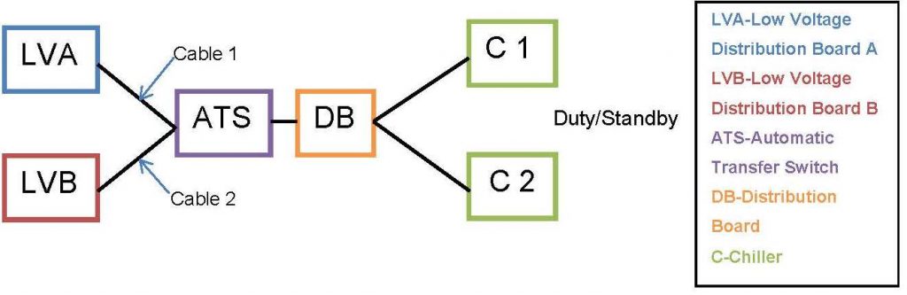
Figure 8: Electrical feed via ATS
Table 7: Failure modes with the ATS arrangement
Failed Component Chiller 1 Chiller 2 Cable 1 and/or LVA Cable 2 and/or LVB ATS DB Chiller 1 N/A No Cooling Cooling Cooling No Cooling No Cooling Chiller 2 No Cooling N/A Cooling Cooling No Cooling No Cooling Cable 1 and/or LVA Cooling Cooling N/A No Cooling No Cooling No Cooling Cable 2 and/or LVA Cooling Cooling No Cooling N/A No Cooling No Cooling ATS No Cooling No Cooling No Cooling No Cooling N/A No Cooling DB No Cooling No Cooling No Cooling No Cooling No Cooling N/A 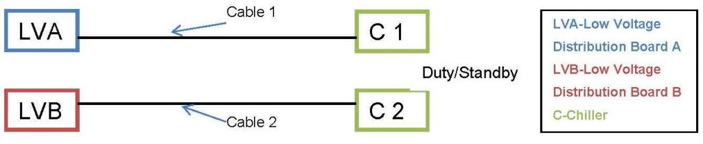 Figure 9: Direct electrical feed
Table 2: showing whether cooling will occur in the direct arrangement (diagram B)
Table 8: Failure modes with the direct arrangement
Failed Component Chiller 1 Chiller 2 Cable 1 Cable 2 Chiller 1 N/A No Cooling Cooling No Cooling Chiller 2 No Cooling N/A No Cooling Cooling Cable 1 Cooling No Cooling N/A No Cooling Cable 2 No Cooling Cooling No Cooling N/A If two components were to fail it can be seen from Table 7 that there are only 5 paths in which cooling can still occur, compared to 22 paths in which there will be no cooling. In comparison Table 8 shows there are 4 paths in which cooling can occur compared to 8 in which there will be no cooling. Therefore for electrical feed via ATS, cooling will occur 4/15 times compared to 5/15 for the direct feed. Additionally, the feed via ATS uses more parts, incurring higher costs and the need for more maintenance. If the operation arises these two arrangements should be risk assessed depending on the resilience of the components used in the system. As the direct feed uses the same components as the feed via ATS and still ensures a higher chance of cooling when two components fail, it can be assessed that the direct route would be the appropriate choice.
31 References
[1] Transport for London’s London Underground Rule Book 10 ‘Station Access’ (Issue 5, April 2014) [2] London Underground Standard – EME-ST-01-018-A2 – Mechanical Services Design [3] LUL guidance document G-074 This supports LUL Standard 1-068-A3 Mechanical Building Services, Utility Provision and Energy Management in London Underground, April 2011 [4] CIBSE Guide B: Heating Ventilating, Air Conditioning and Refrigeration, [5] 2009 ASHRAE Handbook – Fundamentals [6] LU Standard 1-068 A3 Mechanical Building Services, Utility Provision and Energy Management in London Underground, May 2011 [7] Building Regulations Approved Document F, 2006 [8] Control of Noise at Work Regulations 2005 [9] BS 8233:1999 and 2014 Guidance on sound insulation and noise reduction for buildings [10] BREEAM (Building Research Establishment Environmental Assessment Method), 2011 [11] Building Bulletin 93 -
Authors

Matthew David BSc CEng MIMechE MCIBSE - Crossrail Ltd
Matthew David is a mechanical engineer with the Chief Engineers Group. He is responsible for the assurance of the design, installation, commissioning and handover of the mechanical systems for the stations, shafts and portals. He has been with Crossrail since March 2013. He has spent the previous 31 years designing buildings, of many types, around the world.

Steven Sheridan CEng - Crossrail Ltd
Steven is a Chartered Engineer with over 20 years’ experience as a technical specialist engaged in acoustics, noise & vibration both in industry and consultancy. He has held team leadership roles over the last 10 years both internationally and in the UK in connection with the railway industry and environment & sustainability and was an Expert advisor to the European Commission on acoustics R&D. Steven has been with the Crossrail project in the CRL Technical Directorate since2010, overseeing operational and construction noise & vibration.
Specialties: Acoustics, noise & vibration, railway N&V rolling stock and infrastructure, construction site N&V, underground railway tunnel ventilation noise, fixed plant and building services noise control, environmental assessment (EIA/ES), planning & noise, railway R&D, transportation, sustainability, BREEAM, EfW, wind energy, architectural and building services.

Stephen Turley MEng CEng MIMechE MCIBSE - Crossrail Ltd
Stephen Turley is a Lead Mechanical Engineer working between the Chief Engineers Group and the Crossrail Delivery Teams. He supports the assurance and delivery of the design, installation, commissioning and handover of mechanical systems at Bond Street Station. He has worked at Crossrail since August 2014. He has spent the previous 15 years working as a Mechanical Engineer designing and delivering systems within the Building Services and Rail environment.

Robin Underwood - Crossrail Ltd
Mechanical Engineer
Joseph Kanu - Crossrail Ltd
Mechanical Engineer
Joshua Milton - Crossrail Ltd
Mechanical Engineer
Annabella Conmee
Undergraduate