Response of Buildings Supported on Shallow Footings to Tunnelling Induced Ground Movements: A Case Study of Selected Buildings at Bond Street Station.
Document
type: Technical Paper
Author:
Juliet Abbah, Deborah Lazarus MA(Cantab) CEng FIStructE FICE FRSA, Taher Jiwanji, ICE Publishing
Publication
Date: 31/08/2016
-
Read the full document
Introduction
The Crossrail works at Bond Street station comprised the construction of below ground station box structures and the connecting station platform tunnels. The layout of the station is shown on plan in Figure 1. Construction of the two 10 metre diameter platform tunnels approximately 240 metres in length (along with associated cross-passages and adits) was undertaken beneath London’s Mayfair district. The platform tunnels were formed by enlarging sections of the Crossrail bored tunnel (6.8 metres diameter) using Sprayed Concrete Lining (SCL) techniques. The ground conditions comprised Ground underlain by Alluvium, River Terrace Deposits, London Clay, Lambeth Group, with Thanet Sand and Chalk at depth. The tunnels were constructed at depths between 20m and 24m below ground level, entirely within London Clay stratum.
The tunnels were excavated beneath a number of historical buildings, the majority of which are supported on shallow footings.
Movement recorded during the works was caused by construction activities including:
- Installation of tubes a manchettes used for the compensation grouting;
- box and shaft excavation;
- twin bored tunnel excavation; and
- sprayed concrete lined (SCL) tunnels, including the station platform tunnel enlargement and associated connecting passages and adits.
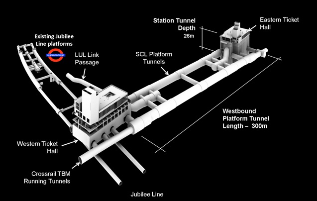
Figure 1a – Crossrail Bond Street Station Layout 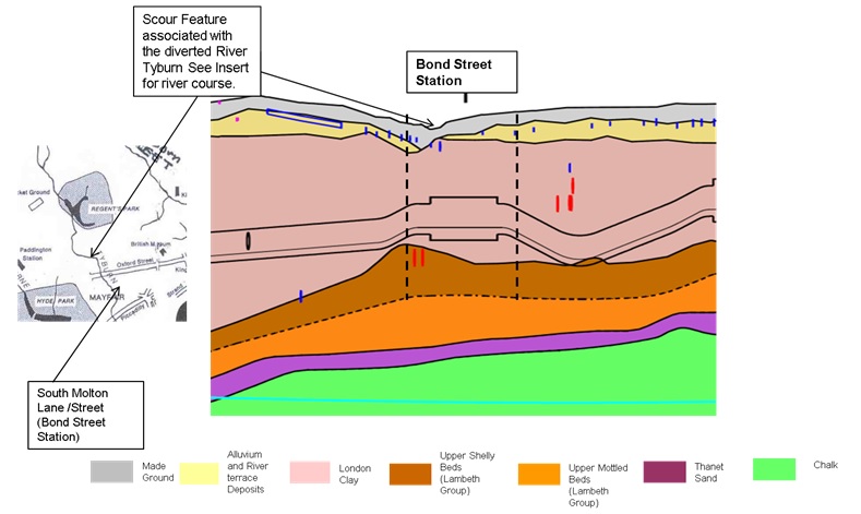
Figure 1b – Ground Conditions at Bond Street The aim of this paper is to evaluate the influence of the construction works on adjacent ground and buildings. This case study focuses on the effects of the westbound platform tunnel enlargement on selected buildings at Bond Street, particularly along New Bond Street, South Molton Street and Davies Street. These locations are marked on Figure 2. The monitoring results of ground and building deformation and damage observed in the buildings are analysed and compared to those developed using analytical and empirical methods.
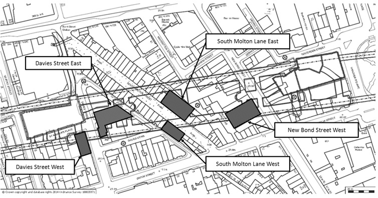
Figure 2 – Building Location Plan The westbound platform tunnel enlargement was undertaken between November 2013 and May 2014. Tunnel advance was typically 4m/day; several stops were made to undertake works associated with the construction of access passages and adits connecting the platform tunnel with other station infrastructure. The key tunnelling dates at the selected locations are shown on Table 1.
Key Construction dates for the Westbound Platform Tunnel Enlargement works Location Start Date End Date New Bond Street West 24/11/2014 02/12/2013 South Molton Street East 19/01/2014 30/01/2014 South Molton Street West 05/02/2014 10/02/2014 Davies Street East 15/02/2014 20/04/2014 Davies Street West 25/03/2014 20/04/2014 Table 1 – Key Tunnelling Dates
Damage Assessment and Mitigation
Methodology
The impact on buildings due to movements from the construction of Crossrail tunnels and associated station boxes were assessed using a combination of analytical and empirical methods. The estimates of Greenfield settlements were used to calculate building distortions and the horizontal strains (Burland et.al, 1997 and Boscardin et.al, 1989). The method used is set out in Crossrail design standards.
A predicted damage category for each asset was calculated and ranges from 0 (negligible) to 5 (Very severe) conforming to the standard system of classification developed by Burland, 1995. The categories are presented in Table 2.
Damage category Description of degree of damage Description of typical damage and likely forms of repair for typical masonry buildings. Approx. crack width (mm) Max. tensile strain % 0 Negligible Hairline cracks. <0.05 1 Very slight Fine cracks easily treated during normal redecoration. Perhaps isolated slight fracture in building. Cracks in exterior visible upon close inspection. 0.1 to 1.0 0.05 to 0.075 2 Slight Cracks easily filled. Redecoration probably required. Several slight fractures inside building. Exterior cracks visible; some repainting may be required for weather-tightness. Doors and windows may stick slightly. 1 to 5 0.075 to 0.15 3 Moderate Cracks may require cutting out and patching. Recurrent cracks can be masked by suitable linings. Tuckpointing and possible replacement of a small amount of exterior brickwork may be required. Doors and windows sticking. Utility services may be interrupted. Weather tightness often impaired. 5 to 15 or a number of cracks ≥ 3 0.15 to 0.3 4 Severe Extensive repair involving removal and replacement of walls especially over doors and windows required. Window and door frames distorted. Floor slopes noticeably. Walls lean or bulge noticeably. Some loss of bearing in beams. Utility services disrupted. 15 to 25 but also depends on number of cracks > 0.3 5 Very severe Major repair required involving partial or complete reconstruction. Beams lose bearing, walls lean badly and require shoring. Windows broken by distortion. Danger of instability. Usually > 25 but depends on number of cracks Table 2 – Building damage classification
For listed buildings, the vulnerability of special features and sensitivity of the structures were taken into account in assessing the risk of damage. Where a high damage score (3 and above) was predicted, and for significant listed buildings, visual inspections were undertaken to identify any issues of condition or structural form which might need further considerations when assessing the impact of ground movement on the building’s response.
The assessment at the design stage estimated that the construction of the Crossrail platform tunnels at Bond Street was likely to cause some level of damage to structures and services within a zone defined by the 10mm settlement contour. This, together with the constraints imposed by 3rd party asset owners and formalised in specific undertakings, necessitated the design of a robust ground movement mitigation measure, in this case compensation grouting, to reduce the risk of damage to buildings and other services.
To monitor and respond to the impacts during the works, a simple system of 4 trigger levels was implemented on site which comprised: Green, Amber, Red and Black triggers.
- The Green and Amber trigger levels are related to the values of ground surface / building displacement or distortion predicted in the impact assessment. The Amber trigger is normally set at the maximum predicted value, and the Green trigger at 80% of this value.
- The Red trigger level is intended to be set at a conservative estimate of the maximum tolerable displacement / distortion.
- A Black trigger invokes an immediate emergency response and may or may not be associated with a numeric value.
Damage to buildings / structures and utilities is generally associated with distortion, rather than displacement alone. Triggers for these assets have been related to distortion: i.e. change in gradient (slope) and deflection ratio, between surveys points at ground level (studs in ground surface and base of buildings).These are summarised in Table 3.
Trigger Values for Asset Protection
Green Amber Red Change to gradient (Slope) 1:1250 1:1000 1:800 Deflection Ratio 1:2000 Table 3 – Summary of Trigger Values
The compensation grouting was designed to keep the change in ground slope to 1:1000 and the risk of damage to “very slight” (Category 1) or lower. As such, the compensation grouting performance requirements of a change of slope of 1:1000 (calculated at facades and party walls) and deflection ratio of 1:1000 was set for works in the areas where compensation grouting had been specified.
Compensation grouting
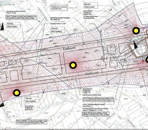
Compensation grouting, comprises the injection of a cement – bentonite grout mix in arrays above the tunnel during excavation to minimise settlement of the ground above and therefore the impact on buildings on shallow foundations. Compensation grouting was actively implemented to reduce the total and differential settlements during the platform tunnel enlargement. The grouting was carried out from five grout shafts installed at the locations shown in Figure 3a. Grout injection tubes, Tubes-a-Manchette (TAMs), were installed from these grout shafts at levels between 110m ATD and 112m ATD as shown in Figure 3b.
Compensation grouting was used to ‘hold’ and ‘slightly lift’ the structures during the platform tunnel construction (“concurrent grouting”). Grouting using the TAMs was also carried out prior to and after the occurrence of ground movement (“corrective grout jacking”) where necessary to correct for slopes or movements that occurred prior to and after the tunnelling works. No grouting was undertaken within 4.5m of the crown of the active tunnelling work as shown Figure 3c. This defined the “exclusion zone” around the tunnels.
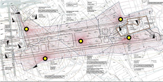
Figure 3a – Compensation Grouting extent and Grout shaft locations 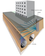
Figure 3b – Sketch showing Tubes a Manchette 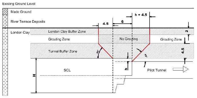
Figure 3c – Grouting Exclusion Zones Instrumentation and Monitoring
Comprehensive monitoring was installed over the site to closely monitor the impacts of the works on assets and to control construction. Asset protection monitoring comprising automated 3D geodetic prisms and manually surveyed building levelling points was installed on the external façades of the buildings whilst precise levelling monitoring points were installed at transverse and longitudinal directions along the tunnel alignment and on the buildings.
A network of water levelling cells (referred to as Hydrostatic Levelling Cells (HLCs)) was installed within the basements of the buildings to provide real-time monitoring for control of the compensation grouting works.
The real-time monitoring systems provided data every 15 minutes whilst manual monitoring was undertaken daily at both ground and building points when the tunnelling and associated mitigation works were being undertaken within pre-defined zones of influence.
Additional instruments including tilt meters, crack meters and tell-tales were installed at locations where defects were identified during pre-construction surveys so as to monitor changes in condition at specific points. Typical cross sections showing the instrumentation and monitoring scheme are provided in Figure 4.
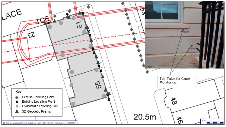
Figure 4 – Typical Instrumentation Scheme Building Response
Displacement – time plots showing the development of displacements at the ground and building facades are shown in Figure 5. The vertical displacements shown on the graphs are based on the data obtained from the levelling points installed on the ground (PLPs) and building (BREs). Additional checks have been made with the automated systems to check for consistency in the data. The data show the results to be broadly similar although the movements obtained from the prisms are slightly higher than those obtained from the HLCs.
The plots show the ground (PLPs) and buildings (BREs) movements to be broadly similar in most of the areas under consideration except to the west of Davies Street, where it would appear that the buildings have settled more than the adjacent ground. Typical time history plots showing the movements for selected points installed on the building façade are presented in Figure 6.
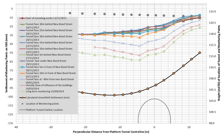
Figure 5a – Ground Settlement measured along New Bond Street West 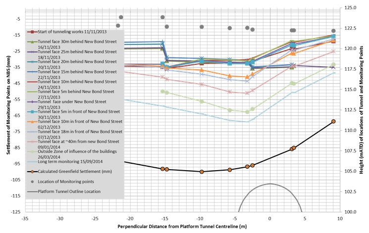
Figure 5b – Building Movement measured along New Bond Street West 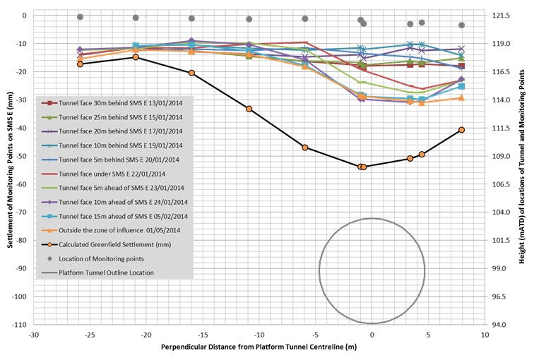
Figure 5c – Ground Movement measured along South Molton Street East 
Figure 5d – Building Movement measured along South Molton Street East 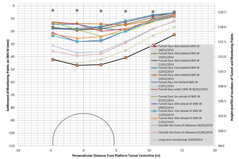
Figure 5e – Building Movement measured along South Molton Street West 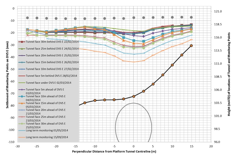
Figure 5f – Ground Movement measured along Davies Street West 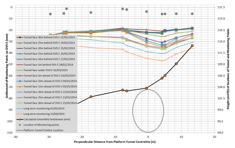
Figure 5g – Building Movement measured along Davies Street West 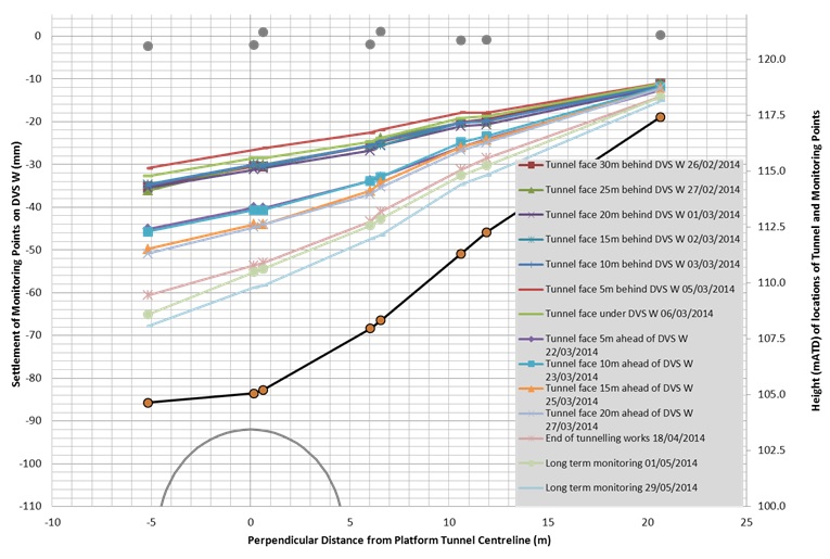
Figure 5h – Building Movement measured along Davies Street East 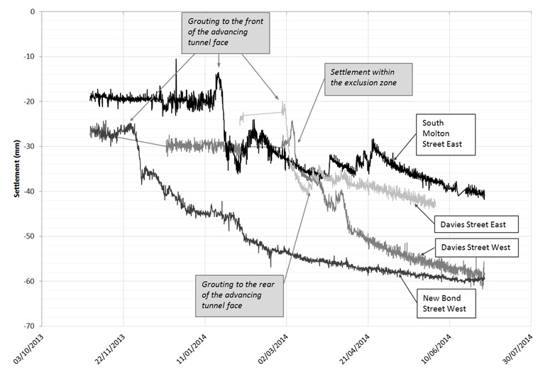
Figure 6 – Settlement-time plot for selected building points above tunnel. The results show uplift (heave) during concurrent compensation grouting prior to tunnel excavation followed by the settlement induced during the tunnelling. An increased settlement was observed at the surface when the buildings “came within” the compensation grouting exclusion zone.
The results of the measured vertical displacement are compared to the calculated green field displacement in Figure 5 (a-h). It is recognised that the magnitude and pattern of the displacement observed at Davies Street West is different from the calculated. The difference is mainly due to the simple empirical ground movement curves used in the calculation to represent the displacements due to the excavation of the western ticket hall.
In comparing the actual behaviour against the predicted behaviour, the following outcomes are noted:
- The total settlements observed are less than the calculated Greenfield settlement.
- The slopes due to the observed movement are less onerous that those calculated in the damage assessment. This is consistent with using the use of relatively conservative parameters in the assessment, which also did not consider the explicit benefit from the use of grouting.
- There was varying response to the compensation grouting with some areas responding rapidly upon grouting and in other areas little or no response observed, even though similar grout volumes were injected.
- There was increased settlement within the SCL exclusion zone with the limited response following further injections of grout to the rear of the advancing tunnels leading to several instances of slope trigger level breaches within the compensation grouting zone.
- It can also be seen that ground relaxation occurred soon after the completion of the grouting episode, thus contributing to a reduced grouting efficiency.
Figure 7 shows the development of the horizontal movement in the north- south direction for selected points located on the buildings considered in this case study. The results of the movement in the north–south direction perpendicular to the tunnel alignment are shown graphically in Figure 8. Positive values on the graph indicate movements to the north whilst negative values indicate movements to the south.
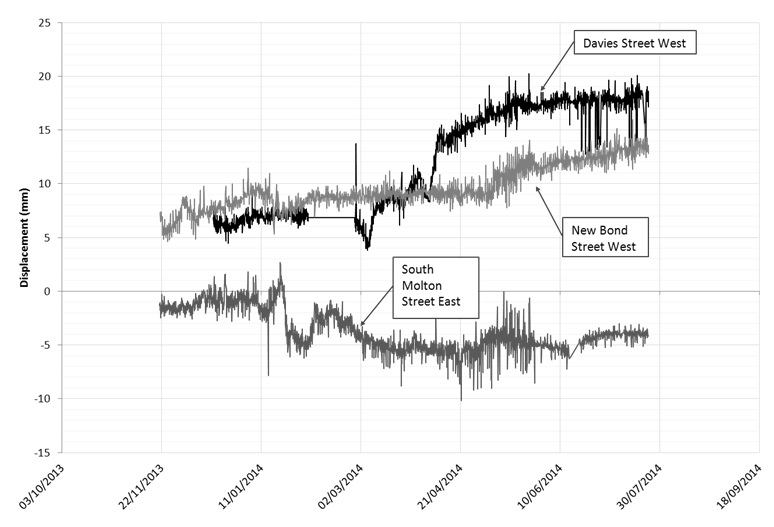
Figure 7 – Time-history plot for horizontal movement in the North – South direction The results show an increased movement to the north following the commencement of the compensation grouting. These movements were reduced following the commencement of tunnelling works. This observation was consistent in all facades being monitored, except at Davies Street west where the observed movement was mostly to the north as shown in Figure 7.
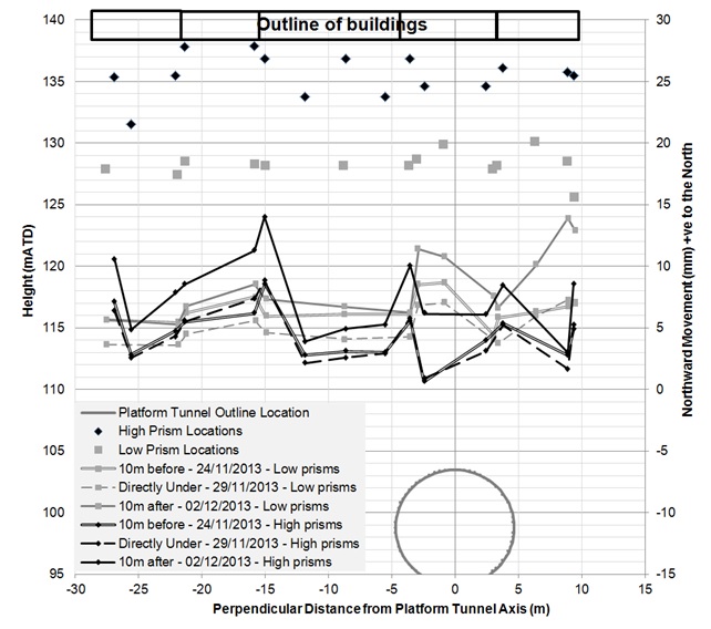
Figure 8a – North-South Horizontal Movement measured along New Bond Street West 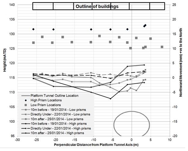
Figure 8b – North-South Horizontal Movement measured along South Molton Street East 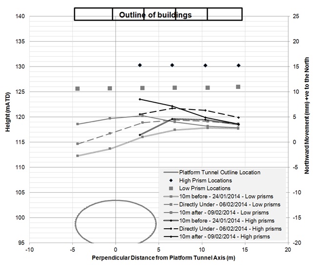
Figure 8c – North-South Horizontal Movement measured along South Molton Street West 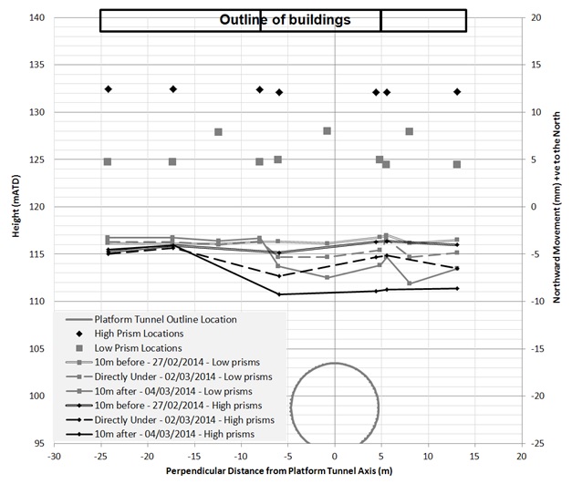
Figure 8d – North-South Horizontal Movement measured along Davies Street East 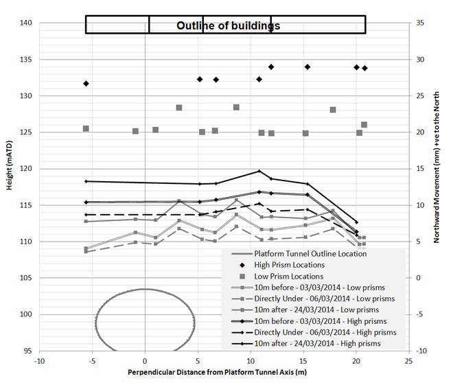
Figure 8e – North-South Horizontal Movement measured along Davies Street West Figure 9 shows the time history plot of the horizontal movement in the east-west direction during the tunnelling and associated grouting works. The results of the movement in the east–west direction perpendicular to the tunnel alignment are shown graphically in Figure 10. Positive values on the graph indicate movements to the east whilst negative values indicate movements to the west. The results show an increased movement to the east following the commencement of the compensation grouting in advance of the tunnelling works. The eastward movement was reversed by movement to the west during SCL tunnelling ending up with a net movement to the west.
The following observations were made regarding the observed horizontal movement:
- The buildings rotated away from the tunnel axis during compensation grouting works when uplift was generated.
- Conversely the buildings rotated towards the tunnel axis in response to the settlement induced during the tunnelling works. The movement continued as more vertical displacements was observed following the completion of the tunnelling works.
- Other non- platform tunnel sprayed concrete lining works were also observed to have effects on the overall distortion of the buildings. For example, the construction of a Cross Passage (CP5) to the rear of the South Molton Street buildings caused the rear of the buildings to tilt north, away from the platform tunnel.
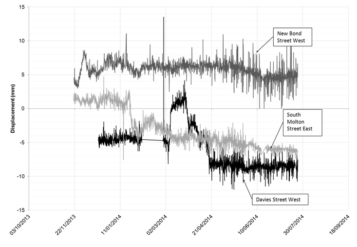
Figure 9 – Time-history plot for Horizontal Movement in East – West direction. 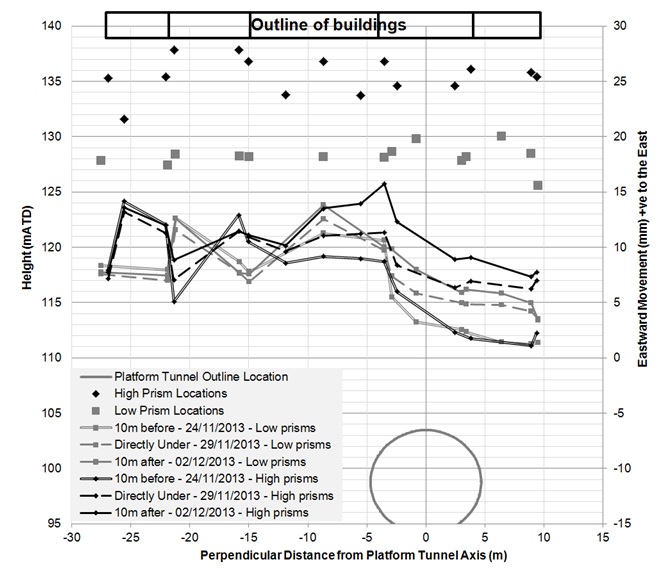
Figure 10a – East-West Horizontal Movement measured along New Bond Street East 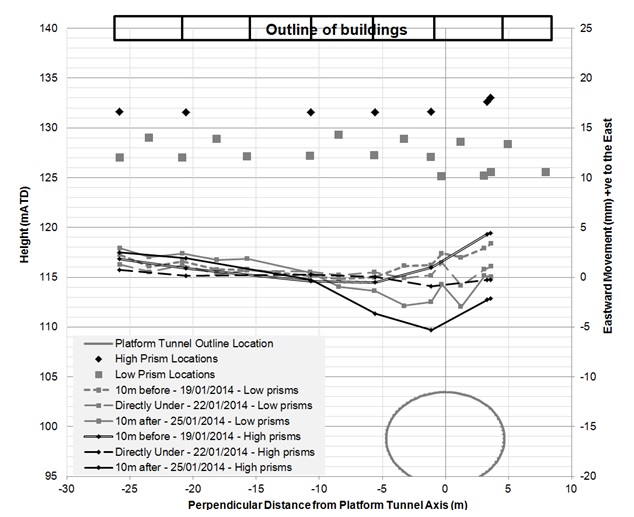
Figure 10b – East-West Horizontal Movement measured along South Molton Street East 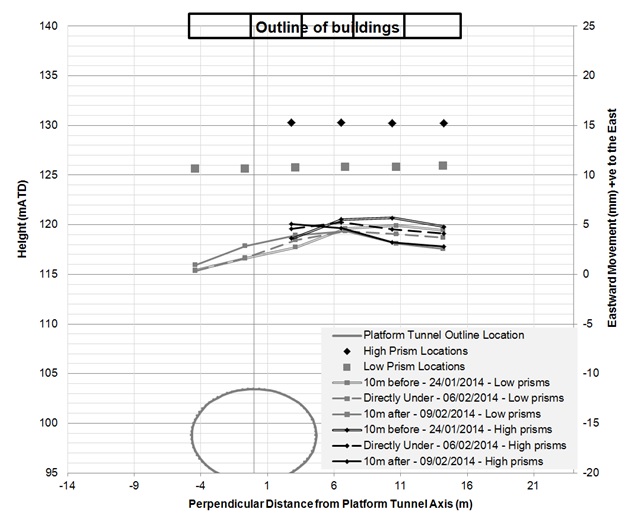
Figure 10c – East-West Horizontal Movement measured along South Molton Street West 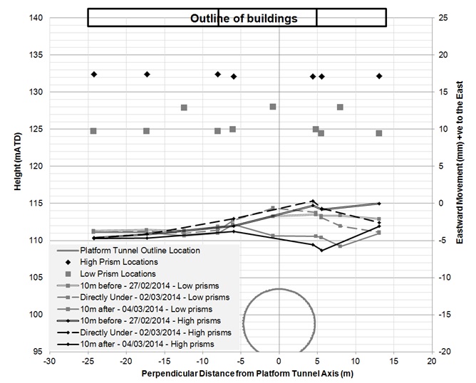
Figure 10d – East-West Horizontal Movement measured along Davies Street East 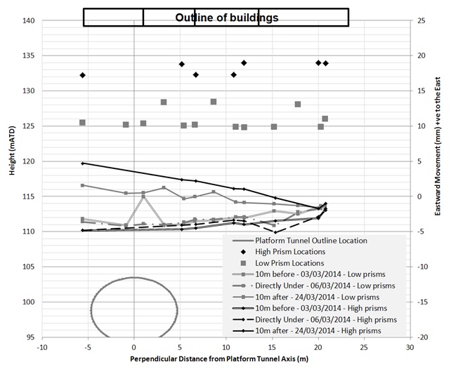
Figure 10e – East-West Horizontal Movement measured along Davies Street West Observed Building Damage
South of New Bond Street
Damage to properties was reported by occupants on New Bond Street, particularly at buildings above the tunnel alignment. This paper discusses the damage recorded at buildings to the south of New Bond Street during the construction of Crossrail westbound platform tunnel. A review of available historical information shows that the area was originally developed as part of the Corporation of London (City of London) Conduit Mead estate. Majority of the properties in the area comprise four to five storey masonry buildings, with basements and vaults constructed 18th /19th century. Reconstructions are noted to have taken place in the early 20th century at isolated locations. The later structures appear to be mainly of steel frame construction with stone and masonry cladding.
Building inspections were immediately undertaken by the site teams following the reports of damage. The inspections confirmed the development of new defects and the deterioration of existing cracks within these buildings, (when compared to the pre-construction defect surveys). The defects typically comprised sticking doors, cracks around openings (doors and windows), vertical and horizontal cracks on walls, ceilings and non-structural finishes. The most significant damage was observed in a building directly above the tunnel alignment where the screed and overlying floor finishes became damaged during the tunnelling and associated compensation grouting works as shown in Plate 1.
The majority of the cracking was noted along lines of weakness introduced during historical and recent refurbishment, for example, addition and connection of non–structural plasterboard walls to existing structural members. Inspections of the affected buildings showed no damage to the structural supports (beams and columns).
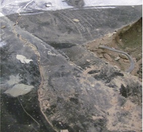
Plate 1a – Crack in floor finishes at a building at New Bond Street 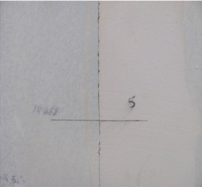
Plate 1b – Typical separation between structural wall and partition wall Plate 1 – Indicative damage observed at New Bond Street
The review of the monitoring data during the tunnelling works showed varying response to compensation grouting under the buildings with less heave induced underneath the party walls compared to the other locations within the buildings as shown in Figure 11. An increased settlement rate was noted along the centre line of the tunnel, within the compensation grouting exclusion zone. Consequently, grout injections were omitted in the areas of higher response; however, grouting was required along the tunnels to limit the settlements and the development of adverse slopes in the area.
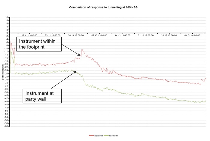
Figure 11 – Comparison of movements along New Bond Street West, located within building/ on party wall The management of the damage to this building was further complicated by ongoing refurbishment works being undertaken concurrently with the tunnelling work. The asset owner had planned to replace the existing floor finishes with brittle floor tiles which were likely to become damaged if placed whilst tunnelling/ground movement was ongoing.
It was decided to proceed with the tunnelling in order that all ground movement inducing activities in the vicinity of the building would be completed to allow the refurbishment and repair works being carried out on the building to continue.
Additional instruments, comprising precise levelling points and barcode readers, were installed on the floor and columns in order to confirm any differing response to the tunnelling works. Test grouting was then undertaken at the party wall to confirm the response to grouting. The results of the test showed further movement of the floor due to the grouting being undertaken at the party wall located approximate 12m away; little or no movement was detected on the instruments installed on the columns, thus confirming the differing response of the floor to the tunnelling and mitigation works. Tap testing undertaken at the room where the damage occurred confirmed that the floor was of varying construction, with distinct hollow sections suggesting poor bonding between finishes and slab, and more solid sections.
Further corrective grouting was not undertaken in this area even though slope trigger level breaches had been recorded, as the risk of further damage to the floor slabs remained high.
South Molton Street
The buildings along South Molton Street typically comprise terraces and are also part of the Corporation of London’s Conduit Mead Estates. The area was developed from the mid- 18th century following the below ground diversion of the River Tyburn that flowed through the area. The orientation of these buildings clearly reflects the alignment of the river as shown in Figure 1. It also appears that a number of streams/ tributaries in the area had been ‘culverted’ with time. Based on the land use history, the buildings are likely to have been founded on the made ground associated with the in-fill of the Tyburn river valley. The Pre- construction condition surveys undertaken by the design teams identified evidence of historic movements to the front façades.
These buildings appear to have undergone extensive modifications in previous and recent times to suit their use, which typically ranged from shops, cafes, residential and office accommodation. The records of these modifications were often non-existent but rear extensions, opening up to create larger spaces and blocking of disused lift shafts were common place. A high turnover of shops was noted in the areas with new owners often refurbishing and changing the layout following acquisition.
Given the known history of the area and the variable response to the mitigation works, there were concerns as to the response of these buildings. Several interventions including a reduction of the exclusion zone were implemented to improve the efficiency of the compensation grouting. Nevertheless, slope trigger level breaches continued during the tunnelling works due to ground relaxation following grouting and increased rates of settlements within the exclusion zone.
The damage that was recorded during January and February 2014, when the tunnelling was within the zone of influence of these buildings, included: separation at junctions between walls and ceilings, horizontal and vertical cracks around walls (structural and non-structural) and ceilings particularly at the rooms located at front and rear of the buildings. The crack widths were typically between 1mm and 5mm. Historical defects repaired during frequent refurbishment reopened during this period. It should be noted that new defects were reported even at locations with no trigger level breaches or direct tunnelling action. Of interest was the de-bonding and partial collapse of the lath and plaster type ceilings endemic in this area. Two incidents of partial ceiling plaster collapse were reported whilst the tunnel enlargement work was being undertaken. Another collapse was reported in July, 2014 after the completion of all tunnelling works in the area. This led to uncertainties regarding when the de-bonding of the plaster from the lath occurred and if the de-bonding was due to the ground movement or vibration associated with the tunnelling works or a combination of both, or was a result of weakening over time combined with the impact of frequent refurbishment works. Inspections following the collapse showed that in most cases alterations including the inclusion of light fittings and pipes had been made as shown in Plate 2. The collapse of the lath and plaster ceilings was a concern to the site teams as their condition were not specifically identified in the pre-construction surveys.
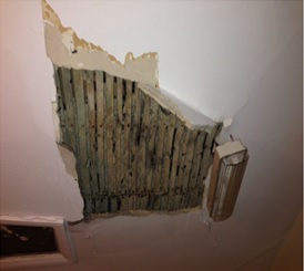
Plate 2a – Partially collapsed ceiling plaster at South Molton Street 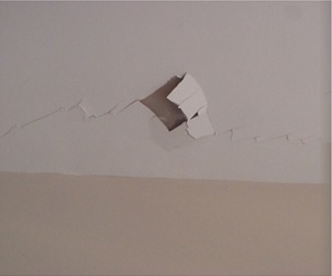
Plate 2b – Cracks observed in ceiling at South Molton Street Plate 2 – Indicative damage to ceiling plaster at South Molton Street
The effect of the distortion due to the tunnelling on selected buildings at South Molton East is shown on the annotated sketch included in Figure 12. The results suggest the rear of the buildings have moved to the north and east towards the cross passage being constructed at the rear, whereas the front façade moved to the south and east towards the platform tunnel enlargement. The effect of the horizontal movement was observed at one location where the carpet in a room pulled away from the front elevation. The observation could be symptomatic of the front wall pulling away from the internal structure. The horizontal strains in the building were not routinely calculated during the works however, the opposing movement observed at the front and rear façades could have caused additional strain, that were neither in the bending or diagonal mode considered in the damage assessment.
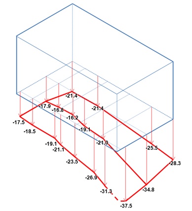
Figure 12 – Distortion of Building on South Molton Street, based on data from HLCs (displacement in mm) Davies Street
As the tunnelling works continued towards Davies Street to the west, there was continued concern regarding the potential impacts on the ’high end’ properties that form part of Grosvenor Estates in Mayfair. A review of historical information indicated that the area had previously been used as a market (including a slaughter house), stables and mixed accommodations which were subsequently demolished and redeveloped.
The buildings at Davies Street East are of different architectural styles, having been built at different era by different architects with different styles.
Figure 6 show the time settlement plot of a typical point installed in a building at Davies Street East. The high rates of settlement as the buildings entered the grouting exclusion zone and the episodes of rear injection grouting are marked on the plot. Although only limited uplift was achieved by the grouting episodes, it would appear that it was effective in preventing further settlement. However, the settlement continued following the cessation of grouting underneath the buildings.
Damage was reported at these building in March 2014, whilst tunnelling work was being undertaken in the area. The damage that was recorded in the buildings was concentrated at the party walls where the buildings have been connected. As with other locations, there was cracking at the junctions between wall and ceilings and at the junction between walls. Cracks were noted on walls and ceiling on all floors in the building as shown in the Plate 3. Pre-existing cracks, recorded at various locations, were noted to have widened, whilst plaster had de-bonded from the walls.
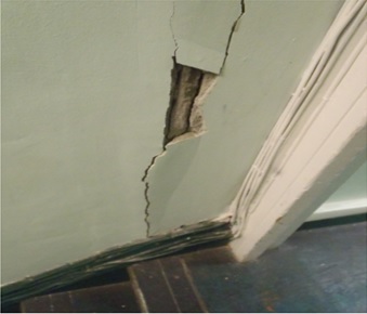
Plate 3a – De-bonding of plaster and deterioration of existing crack at Davies Street East 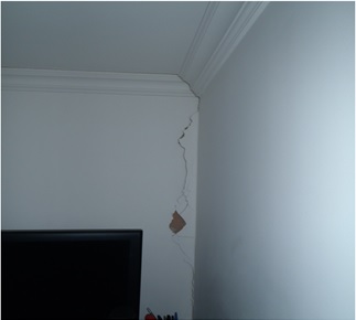
Plate 3b – Cracking observed on the party walls of adjacent buildings at Davies Street West Plate 3 – Indicative damage to walls at Davies Street Across the street (Davies Street west), the buildings are typically late Georgian style constructed between 1824 and 1827. The buildings are known to have been altered for use as offices and residential accommodation. At the time of Crossrail works, these buildings had been converted to flats. Of key concern were the cracks identified on the façade of the building prior to the start of Crossrail works.
The works in the area included the construction of the platform tunnel and an access passage (AP2A), connecting the platform tunnels with the western ticket hall box. The access passage was constructed using SCL techniques with no pilot tunnels. It was not practical to carry out concurrent grouting during construction of the access tunnel due to its short length. A programme of pre and post tunnel grouting was therefore implemented to mitigate for excavation settlement.
As with the other areas, the problems identified with rapid settlements within the grouting exclusion zone and varying grouting efficiency continued. An important difference, however, was the differing ground and building response as shown in Figure 13 for adjacent ground and building points. These show the ground to be more responsive to the mitigation (grouting) and settling less when compared to those measured on instruments installed on the buildings. The reason for the differing response remains unclear but could be due to a number of factors including: 1) the ground beneath the buildings was disturbed previously, therefore causing more settlement and; 2) the loading and connections of the building was such that grouting needed to be undertaken under larger areas of the building to achieve a suitable response to compensation grouting. A combination of the two reasons seemed to be more likely given that the PLPs responded more to the grouting work.
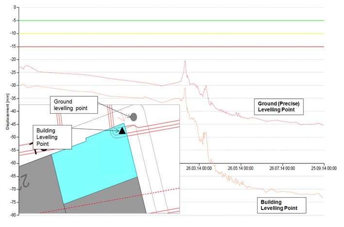
Figure 13 – Comparison of Adjacent Ground and Building Points – 61 Davies Street The differing response was noted during the works and selective grout omissions were made to keep within the limiting criteria. Slope trigger level breaches were noted along the Davies Street façade, transverse to the tunnel.
Contour plots of the horizontal movement in the north–south direction and settlement, measured along the Davies Street façade are shown in Figure 14a and Figure 14b respectively. The results show that the higher level prisms moved up to 8mm more than those installed at the lower level of the buildings, suggesting a tilt towards the tunnels. The reason for the increased horizontal movement at this location remain unclear although the location of the adjacent western ticket hall box structure and the increased settlement observed in the area due to reduced grouting efficiency may be relevant contributing factors.
Damage was recorded at several locations within these properties. These typically included separation at walls and ceilings, stair wells and decorative finishes. The cracks at the façades were also noted to have opened up during the tunnelling works. This pattern of damage was observed on all floors but appeared to be most pronounced in the basement flats closest to the tunnelling, where cracks of up to 5mm developed at party walls. The crack observed at this location is consistent with the area of high concentration of contours marked on Figure 14a.
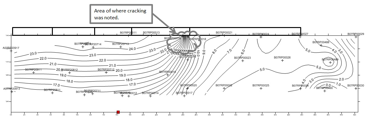
Figure 14a – Contours of horizontal movement (north –south) along Davies Street West Given the occurrence of damage and the varying response to mitigation works, further grouting was not undertaken in the area because damage had already occurred and the movements had largely stabilised. It was therefore considered best to avoid moving the ground further.
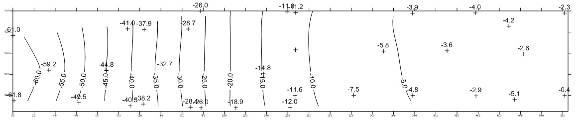
Figure 14b – Contours of vertical movement along Davies Street West Matters for Discussion
The settlement pattern observed around Bond Street appeared to be higher than normal especially when compared to movements recorded during excavation of the enlargement of the platform tunnels from bored tunnels within the London Clay stratum at the nearby Crossrail Tottenham Court Road Station works. The difference between the ground and building response at both stations is highlighted in the time settlement plot presented in Figure 15. Given that the works were undertaken by the same contractor using similar techniques, it is inferred that the differences could be due to the near surface ground conditions.
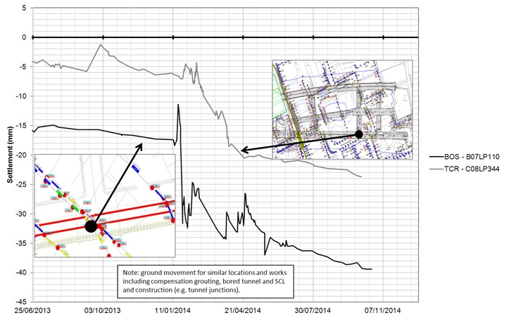
Figure 15 – Comparison of observed ground movement at Tottenham Court Road and Bond Street Station As discussed in previous sections, the River Tyburn is known to have flowed through the Bond Street station area. As with most rivers it is not clear if the last known location has always been the course of the river, as natural and man-made diversions may have occurred. A review of the topography of the area show a change of elevation (up to 4m) between Oxford Street to the north and Brook Street to the south of the platform tunnels. The layout of some of the buildings in the area, and sometimes steep slope points to smaller brooks in the area. It is obvious that the area is within the river plain of the Tyburn. It is also likely that the buildings may have been founded on reclaimed land and old river valley material. This is perceived that the consolidation of these poor materials may have contributed to the higher settlement observed in the area.
The efficiency of the compensation grouting is affected by a number of factors including fluid loss, ground conditions and grout properties. Water strikes were noted in historical ground investigation records around the levels at which the TaMs were installed and may be a contributing factor to the varied response to grouting observed. It is considered the exclusion zone limits the effectiveness of compensation grouting as a mitigation measure. It is anticipated that further review of the compensation grouting will be undertaken as a separate study.
The evaluation of the damage arising from the construction works was undertaken using traditional methods of categorizing damage by Burland et al. The method uses differential settlements and critical horizontal strains to determine damage for buildings. For listed buildings, additional damage scores were introduced to account for the sensitivity of the heritage features and sensitivity. The buildings considered in this paper had pre-existing deformation and cracking that is considered to have influenced their response to the underlying tunnelling works. From observations, the conventional accepted methods may not be accurate in predicting the damage category for these buildings as the observed damage were sometimes outside those predicted. For buildings of the age considered in this paper, it is suggested that an additional sensitivity score be included in the total damage score to account for pre-existing defects and also the rather poor construction practices that are inherent at the time of construction. Alternatively a capacity reduction factor could be applied. It is noted that some of these defects and poor construction practices only become obvious following the report of damage.
The buildings have also undergone extensive modifications through the years to bring them to modern standards and to suit the desired use of the occupants. These modifications affect the response of the buildings because the tunnel induced movements cause redistribution of horizontal and vertical loads in the structural members (e.g. support walls). The difference in stiffness caused by the introduction / connection of structural members to less stiff partition walls lead to stress concentrations and cracking where these types of modifications have been made as observed in the buildings reviewed in this case study. Buildings have also been opened up to form bigger retail spaces or art galleries. The creation of these large spaces within the masonry buildings is likely to change the pattern of the redistribution of stresses and reduce the overall bending stiffness making them prone to further damage.
The original assessment for the now interconnected buildings was performed for discrete structures. The structural assessment of the buildings was undertaken based on the Length, Height and a material parameter defined by the stiffness. The assessments generally were carried out for owners and were thus not always consistent with structural interfaces. The impact of this is perhaps something for further evaluation but lies outside the scope of this paper.
The classification of damage mainly adopted on this project is based on three broad categories namely, aesthetics, serviceability and stability. It also includes the ease with which the damage is repaired. The majority of damage was observed in the finishes and less stiff parts of the buildings. In all the buildings visited there were no concerns regarding the overall structural integrity of the buildings and the observed damage was considered to DC 2 or less. In accordance with the classification of damage, these can be classed as aesthetic damage. However, some of the damage observed, for example, the damaged floor at New Bond Street and collapsed ceiling plaster and jammed doors affected the ‘serviceability’ /use of the several parts of the buildings where these occurred. Consequently it is considered that a Burland damage category of 3 might be more appropriate when considering these buildings.
The ground movement due to compensation grouting is accompanied by horizontal movements / strains. The impacts on the observed building damage in this case study is not clear and would require further review to determine its impacts on the buildings and services being protected by compensation grouting.
Conclusion
In view of the modifications and varied response to the compensation grouting, the design is considered to be suitably robust, as the damage observed was mainly due to modifications and mode of construction associated with buildings constructed in the late 18th and 19th century. The inclusion of the effects of all the modifications and changes identified following the occurrence of damage would have led to unrealistic damage categories.
Experience and judgement remains paramount in determining the risk of damage to the buildings. The use of slopes as deflection ratio for control of the works provides a good indication of deformation, however, the routine calculation of horizontal strains, could provide additional insight on the development of new defects due to the tunnelling works.
References
Boscardin M.D and Cording J., 1989. Building response to excavation induced settlement. Journal of Geotechnical Engineering, Vol 115(1) pp 1-21
Burland J.B, Standing J.R and Jardine F.M, 2001. Building response to tunnelling: case studies from construction of the Jubilee Line Extension, London, London, CIRIA and Thomas Telford.
Burland J B (1995) Assessment of risk of damage to buildings due to tunnelling and excavation, Invited Special Lecture: 1st International Conference of Earthquake Geotechnical Engineering, IS Tokyo, 1995.
Mair R J, Taylor R N and Burland J B (1996) Prediction of ground movements and assessment of risk of building damage due to bored tunnelling (in: Geotechnical aspects of underground construction in soft ground (eds R J Mair and R N Taylor) pp. 713–718, Balkema, Rotterdam).
Mair R J, Taylor R N and Bracegirdle A (1993) Subsurface settlement profiles above tunnels in clay. Géotechnique 43 No. 2 pp. 315-320.
Sheppard F H W (ed) (1980). Survey of London: Volume 40: The Grosvenor Estates in Mayfair.
Talling Paul, (2011). Lost Rivers of London. Random House.
Taylor R N (1995) Tunnelling in soft ground in the UK (in: Underground construction in soft ground (eds K Fujita and O Kusakabe), Balkema, pp. 123-126).
The British Library (online resource), Crace Collection Maps, The Conduit Mead. The properties belonging to the City of London Surveyed in 1794.
-
Authors

