Design of Sprayed Concrete Linings in Soft Ground─ A Crossrail Perspective
Document
type: Technical Paper
Author:
Jiang Su BEng MPhil, Alun Thomas BA PhD, ICE Publishing
Publication
Date: 03/11/2014
-
Abstract
Sprayed concrete lined (SCL) tunnelling has seen rapid development over the last twenty years in the UK. The purpose of this paper is to give an update on the latest design philosophies and methodologies, and to discuss the future development trends for SCL tunnelling in soft ground.
The paper will start with brief overview of past soft ground SCL tunnel design; especially the temporary sprayed concrete lining. After that, the paper will introduce the recent and most significant shift in design philosophy; the transition from temporary sprayed concrete lining to permanent sprayed concrete lining, with its implications for construction safety, cost and environmental impact. Some recent developments in the numerical modelling techniques to facilitate the design of the permanent sprayed concrete lining will be introduced. In conclusion, the paper will discuss the possible future trends of SCL tunnel design, in particular the “composite shell” lining, with its potential benefits for construction programme, cost and environmental impact, followed by additional thoughts on possible improvements in the numerical modelling of soft ground SCL tunnels.
-
Read the full document
1 Introduction
Many people in the past have questioned the method so this paper starts with a definition of the term: An SCL tunnel is a tunnel with a Sprayed Concrete Lining. The Sprayed Concrete Lining interacts with the ground and, through the choice of excavation sequence, this interaction can be optimized to minimize the loads on the ground support. Monitoring is required for “performance verification”, to ensure that the tunnel is performing within the limits required by the design (given natural variations, for example, in advance rates and ground conditions), to determine when certain contingency measures are needed (such as temporary inverts).
The use of Sprayed Concrete Lining is an established method of soft ground tunnelling using sprayed concrete to support the excavation both temporarily and permanently. Compared with other tunnelling methods, such as using a Tunnel Boring Machine (TBM), the biggest advantage of the SCL technique is it allows tunnels and junctions to be built at varying cross sections and sizes with relative ease. As well as this, the SCL technique has low mobilisation costs, making it suitable for short lengths of tunnel construction.
2 SCL designed as temporary structures
Until recently, SCL tunnels, consisting of a layer of temporary sprayed primary lining, a layer of sheet waterproofing membrane and another layer of permanent cast secondary lining, dominated the market; mainly because of concerns over safety, watertightness and durability. For the purpose of this paper, this is called sacrificial primary SCL. The reason why the SCL was only treated as a temporary structure was due to two aspects: limitations of sprayed concrete technology and design method limitations, which will be discussed separately in the following sections.
2.1 Limitations of SCL technology
Twenty years ago, the early-age strength development was the top priority for sprayed concrete working as a ground support measure while many other properties had to be compromised, leading to SCL being treated only as a temporary structure. The main concerns at that time from the tunnelling industry about the SCL included:
- Low final strength in the long-term due to accelerator dosage (Kusterle 1997)
- Long-term durability issues due to “shadows” behind steel reinforcement (Thomas 2008)
- Poor quality control due to use of the dry-mix process and manual spraying(Austin & Robins 1995)
2.2 Limitations of design methodology
The lack of reliable design methods was another reason why SCL was perceived only as a temporary structure, especially in soft ground strata, such as London Clay. Tunnelling used to be an experience-based industry where empirical methods were widely adopted, such as using the Gaussian curve to predict the ground surface settlement profile (Peck 1969) or the Q-system (Bartonet al, 1974). However, the empirical methods for soft ground were mostly based on the assessment of previous local practices and lacked universal acceptance (ICE 2004).
Closed-form analytical methods were also developed for tunnelling design. However, most of them are not suitable for SCL tunnels as the complex soil-structure interaction caused by the multi-step SCL construction sequence could not be properly modelled. The famous closed-form Curtis-Muir Wood formula (Muir-Wood 1975, Curtis 1976), originally developed to confirm the design of segmental linings, could only be used as a check for SCL tunnels because this method assumes that the whole lining is installed immediately after the tunnel is excavated, homogeneous ground conditions and that the tunnel is perfectly circular, neither of which are generally true for SCL tunnels(ICE 2004). The convergence-confinement method (Panet and Guénot 1982), commonly used to predict the displacement field due to the SCL tunnelling, cannot predict the bending moments within the SCL linings and suffers from similar limitations to other closed-form solutions. For the beam-spring model, where the SCL lining is modelled as a series of beams connected to each other and to the ground by radial and tangential springs that simulate the ground support interaction, choosing the correct value of spring stiffness is considered to be very difficult. Besides, the loads to be applied to the lining are evaluated separately from another system, disconnecting the interaction between soil and structures (O’Rourke 1984).
The numerical modelling was not considered as a viable design tool for SCL tunnels in soft ground until 1990s, mainly due to insufficient computing capacity. The Heathrow Express Trial Tunnel, the first soft ground SCL tunnel constructed in London in 1992, was designed by using finite difference software package FLAC2D (Deane & Bassett 1995). This project represented the most advanced design at that time in the UK. The main features are:
- A conservative approach using mean and the worst case parameters for London Clay was adopted due to the absence of prior local projects
- A small strain stiffness non-linear isotropic model was used to model the pre-peak behaviour of London Clay
- A strain softening stress-strain relationship was adopted for its post-peak behaviour
- The Hypothetical Modulus of Elasticity (HME) approach was used to model the early-age sprayed concrete and the 3D effects tunnel face effect. Despite some attempts to give it a theoretical basis, the HME is effectively an empirical correction factor (Thomas 2008) –a very useful one but empirical nonetheless.
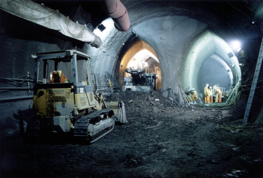
Figure 1 Temporary SCL lining of Heathrow Express crossover cavern
The success of the Heathrow Express Trial Tunnel gave the industry significant confidence in building SCL tunnels in soft ground in London. However, the Heathrow Express project still posed a much bigger challenge to the designers as it comprised three large-diameter parallel SCL tunnels, in a close proximity under the terminal building (Van der Berg et al 2003). There were also cross-passage connections between these tunnels. There were four major challenges:
- Little prior experience of additional loading to the SCL tunnels caused by compensation grouting (Linney & Essler 1994)
- Difficulty in estimating potential building damage due to SCL tunnelling induced ground movement
- Lack of knowledge on the extra loading on the adjacent SCL tunnels caused by the construction of new SCL tunnels
- Scarce data available to estimate the stress concentrations around the junctions due to the construction of the cross-passages
To ensure safety, designers put a large quantity of reinforcement in the SCL tunnels. For a 9m diameter platform tunnel, the temporary primary lining consisted of 300mm of sprayed concrete lining, reinforced by two layers of 8mm diameter mesh and full-section lattice girders, leading to a reinforcement ratio at 0.23%. This quantity of reinforcement made the spraying very difficult, leading to concerns of quality control and long-term durability of the lining.
It could be argued that the perception of SCL as only temporary structures was driven not only by insufficient development of the sprayed concrete technology, but also by the lack of efficient design methods. As an aside, it should be noted that, despite the limitations of the design, the causes for the collapse at Heathrow stemmed from failures in the construction management, particularly quality control and interpretation of monitoring data (HSE 2000).
2.3 Other issues related to temporary SCL
Until the mid 1990’s in the UK, most spraying was carried out using the dry mix method which required tunnel workers to stand very close to the tunnel face to spray the concrete, resulting in significant health and safety issues. Dry mix creates much more dust than wet mix spraying. In addition, the temporary SCL caused serious concerns of material waste, cost inefficiency and negative environment impact.
3 SCL designed as permanent structures
In order to improve the performance of SCL tunnels, constant efforts have been made by different parts of the tunnelling industry, such as material suppliers, machinery manufacturers, designers and contractors. Several advances have made the use of SCL as a permanent structure possible:
- The shift in producing SCL from the dry-mix process to a wet-mix process substantially improved the quality control and productivity (Austin & Robins 1995)
- The adoption of alkali-free accelerators enabled rapid setting, improved early and final strengths, reduced environmental impact and enhanced safety for tunnel workers (Kusterle 1997)
- The use of fibre reinforcement instead of mesh reinforcement eliminated the concern of “shadows”, shortened construction programme and saved overall cost (Thomas 2008)
- The shift from hand spraying to robotic spraying speeded up progress and produced less material waste (Franzén 1992). It also complies with increasingly strict H&S laws in the UK.
- The use of real-time surveying with total stations instead of lattice girders to ensure the correct profile of the tunnel excavation and control the lining thickness has accelerated construction and also removed a key durability concern. This has been a huge leap forward. A recent project using the total station for profile control was the Heathrow Terminal 5 project, which together with the inclined tunnel face was marketed as the “Laser Shell” method developed by Morgan Est (Jones et al. 2008)
- The improvement in the quality of sprayed concrete has enabled the mature sprayed concrete to be treated as normal cast in-situ concrete, with the same long-term strength development, low permeability (in the order of 10-12and 10-14m/s) and durability performance (Annett et al. 1997)
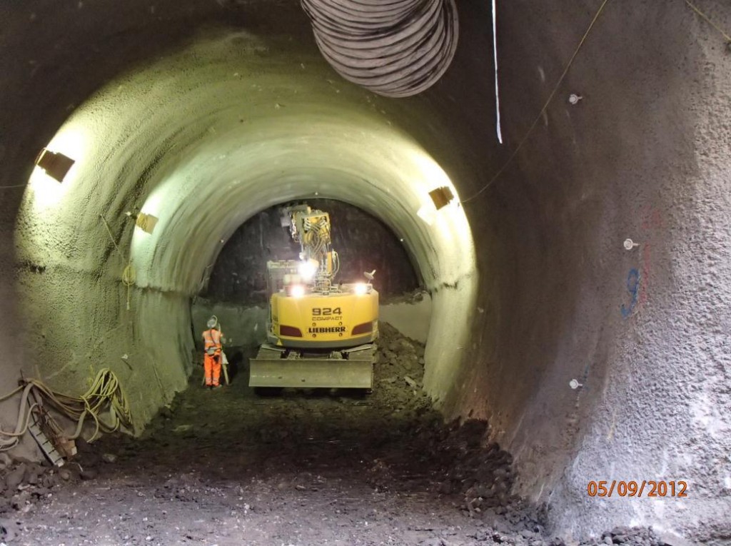
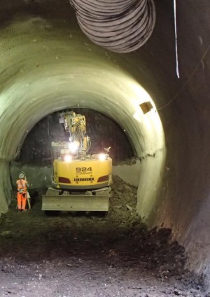
Figure 2 Permanent sprayed concrete primary lining at Limmo for Crossrail
Permanent sprayed concrete has been widely accepted in certain sectors –most notably hydropower projects –and certain countries (e.g. Norway) for many years but it has only recently gained this acceptance more widely in the world and in soft ground applications. For soft ground SCL tunnelling in the UK, for the purpose of this paper, the latest design option is called Double Shell SCL, which consists of a layer of permanent sprayed concrete primary lining, a layer of spray applied waterproofing membrane and a layer of sprayed or cast secondary lining, with no adhesive and shear bond assumed at the sprayed concrete-membrane interfaces. This was the design assumption due to the lack of evidence on the existence of adhesive and shear bond and thus no bond is assumed across the interface. Steel fibres are used as the main reinforcement, and no steel bars and meshes are used except at the tunnel junctions. Lattice girders are eliminated and the tunnel profile is controlled by the total station. This design option has been adopted on several important projects, such as A3 Hindhead and Crossrail.
3.1 Design requirements
In the latest design option, the permanent sprayed primary lining is designed to take the full short-term soil, water and any other pressures, such as surface surcharge and compensation grouting, that occur before the installation of the secondary lining. In some ground conditions there is a time-dependent ground loading as well as long term changes in water pressure. London clay is one such case. The soft ground is assumed to be impermeable within two years in an undrained short-term analysis. This assumption is consistent with the work of Wongsaroj et al (2007) who found that permeability for the clay should be in the region of 10-10 to 10-11m/s to replicate the observed behaviour in the JLE Green Park field. It also coincides with Addenbrook’s (1996) back-analysis of the running tunnels at the same field that the ground took between 10-20 years for most of the movements due to water flow to cease.
In the case of London clay, the long-term increase in soil pressure and surface surcharge are shared in proportion to the thickness between the two linings and the long-term water pressure is assumed to apply solely to the secondary lining in a drained long-term analysis. This is determined by the assumptions of cracking in the primary lining and of no adhesive and shear bond assumed across the sprayed concrete-membrane interface as mentioned above. Ground water is assumed to be able to travel from the extrados to the intrados of the primary lining through cracks and the water pressure directly applies to the sprayed waterproofing membrane and hence to the secondary lining. Depending on the time and budget, either complicated coupled consolidation analysis or simply fully permeable analysis could be carried out as the drained long-term analysis in a numerical model.
An initial layer of primary lining, normally between 25-75mm, is designed as sacrificial and disregarded in the long-term design case. This is mainly due to the quality control consideration that the quality of this layer of sprayed concrete will not be as good as the following layers. Another consideration of this sacrificial layer is to resist the chemicals in the groundwater, particularly sulphates, which would cause corrosion to the steel fibres, leading to a reduction in the effective primary lining thickness in the long-term. The thickness of the sacrificial layer is determined mainly by the type and density of chemicals in the groundwater. Arguably 75 mm is a quite conservative assumption.
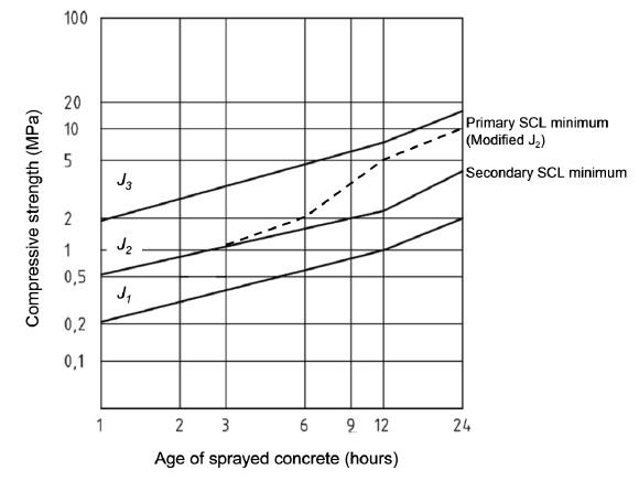
Figure 3 Early age strength development for sprayed concrete –modified J2 curve
(based on EN 14487-1:2005)A moderate strength of sprayed concrete is specified in the design and used in the construction. The lower limit of characteristic cylinder compressive strength for both linings is28N/mm2at 28 days and 32N/mm2 at 90 days respectively, and the concrete should exceed a modified J2 curve (EN 14487-1:2005) within the first 24 hours. The specification of the lower limit of compressive strength of sprayed concrete is to guarantee that the lining would fulfil its functional requirements. Although structural synthetic fibres are more economic and better in resisting corrosion (Bernard 2009), steel fibres have been chosen as the reinforcement mainly due to the better performance in resisting long-term creep in tension (Bernard 2004). As the understanding of macro-synthetic fibres develops confidence in their performance under creep is likely to increase. A 50mm fire proofing sprayed concrete layer mixed with micro-synthetic fibres is designed inside of the secondary lining to reduce the spalling of concrete in a fire situation (Shuttleworth 2001).
3.2 Design methods
Since numerical modelling is now widely used in the design of SCL tunnels, it can be considered that the way to improve the design depends on the accuracy of the constitutive models. There are three main areas where numerical modelling results could be improved: the constitutive model for the ground, the constitutive model for the sprayed concrete, and calibration of modelling approach.
Industry and academia have spent significant efforts in collecting field and laboratory test data to develop constitutive models for ground strata such as London Clay (Gasparre 2005, Jardine et al1984, 1986). It could be argued that the constitutive models for London Clay have developed to a point where doubling the time and resource input may only improve the results very slightly. Hence, it relies on the designers’ judgment to balance the accuracy of the results with the input resource to the modelling work. It should also be borne in mind that numerical modelling is just an approximation of reality, and its accuracy will be affected significantly by the selection of ground model and uncertainties of the ground (Thomas2008).
For Crossrail SCL tunnel design, A* model (Eadington & O’Brien 2011), a small strain stiffness non-linear elastic model, has been adopted. The model recognises important pre-failure behaviour of London Clay at the strains appropriate to tunnelling (Atkinson 2000, Addenbrook 1996, Addenbrook et al 1997), especially for cases where several tunnels are close together. The Tresca failure criterion with an associated plastic flow rule and the Mohr-Coulomb failure criterion with an unassociated plastic flow rule have been adopted to model the undrained and drained ground behaviour at failure and beyond respectively. The concept of a strain dependent stiffness model and failure criteria are both well-known in industry and academia and backed by significant historical data. Besides, the parameters used in these models are relatively easy to obtain, and the computing time is modest compared with that using more sophisticated models.
In contrast to the universally accepted design methods and criteria for the cast in-situ concrete, variations in SCL mix design and workmanship in different countries for different projects can affect the strength and stiffness development significantly. Tests on sprayed concrete at both early ages and long-term have been carried out by various researchers, leading to various stiffness/strength development equations (Thomas 2008). Therefore, where possible it is best to base the constitutive models on testing results from a similar, recently completed SCL project. For Crossrail SCL tunnel design, age-dependent strength curve for sprayed concrete were developed based on the modified J2 curve up to 24 hours, which was derived from the previous SCL projects, and Chang & Stille approach (Chang & Stille 1993) thereafter. The stiffness of sprayed concrete at each age was also derived from the Chang & Stille’s stress-stiffness equation. The data of sprayed concrete stiffness and strength from Heathrow T5 project and A3 Hindhead were used to check the inputs.
Eurocode 2 (BSI 2004) defines the compressive strain in normal concrete at peak stress (εc) as 0.2% and ultimate compressive strain (εcu) as 0.35%. There is currently no universally accepted stress-strain relationship for the concrete in the tension area as the tensile strength is usually very small hence not taken into account in the structural analysis. Plain concrete is a brittle material and will only exhibit a certain degree of ductility in tension when bar reinforcement or structural fibre is added. Therefore, tensile stress-strain relationships from different standards and methods are reviewed and selected for the design.
In addition, adding plastic hinges into the lining could be another way to improve efficiency in the design. Bending moment redistribution is a well-established theory in concrete structure design, fitting SCL tunnels especially well due to the structural redundancy. The combination of using an age-dependent linear elastic model and plastic hinges may substantially reduce the peak bending moment in the lining, leading to more evenly distributed bending moment and more efficient lining design at the cost of a slightly increased ground movement. This overcomes the limitations of using linear elastic elements to simulate a material which is nonlinear elasto-plastic and which creeps. The method corresponds with the experience in the field that SCL tunnels can easily redistribute stresses within themselves and the ground, provided that the ground does not become overstressed. This is a safe design method since the numerical model will predict collapse if the ground load continues to press on the area with plastic hinges, instead of redistributing.
3.3 Calibration
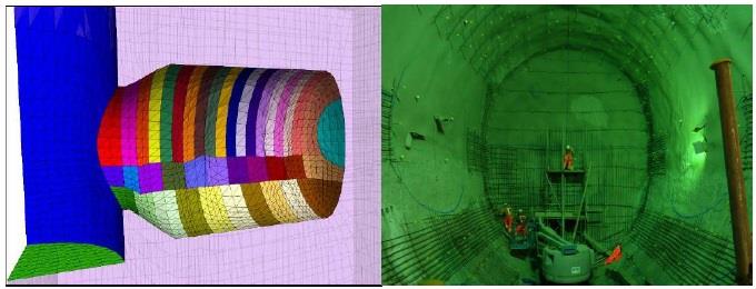
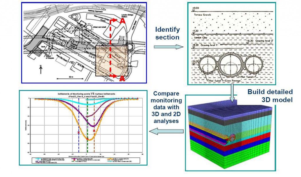
With clearly defined constitutive models for the ground and sprayed concrete, a 3D model with the correct construction sequence would be straightforward for modellers and the results should be fairly accurate. It is widely acknowledged that the 3D modelling is far better than the 2D modelling for SCL tunnels (Thomas 2003, Jones 2007) as the former can model the complicated construction sequence, and three-dimensional stress redistribution around the tunnel face explicitly. For Crossrail SCL tunnel design, 3D modelling has been extensively used for calibration works, compensation grouting and tunnel junction studies, as well as for tunnels in faulted ground and in irregular shapes. The 3D model and the construction of the Whitechapel junction enlargement are shown below in Figure 4 (a) and (b) respectively. However, it must be recognised that, compared with the 2D modelling, the 3D modelling is very time consuming and has been used only if it can be seen to improve the accuracy of results significantly.
Figure 4 3D Model (left) and the construction (right) of the Whitechapel junction enlargement using permanent SCL
In Crossrail, most SCL tunnels are still modelled by 2D analysis. To date, more than 100 2D primary and secondary lining sections have been analysed. Extensive calibration works, including the Jubilee Line Extension (JLE) London Bridge Station, Heathrow T5 and Kings Cross Station, were carried out at the beginning of design in order to verify the constitutive models and input parameters for ground and sprayed concrete. After that, a valid 2D modelling methodology was formulated and adopted for routine 2D analysis. For calibration of the numerical model, the most relevant data is tunnel convergence and lining stress directly obtained from an in-tunnel monitoring system. Tunnel designers are primarily concerned with the lining loads while ground movements are a secondary concern, when compared to the stability of the tunnel. An ideal calibration work is carried out as follows:
- Firstly, obtain field data for a completed SCL tunnel project, including ground surface and subsurface settlement curves, lining stresses and lining deformations, from a reliable source, such as a company’s own database or published papers. It should be noted there is a scarcity of such data and it is rare to find cases in the same ground
- Build a3D model for these SCL tunnels explicitly modelling the construction sequence and using the real sprayed concrete stiffness and strength
- Compare the predicted lining stress, lining deformation, ground surface and subsurface settlement curves with the field data
- It is widely acknowledged that predicting the tunnelling induced ground surface settlement trough is still a very difficult task even now (Potts &Zdravkovic2001, Addenbrook 1997). It is satisfactory if the model predicts a surface settlement profile in reasonable agreement with the measured and a volume loss similar to the calibrated data, when the primary focus is the lining design
- For SCL tunnels constructed in London Clay, the small strain stiffness non-linearity of the ground should be considered not only for predicting ground deformation, but also for assessing the strain of the ground where adjacent tunnels are to be built
- If consistency between the field data and numerical modelling prediction is unachievable for ground deformation, lining stress and convergence at the same time, a priority should be given to the set of input parameters which predict the closest lining performance to the field data
- Match the 2D modelling results with the 3D modelling results with different ground pressure relaxation percentage and using the real sprayed concrete stiffness and strength
- Ideally, the 2D relaxation percentage should enable the predicted results, including both ground deformation and lining performance, consistent with the field data
- For lining performance, it is not only necessary to check whether the predicted maximum lining stress is consistent with the field data, but also whether the lining deformation pattern is consistent with the field observation
- Different ground relaxation percentage may be developed for different construction methods, such as pilot/enlargement or top heading/bench/invert
A typical 3D/2D numerical modelling calibration procedure is shown in Figure 5.
Figure 5 Typical 3D/2D numerical modelling calibration procedure
All of the above was successfully done for the Crossrail project which represents a major achievement and an important factor in giving the project team the confidence to design and build such large and complex structures in the sensitive environment of central London.
4 Further development of SCL
Huge progress has been made over the last twenty years, during which SCL has moved from being only a temporary structure to a permanent structure without any compromise in structural capacity, watertightness, durability and safety to tunnel workers, while, at the same time, achieving shorter construction periods and savings in the materials used. The next step is to discuss whether SCL can be improved further, with even thinner linings and shorter construction periods.
4.1 Further development of SCL technology
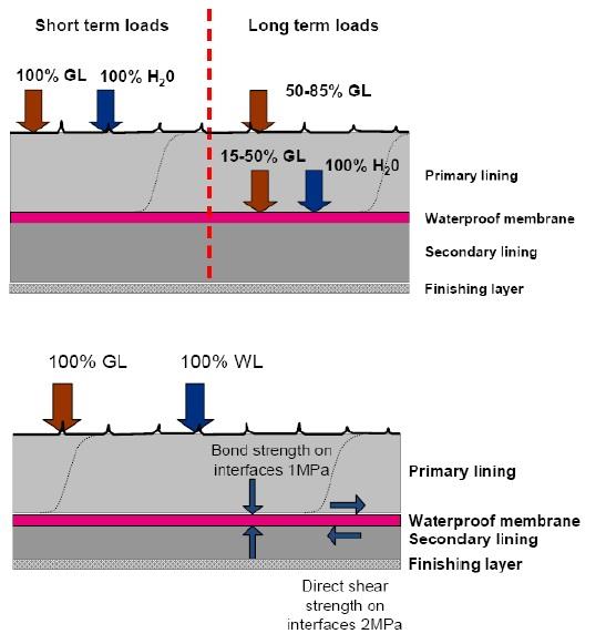
One promising design option, which stands out and attracts most attention at the moment, is the Composite Shell SCL. Composite Shell SCL, in the sense of tunnel construction, is the same as the Double Shell SCL, made of a layer of permanent sprayed concrete primary lining, a layer of spray applied waterproofing membrane and a layer of permanent sprayed concrete secondary lining. The major difference between them is that the former assumes a certain degree of adhesive and shear bond exists across the sprayed concrete-membrane interfaces while the latter does not. This difference makes the two lining design options behave in totally different ways under the soil and water pressures. For the Double Shell SCL, because there are no adhesive and shear bonds assumed at the interfaces, water could permeate through cracks in the primary lining and seep along the interface, applying pressure to the extrados of the waterproofing membrane. This has been the conservative design assumption, even though the test data from the manufacturers has shown a fully bonded behaviour (Holter & Nermoen 2011). The water pressure will be supported by the secondary lining alone in the long-term, becoming the main design case for the secondary lining thickness. By contrast, for the Composite Shell SCL, water permeating through cracks will be prevented from seeping along the interface, and most water will not reach the waterproofing membrane in its 120 years design life, providing that the SCL satisfies the maximum permeability requirements. (Jones 2012) The water pressure will be supported by both the primary and the secondary linings in the long-term, leading to a substantial thickness reduction in the secondary lining. In the case of the Composite Shell SCL, the thickness of the secondary lining could be as little as 60 mm (Holter& Nermoen 2011).The loading conditions for the Double Shell SCL and the Composite Shell SCL at the short and long-term are shown in Figure6.
Figure 6 Typical loading conditions for Double Shell SCL (top) and Composite Shell SCL (bottom)
A research programme, in collaboration with Mott MacDonald, Tam-Normet and University of Southampton and carried out by the author, is in progress to investigate the behaviour of Composite Shell SCL tunnels. As part of the testing programme, a series of compression, tension and direct shear tests have been carried out on samples cut from panels, built up from a sprayed primary layer, spray applied waterproofing membrane(TamSeal 800)and sprayed secondary layer. The aim of the tests has been to understand the fundamental properties of sprayed concrete-membrane bonding systems, especially the impact of the interface roughness and membrane thickness on strength and stiffness. The testing has reported that, for TamSeal 800 sprayed waterproofing membrane, the adhesive bond strength is around 1MPa and the shear strength is above 2MPa at the sprayed concrete-membrane interface. This test result has made the composite action feasible at the sprayed concrete-membrane interface. With further testing and numerical modelling analysis, a design guideline shall be developed for the Composite Shell SCL tunnels in the near future.
4.2 Further development in design methods
One possible area comes from the further understanding of the creep effect of early age sprayed concrete. It is understood that the creep effect is stress-dependent (Thomas 2008) and little information is currently available regarding this issue. An understanding of this issue could lead to more accurate modelling of the SCL at early age. The field of materials science continues to develop. In the future it is likely that macro-synthetic fibres will be widely used and that fully bonded composite action will be assumed in design using spray applied waterproofing membranes. The latter could significantly reduce the overall lining thickness.
Last but not the least, more back-analysis should be carried out so refinements can be made to the constitutive models for the ground and sprayed concrete as well as the 2D relaxation methodology. In order to do so, it is very important to determine the location and the techniques to install monitoring systems so that more reliable data will be available for back analysis. The Crossrail project represents a significant opportunity for the tunnelling industry to learn more and apply the benefits to future projects such as HS2 and Crossrail 2.5 Conclusion
The last twenty years has seen huge progress for sprayed concrete linings, including the shift from being a temporary structure to a permanent structure. Once the composite action across the sprayed concrete-membrane interface become a consensus in the tunnelling industry, the SCL design philosophy will experience another revolution, which sees the Composite Shell SCL replacing the Sacrificial Primary SCL and the Double Shell SCL, switching the main burden of the permanent structure from the secondary lining to the primary lining. The secondary lining will then act mostly as a supporting layer for the purposes of fire resistance and internal fixings.
References
Addenbrook, T.I., Potts, D.M., & Puzrin, A.M. (1997). The influence of pre-failure soil stiffness on the numerical analysis of tunnel construction. Geotechinique 47, No.3, 693-712
Addenbrook,T.L. (1996).Numerical analysis of tunnelling in stiff clay, PhD thesis, Imperial College, University of London
Annett, M. F., Earnshaw, G. & Leggett, M. (1997). Permanent sprayed concrete linings at Heathrow Airport. Proc. Tunnelling ’97. 517-534, London: The Institute of Mining & Metallurgy.
Atkinson, J.H. (2000). Non-linear soil stiffness in routine design. Geotechnique 50, No. 5, 487-508.
Austin, S & Robins, P. (1995). Sprayed Concrete: Properties, design and application, Bristol: Whittles Publishing.
Barton, N., Lien, R. & Lunde, J. (1974).Engineering classification of rock masses for the design of tunnel support. Rock Mechanics. 6: 4: 189-236.
Bernard, E.S. (2004). Creep of cracked fibre-reinforced shotcrete panels, Shotcrete: More Engineering Developments, Bernard (ed.), pp 47-58, Taylor & Francis, London.
Bernard, E.S. (2009).Design of fibre reinforced shotcrete linings with micro-synthetic fibres. Proc. Shotcrete for underground support XI.2009.
Chang, Y. and Stille, H. (1993). Influence of early age properties of shotcrete on tunnel construction sequence. Shotcrete for Underground Support VI, American Society of Civil Engineers, Reston, pp. 110-117
Curtis, D.J. (1976). Discussion on the circular tunnel in elastic ground, Geotechnique, vol. 26, No.1, pp 231-237.
Deane, A.P & Bassett, R.H. (1995). The Heathrow Express Trial Tunnel, Proceedings of the ICE -Geotechnical Engineering, Volume 113, Issue 3, pages 144 –156
Eadington, J & O’Brien, T (2011), Stiffness parameters for a deep tunnel –Developing a robust parameter selection framework. Proc. 15th European Conference on Soil Mechanics and Geotechnical Engineering. Athens, Greece.
EN 14487-1: 2005 (2005). “Sprayed Concrete —Part 1: Definitions, Specifications and Conformity”, British Standards Institution, London.
Eurocode 2 (2004).EN 1992-1-1:2004 “Design of concrete structures —Part 1-1: General rules and rules for buildings”, British Standards Institution, London.
Franzén, T. (1992). Shotcrete for underground support: a state-of-the-art report with focus on steel-fibre reinforcement. Tunnelling and Underground Space Technology, 7. No.4 383-391
Gasparre A (2005) -“Advanced laboratory characterisation of London Clay”. PhD Thesis. University of London.
HSE (2000). The collapse of NATM tunnels at Heathrow Airport. Health & Safety Executive Books, HMSO, Norwich.
Holter, K.G & Nermoen, B. (2011). Permanent waterproof tunnel lining based on sprayed concrete and sprayed-applied double –bonded membrane. Proc. World Tunnelling Congress 2011.
ICE (2004). Tunnel Lining Design Guide, The Institution of Civil Engineer, 184pp. London: Thomas Telford Publishing
Jardine, R.J., Symes, M.J.P.R. , Burland, J.B.(1984).The measurement of soil stiffness in the triaxial apparatus, Geotechnique, 1984, Vol:34, Pages:323-340
Jardine, R.J., Potts, D.M. , Fourie, A.B., et al,(1986).Studies of the influence of non linear stress-strain characteristics in soil-structure interaction, Geotechnique, 1986, Vol:36, Pages:377-396
Jones, B. D. (2007). Stress in Sprayed Concrete Tunnel Junctions. Ph.D. thesis. University of Southampton.
Jones, B.D., Thomas, A.H., Hsu, Y.S.& Hilar, M.(2008). Evaluation of innovative sprayed-concrete-lined tunnelling. Proc Inst. Civ. Engrs Geotech. Engng 161, 137-149
Jones, B.D. (2012). Waterproofing sprayed concrete tunnels. Tunnelling Journal, 2012, June/July, Page:35-36
Kusterle, W.A. (1997). New ecologically desirable sprayed concrete. Proc. Tunnelling ’97. pp 263-274, London: The Institution of Mining & Metallurgy.
Linney, L.F. & Essler, R.D. (1994), Compensation grouting trial works at Redcross Way, London. Grouting in the Ground. pp 313-326
Muir-Wood, A.M. (1975). The circular tunnel in elastic ground. Geotechnique. Vol.25, No.1. pp 115-127.
O’Rourke, T. D. (1984). Guidelines for Tunnel Lining Design. Technical Committee 011 Tunnel Lining Design of the Underground Technology Research Council of the ASCE Technical Council.
Peck, R.B. (1969). Deep excavations and tunneling in soft ground. Proc. 7th International Conference Soil Mechanics and Foundation Engineering, Mexico City, State of the Art Volume, pp. 225-190
Panet, M. & Guénot, A. (1982). Analysis of convergence behind face of a tunnel. Proc. Tunnelling’82, pp. 197–203. IMM, London.
Potts, D.M. & Zdravkovic, L. (2001). Finite element analysis in geotechnical engineering, vol. 2: Application. London: Thomas Telford.
Shuttleworth, P. (2001). Fire protection of concrete tunnel linings, Proc. 3rd Int. Conf. on Tunnel Fires and Escape From Tunnels, Washington DC, USA, 9-11 October, pp. 157-165.
Thomas, A. H. (2003). Numerical Modelling of Sprayed Concrete Lined (SCL) tunnels. Ph.D. thesis, University of Southampton.
Thomas, A.H. (2008). Sprayed Concrete Lined Tunnels. 264pp. Abingdon: Taylor and Francis Publishing.
Van der Berg, J.P., Clayton, C.R.I. and Powell, D.B. (2003).Displacements ahead of an advancing NATM tunnel in the London clay.Geotechnique, 53, (9), 767-784.
Wongsaroj, J., Soga, K. & Mair, R.J. (2007). Modelling of long term ground response to tunnelling under St James’s Park, London. Geotechnique 57, No. 1, 75–90.
-
Authors
Jiang Su BEng MPhil - Mott MacDonald
Mott MacDonald
Alun Thomas BA PhD - Mott MacDonald
Ramboll (formerly Mott MacDonald)
-
Acknowledgements
Tony Deane, Mott MacDonald
Chris Pound, Mott MacDonald
Ross Dimmock, Normet UK Ltd
Bethan Haig, Normet UK Ltd, for their contribution in the development of the design approaches
