A People Centred Design: Human Factors Integration of the Crossrail Route Control Centre
Document
type: Technical Paper
Author:
Zoe Cooper, Karen Wright
Publication
Date: 02/12/2021
-
Read the full document
Introduction
Pivotal to the safe, reliable and efficient running of Crossrail is the Romford Route Control Centre (RCC). The RCC is a dedicated control suite responsible for command and control of the Elizabeth Line Central Operating Section (COS). The infrastructure will be operated by Rail for London Infrastructure (RfLI) and the Crossrail Train Operating Company (CTOC) will be operated by Mass Transit Railway (MTR). The RCC brings together RfLI signalling and power control with MTR’s service delivery teams, operating an end-to-end service for the COS from one control room. This is leading edge in the railway industry, historically these stakeholders would operate from separate control functions. In relation to the RfLI signalling and power control, this has offered the opportunity for Traffic Managers to be multi-skilled and competent in both areas of control, allowing for flexibility within the control teams and enhanced understanding across both functions.
The RCC is located as a dedicated suite of rooms within the Network Rail new build Romford Rail Operating Centre (ROC). This includes an operational Control Room, Incident Room, Training Simulator Room and a number of additional ancillary rooms designed to support the main control area. The RCC is a complex, socio-technical system which brings together people, operations, management, control systems and physical equipment, all within the RCC environment. By recognising the interaction between these elements, an integrated approach to human factors and ergonomics in the design of the RCC has been crucial in supporting operator performance and reducing the risk for human errors.
The RCC Human Factors (HF) integration team have been responsible for ensuring a people centred design from identifying the early control room function requirements through to developing the concept design, detailed design and undertaking validation exercises during Dynamic Testing. By working collaboratively with Crossrail, RfLI and MTR, the RCC HF integration team have ensured that key stakeholder’s and end-user requirements have been identified, documented and met within the design. This paper discusses the approach to human factors undertaken to support the assurance case for Entry into Trial Running and describes the next phases of work during trial running and trial operations as the team start collating operational feedback from the live railway environment.
The RCC as a socio-technical system
The RCC workstream was developed to take a Human Factors (HF) approach to the design and development of the RCC and the Back-Up Control Facility (BUCF). The BUCF, located within the Tunnelling and Underground Construction Academy (TUCA) in Ilford, will enable key rail services for the COS in the event of an emergency situation where the RCC is not available.
The approach to HF work has followed the ISO Standard 11064 Ergonomics Design of Control Centres[1] which requires the RCC to be considered a socio-technical system constituting of a number of elements which all require to be developed and assessed as shown in Figure 1.
- A: Control suite layout
- B: Control room layout
- C: Workstation dimensions and layout
- D: Design of system displays and controls
- E: Environmental design
- F: Organisational and management systems design.
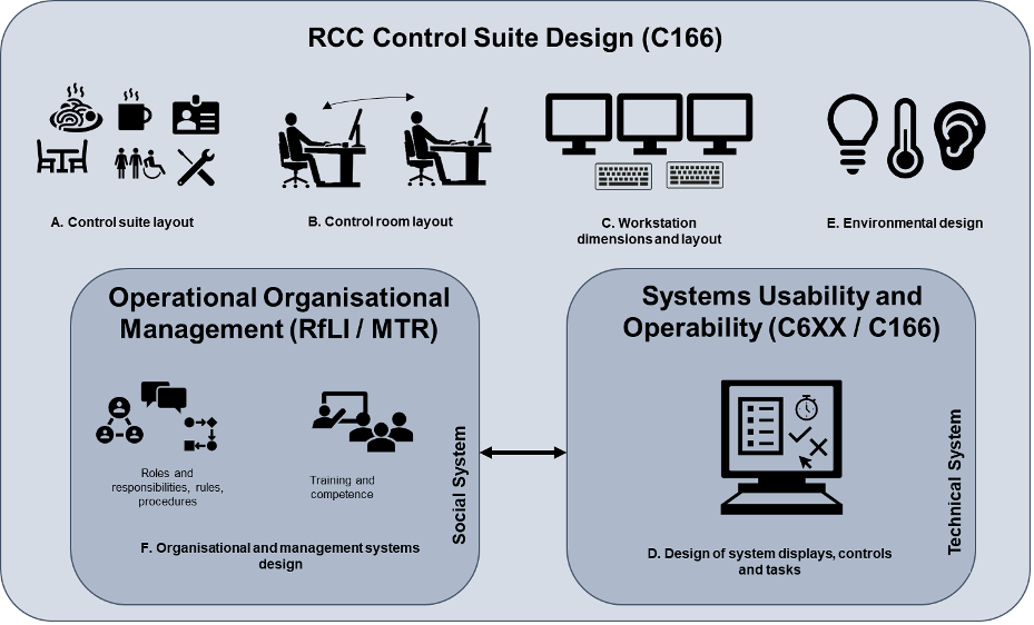
Figure 1. Elements of Ergonomic Design of the Route Control Centre (RCC)
Elements A, B, C and E referred to as RCC Control Suite Design are the responsibility of the RCC HF integration team.
Element D referred to as Systems Usability and Operability is the responsibility of the three individual Systemwide Contractors (C6XX) for single system use and the responsibility of the RCC HF integration team for integrated use of systems. The three Systemwide Contractor systems are as follows:
- C610 – Tunnel Ventilation System (TVS)
- C620 – Vicos Signalling System
- C660 – Central Management System (CMS) and Supervisory Control and Data Acquisition (SCADA), including traction and High Voltage (HV) power control
Element F referred to as Operational Organisational Management is the responsibility of RfLI and MTR.
For a successful socio-technical system, each sub-system or element must be sufficiently designed and developed whilst recognising and accounting for the interactions between the other sub-systems; essentially the interaction between people, technology and the environment.
An iterative design approach was taken for the RCC, with engagement from Crossrail, RfLI, MTR and Systemwide Contractors to validate the design at each key phase. The key activities are outlined in Figure 2 from definition in Phase 1 through to HF validation in Phases 2-
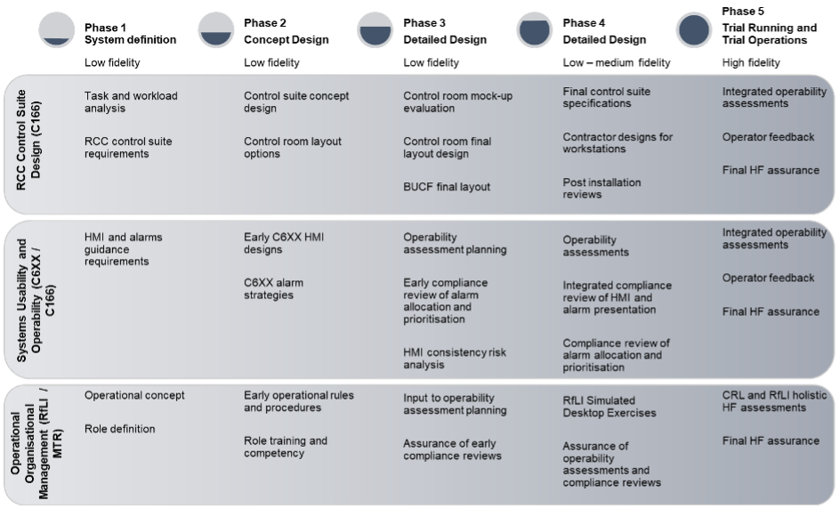
Figure 2. Iterative design approach for RCC
The fidelity of the HF validation exercises increased throughout the phases of work in line with the enhanced design and implementation of the control suite, systems, and operational and organisational rules and procedures.
Phase 1: System Definition
The RCC had a number of particular key requirements set out by Crossrail:
- A design that is a state of the art and unique working environment that includes technology and innovation to enhance user performance
- Provide a functional and ergonomic design
- Integration of Traffic Managers (controlling the infrastructure) and Crossrail Train Operating Company (CTOC) operators into the Crossrail working environment
- Ensuring there is minimal disruption to the operations of the railway while providing real-time information to the users of the system
- Design of a Back Up Control Facility (BUCF) to maintain the Crossrail service in the event of an emergency that immobilises the RCC
- Design of the building in co-ordination with Network Rail (NR), as well as co-habiting the building with Network Rail when it is operational.
A total of 869 HF design requirements were developed and agreed with Crossrail, RfLI and at the time CTOC representatives prior to MTR commission. These requirements covered
the physical design of the rooms and the system designs. The requirements were based upon:
- Baseline task analysis for the RCC roles
- User requirements from RfLI and MTR
- Ergonomic standards including BS EN ISO 11064 [1] and BS EN ISO 9241 [2]
- Alarm guidance including EMMUA 191[3]
- Ergonomics best practice.
Phase 2: Concept Design
Due to the integrated nature of the operational structure, conceptual layout options based on existing Control Rooms and innovative designs were developed. The advantages and disadvantages of each layout with particular reference to operator communication links were identified. 2D CAD models were drawn to provide a visual demonstration of each option as shown in Figure 3.
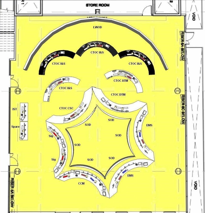
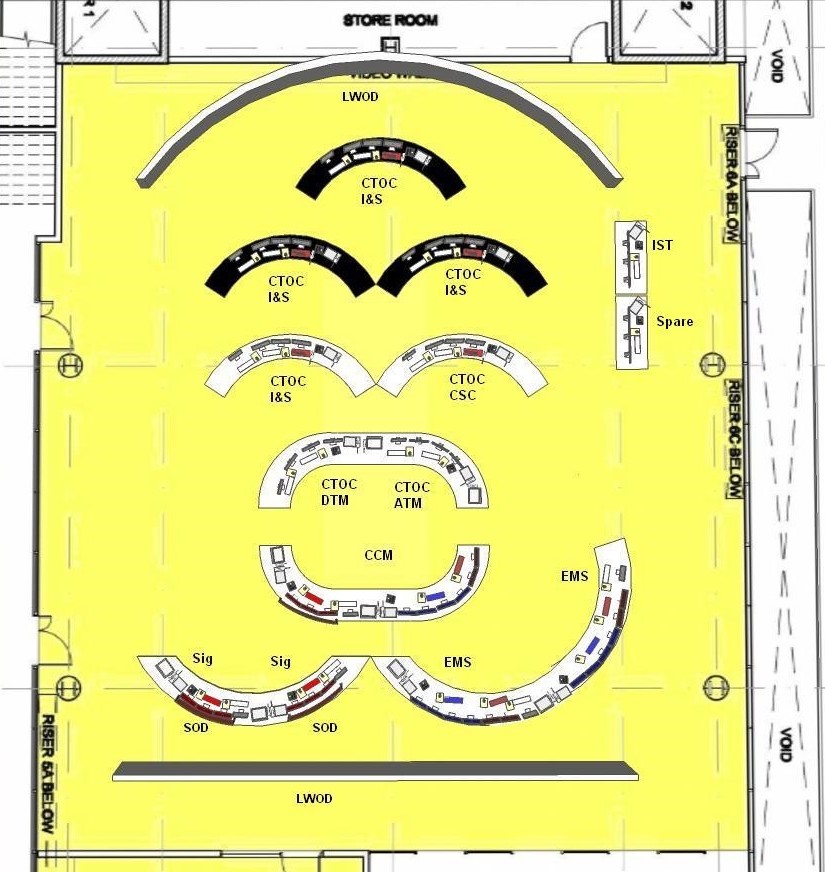
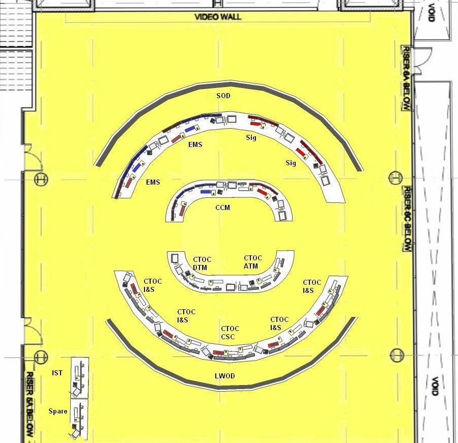
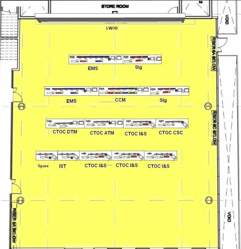
Figure 3. Initial layout options for the Crossrail RCC control room
The layout options were assessed in a design development workshop attended by key representatives from Crossrail and RfLI who chose the design that best fit the requirements previously defined. This process also enhanced and refined some of the operational layout requirements. This included the key communication relationships between operators. The five key relationships and their principle roles are listed below:
- Relationship 1- Signalling and train services
- Relationship 2- Infrastructure management
- Relationship 3- Operational management
- Relationship 4- Train and crew resourcing
- Relationship 5- Customer service and information.
These key communication links were central to the later design refinements as the conceptual design was developed further as shown in Figure 4.
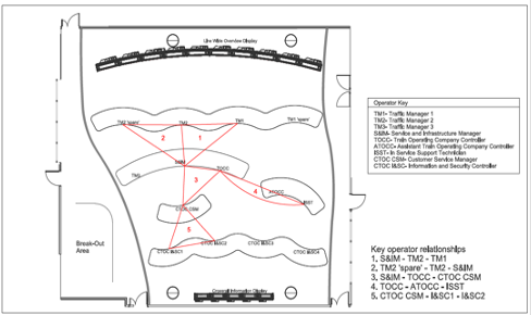
Figure 4. Key operator communication links in the RCC.
During the concept design stage, the three Systemwide Contractors were developing their early system designs and HF assurance strategies and plans. RfLI and MTR were further developing their roles, rules and procedures and beginning to look at training for the roles.
Phase 3 and 4: Detailed Design – RCC Control Suite
The detailed design was assessed using a full-scale, cardboard mock-up of the control room and training simulator room to provide validation of the final design (Figure 5). During the mock-up, the following ergonomic assessments were completed:
- Necessary operational staff adjacencies
- Necessary voice communication between staff
- Visual sightlines to on-screen equipment
- Visual sightlines to the LWOD and CID
- Visual sightlines between operators
- Readability of the proposed content on the overview displays
- Ergonomic postures for each operator position.
There was also an opportunity to run through operational scenarios with operational representatives playing the roles of operators. This was to verify the communication links between key relationships. A workshop to detail any amendments that could benefit the layout and further improve communication links between operators was held during the Mock-Up assessment and all participants accepted the final layout design.
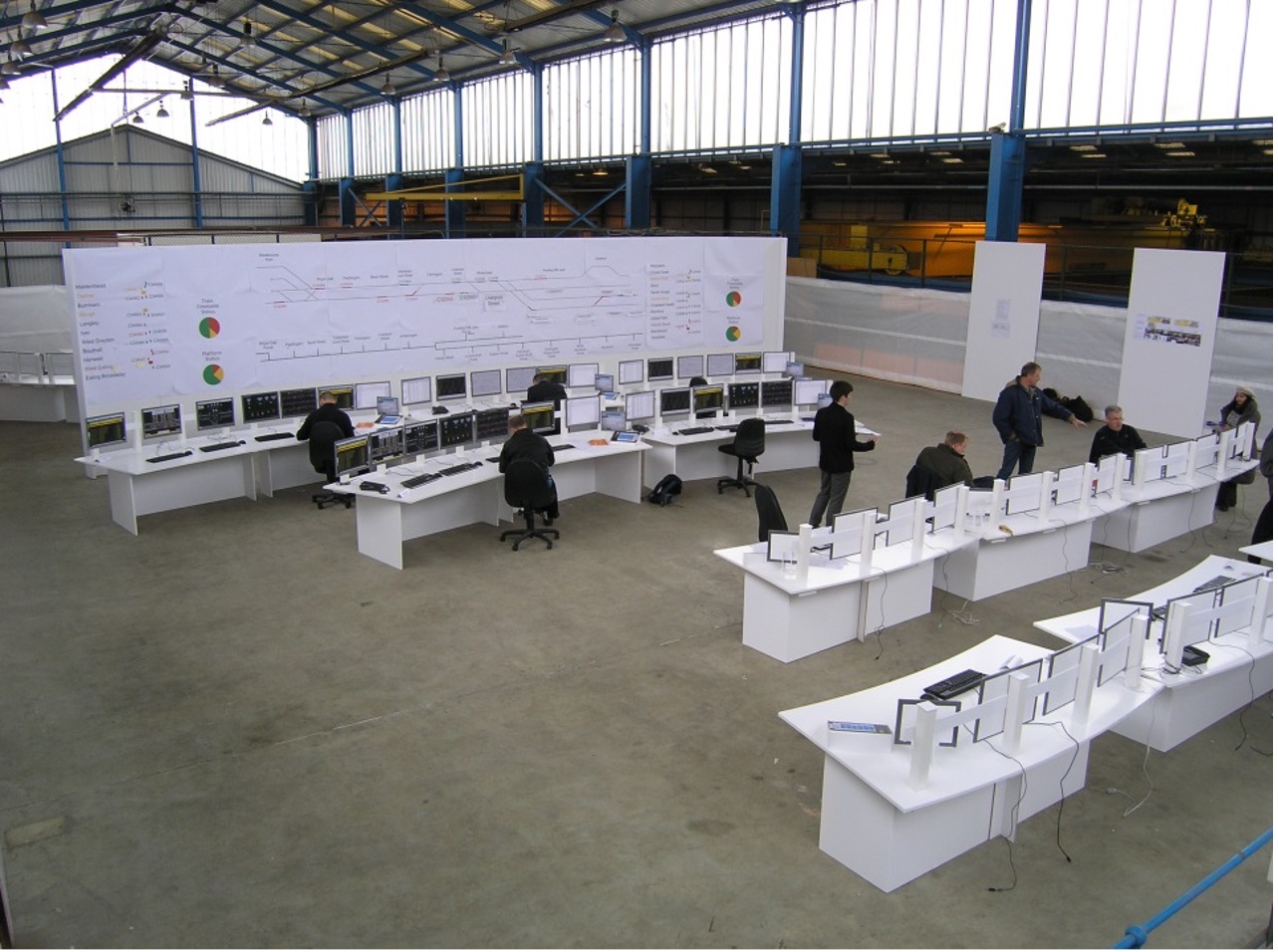
Figure 5. The full-scale mock-up of the Crossrail RCC
Following agreement of the final layout design, additional changes were identified by various parties, these included the additional role of the Customer Experience Delivery Manager (CEDM), the movement of the DCM and ISST workstations and inclusion of additional equipment for the newly appointed CTOC, MTR. This required further development of the final layout design to accommodate these changes to requirements.
Once the RCC and BUCF had been fully installed in line with the layout designs, HF engineers conducted a post-installation compliance review of the control suite and ancillary rooms against the HF design requirements.
Further to this, the RCC HF integration team involved end-users in a physical integration ergonomic review in the RCC (Figure 6). Crossrail ensured that the workstations were set up as per the designed equipment layouts for the purposes of the reviews. The review did not involve any end-user interaction with the systems but aimed to validate the RCC design for Entry into Trial Running, based upon equipment use (frequency and criticality) and communication links. The validity of the findings from the review were compromised as the participants were not all familiar with their roles, their systems, their equipment or the RCC environment. Therefore, these items are being reassessed as part of the integrated operability assessments during trial running. A similar exercise was conducted in the BUCF, with similar limitations identified in relation to familiarity with roles, systems and the BUCF environment. A number of HF issues were raised during these assessments but no design changes were recommended as a result of the assessment limitations.
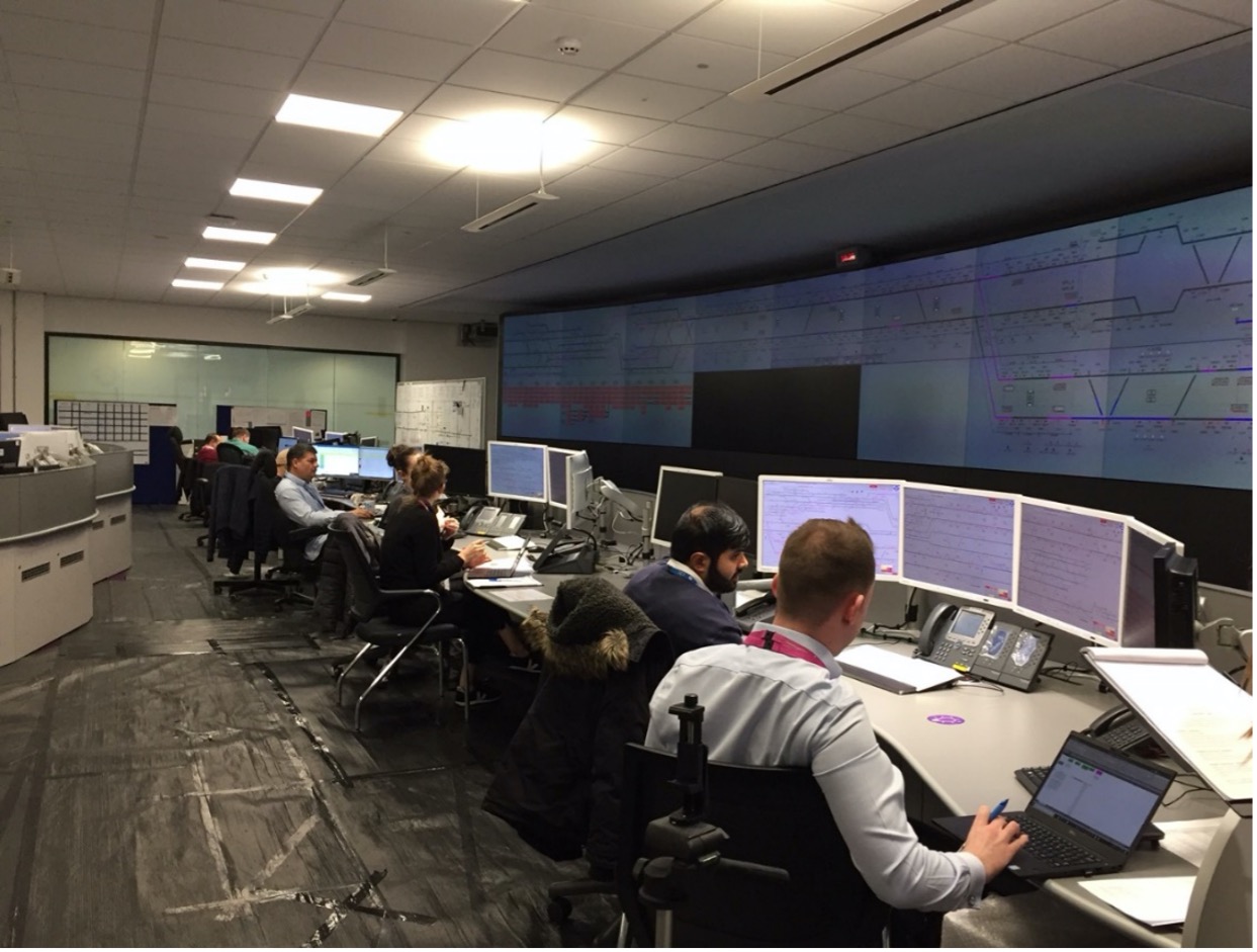
Figure 6. RCC Physical Integration Review
Phase 3 and 4: Detailed Design – System Usability
During phase 3 and 4 a series of HMI and alarm compliance reviews were undertaken across the three Systemwide Contractors. The mid compliance review identified a large number of gaps in evidence of non-compliances and partial compliances which were communicated to the Systemwide Contractors. The distribution of alarms to alarm priority bands for each role was not achieved by any of the Systemwide Contractors, and therefore it was deemed highly likely that the desired frequency of alarms would not be achievable and could lead to alarm flooding for certain roles when the systems are in operation.
Maintenance alarms had not been routed to the RTIM role, as this role had not previously been well defined, which meant that alarms had been routed to Traffic Manager 1 (TM1) and TM2 which they may not be responsible for.
The RCC HF integration team developed a revised alarm prioritisation and allocation matrix that could be used consistently by the three Systemwide Contractors and facilitated a series of alarm review workshops. The workshops involved the appropriate stakeholder representation from end users for Operations and Maintenance functions in RfLI. The workshops generated revised alarm priorities and role allocations for the alarms that demonstrated closer compliance to the requirements.
As part of the Entry into Trial Running compliance review, the RCC HF integration team reviewed all instances of partial or non-compliances across the three systems and used Predicted Human Error Analysis principles to review acceptability for integrated systems usability.
As a result of the compliance review, alarm messaging workshops were held with each Systemwide Contractor to ensure that alarm messaging was understandable by end-users and that common terminology was consistent across the systems.
Phase 3 and 4: Detailed Design – System Operability
Each Systemwide Contractor conducted operability assessments with end-users across a range of scenarios to validate the individual systems design.
Prior to trial running, RfLI delivered a programme of Simulated Desktop Exercises (SDEs) using the Vicos (signalling system) and Central Management System over several months to test procedures, maintain competence, and identify any operational issues arising from the scenarios tested.
The RCC HF integration team used two of these SDEs as an opportunity to carry out early integrated operability observations. The purpose of these observations was to identify any operability issues that led to additional workload demands. It is noted that the SDEs were conducted in a simulator setting and alarms were not functional.
The first exercise was focussed on train-based events and only affected TM1 using the Vicos system. The second exercise involved power faults and affected both the TM2 using the CMS system and the TM1 using the Vicos system.
The TM1 did not use the Timetable Editor function of the system during either of the scenarios, and instead manually routed trains from marker board to marker board. The manual routing of trains is time-consuming, and potentially error-prone, and not as per the operational design. The need to conduct further operability assessments using the Timetable Editor function was raised.
The RCC HF integration team had planned to undertake further SDE observations prior to trial running to observe how the operators engage with multiple systems, however as the systems are not integrated on the simulator this was not possible.
Following the SDEs, a period of Systems Integrated Dynamic Testing (SIDT) was carried out by Crossrail in the RCC control room. During this period, the TM1 was controlling the Vicos system but all other systems were being operated by Crossrail test engineers. The TM1 was not operating the signalling system under RfLI rules and procedures; they were working under the Crossrail testing rules and conditions. Therefore, although SIDT included integrated systems scenarios, the RCC HF integration team could not undertake the HF integrated operability assessments during this period as the testing conditions were not realistic for the operational railway and therefore results would not support the assurance case for integrated operability.
Phase 5: Trial Running and Trial Operations
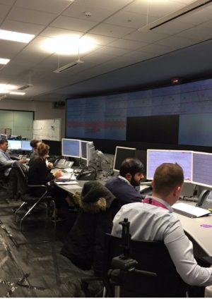
The integrated operability assessments are currently being undertaken during trial running as this is the first opportunity where the live systems are being controlled by trained TMs/operators working under RfLI and MTR rules and procedures in the RCC.
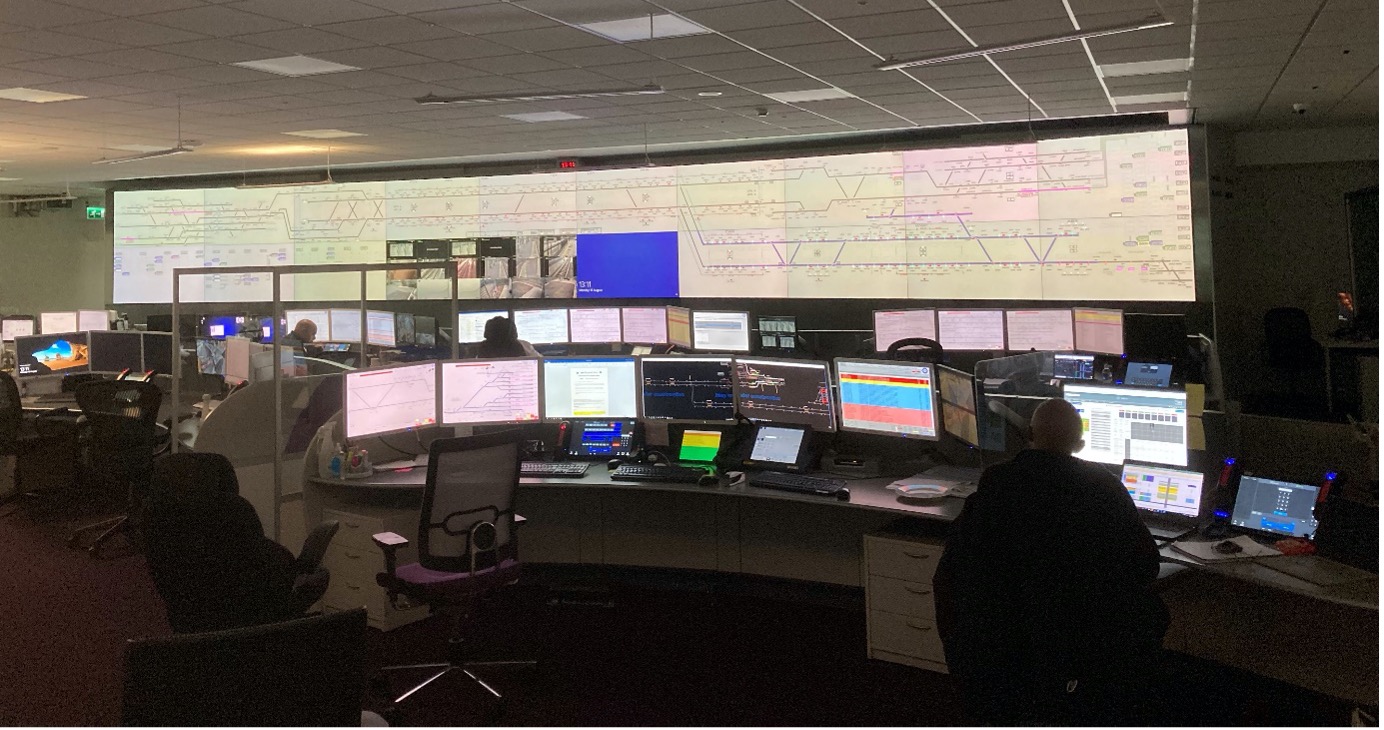
Figure 7. RCC control room during trial running
The integrated operability assessments involve scenarios that will test the integrated operation of the Systemwide Contractors systems, communications between operators in the control room and the physical layout of the workstations and equipment within the control room. The operators’ objective performance using multiple systems as well as their subjective views will be captured and confirmed that they meet the agreed acceptability criteria.
The RCC HF integration team facilitated a series of meetings and workshops with the Crossrail Trial, Testing and Commissioning (TT&C) Team, RfLI and MTR stakeholders and end-users to ensure that appropriate scenarios are planned and executed during trial running to support the HF assessments. The scenarios for HF assessment have now been agreed and final details of the test scripts, programme of assessments and individual scenario plans are being progressed.
The first four weeks of trial running were expected to be RfLI’s IM ramp-up period where RfLI would have taken control of the railway and been ensuring that it was working as expected prior to entering the main period of trial running. This four-week period was expected to provide the opportunity to confirm that operations were running as expected from an integrated HF perspective and to identify any initial HF issues ahead of the main trial running period when more complex scenarios will be executed. Unfortunately, the IM Ramp-Up period and the programme of integrated operability assessments was delayed by the introduction of a four-week maintenance period at the start of trial running. At the time of writing, the RCC HF integration team have observed eight scenarios in the RCC (possessions and isolations, splitting of TM1 workstation, damage to OHLE and train rescue) and therefore no formal analysis of the data has been reported on yet as the reporting requires observation of multiple scenarios across a range of normal, degraded and emergency scenarios to be able to draw conclusions on the validation of the relevant requirements and issues resolution. It is expected that as the trial running period progresses there will be further opportunities to undertake the scenario observations and build a stronger assurance case for Entry into Trial Operations.
As well as the evidence collated as part of the integrated operability assessments, the RCC HF integration team are also managing an end-of-shift feedback form through which the operators are encouraged to report any HF-related (or other) issues. The feedback from this form is reviewed and distributed to the relevant stakeholders on a fortnightly basis. The RCC HF integration team are also undertaking observations of normal running timetable days in the RCC.
The RCC HF integration scope of work is focused on the interaction of users with the Crossrail systems that have been supplied. However, the RCC operators also interact with RfLI and MTR-supplied systems and their workload levels will also be affected by their operational procedures, training and competency. The Crossrail and RfLI HF Leads have developed a plan for overall workload assessments during trial running.
Further integrated operability assessments are planned for during the trial operations period. The methods and approach to the assessments will be the same as for the trial running assessments. It is expected that these assessments will include some system aspects that were not ready for trial running, e.g. inclusion of incidents at stations. Trial operations will offer the highest level of fidelity for the assessments whereby scenarios will be undertaken alongside normal timetable running with volunteers on the trains and in stations.
Lesson learned
In summary the main lesson learned with regard to HF integration of the Crossrail RCC has been about timing.
There was a strong start in collaboratively defining the HF requirements for the control suite and the systems usability. The RCC designs were driven by the NR programme to complete the build of the ROC. This meant that there were some late but significant changes to the final room layout as decisions had to be made before the CTOC requirements were fully matured which occurred with the commissioning of MTR. This has meant that the planned 25% capacity built into the design has already been largely used. In terms of the systems usability the three different Systemwide Contractors were on very different development timelines making it difficult to co-ordinate the development of consistency across the systems. Furthermore, the late access to alarm lists meant that assessing and resolving the issue of alarm frequencies from a role perspective (rather than a system perspective) caused significant re-work and was only partly implemented for trial running. Part of this issue could be put down to the lack of apparent buy-in to the need for integration of HF across the suppliers.
Performing integrated operability assessments when all parts of the socio-technical system were in use was not able to be performed until a much later time in the programme than was anticipated. It had been hoped that a gradual increase in fidelity of integrated operability assessments would have been achieved in the lead up to trial running, however this was not feasible. The physical integration reviews undertaken prior to trial running were limited in fidelity as the end-users were not yet familiar with their roles and the RCC / BUCF environments. Therefore, although feedback was received from these assessments, no changes to the design could be made for Entry into Trial Running as there was little evidence to support them.
In the future, in order to try and enhance end-user training and familiarity ahead of the operations testing periods, an integrated-systems simulator should be available for use by the end-users. This would support the integrated operability assessments, allowing the end-users to experience the use of integrated systems ahead of operational testing and enhance other operability areas such as alarm design and understanding system behaviour. This would also require the design development of the individual system suppliers to be closer aligned, further enhancing the HF assurance for integrated systems design.
References
[1] BS EN ISO 11064-1:2000 Ergonomic Design of Control Rooms – Part 1: Principles of the for the Design of Control Centres
[2] BS EN ISO 9241 Ergonomics of human-system interaction (multi-parts)
[3] EMMUA 191 Alarm systems –a guide to design, management and procurement, ISBN 085931 155 4
-
Authors