Application of the Observational Method on Crossrail projects
Document
type: Technical Paper
Author:
Ying Chen, Duncan P Nicholson BSc MSc DIC CEng MICE, Peter Ingram, Stuart Hardy, Hock Liong Liew BEng MEng PE(Civil) Singapore, Imran Farooq BSc MSc CEng MICE MASCE, Giovanna Biscontin
Publication
Date: 10/11/2015
-
Read the full document
1. Introduction
The Observational Method (OM) was first successfully applied in geotechnical engineering by Terzaghi and had been formulated and developed as the ‘learn-as-you-go’ method (Terzaghi & Peck 1967). In the 9th Rakine lecture, a more formalised methodology and the name ‘Observational Method’ were introduced by Peck, who provided a distinct and novel design approach to manage risk (Peck 1969). The potential for savings of time and cost by applying the OM on engineering projects without compromising safety has been widely reported, such as the Channel Tunnel Rail Link (Young & Ho, 1994). The OM has been adopted and used in several countries, for example the UK with CIRIA report 185 (Nicholson et al. 1999), France with the Irex-RGCU guidelines by Allagnat (2005) ‘La Methode Observationnelle pour le dimensionnement interactif des ouvrages’ (2005), German Standard DIN 1054:2005-I Verification of the safety of earthworks and foundations and Dutch CUR document 166: sheet pile construction. In Eurocode EC7 (EN1997-2004), the OM is listed as one of the acceptable design methods.
The research on which this paper is based has been carried out as part of ‘Crossrail lessons learnt’ for the Crossrail project. The purpose of the paper is to use the Crossrail case histories to demonstrate a newly developed framework for the OM approach applied to deep excavations. The new framework is part of the CIRIA C760 (revision to CIRIA C580) due for completion in 2016 (Gaba et al.).
2. A new framework for the OM approach application to deep excavation
Historically, Peck, (1969) defined two situations where the use of the OM is appropriate:
- “Ab initio” approach – OM adopted from inception of the project. Peck recommended adopting most probable conditions and then introducing contingencies when required. This is an “optimistic” application of OM.
- “Best-way-out” approach – OM adopted after the project has commenced and some unexpected event has occurred or whenever a failure or accident threatens or has already taken place, the OM may offer the only satisfactory way out of the difficulties. This is a “reactive” use of the OM to an adverse event.
Since Peck’s Rakine lecture, further study on the implementation of the OM has been carried out. The OM was defined in detail in CIRIA 185 (1999) by Nicholson et al. This concentrated on the Ab initio approach. It recommended that a characteristic initial design, consistent with current codes should be carried out initially. A design would then be made using most probable parameters. If the monitoring data showed the characteristic design to be conservative then the design would be progressively modified to the most probable design. This is the “cautious” Ab initio approach.
At Crossrail, the OM was introduced into excavations after construction was started using conventional designs. The initial review of construction records showed that a saving in time and costs could be made. In this case the term “Best way out” is not appropriate because a “pro-active” rather than “reactive” use of the OM is being proposed. A more general term “Ipso tempore” – at the moment is suggested by the CIRIA C760.
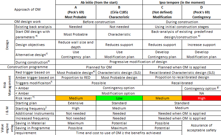
Based on the discussions and case histories of the OM, a framework for the OM approach has been developed for application of the OM to deep excavations as shown in Table 1. A detailed discussion on this framework will be presented in a future paper which is under preparation (Chen et al. 2016).
Notes:
a) Characteristic design using characteristic values as defined in EC7.
b) For Ipso tempore approaches, the start of OM design using parameters calibrated from back-analysis of predefined design (using characteristic parameters) in initial excavation stages.
c) Contingency plan is a design adopting characteristic parameters, modification plan is a design adopting most probable parameters.
d) Progressive modification is applied when more data are available to back-analyse and feedback to the design.
e) In Ab initio-A approach, the red trigger is used to decide if the alternative design will be adopted for the next construction stage. After switch to alternative design, the red trigger values should be redefined by characteristic design (SLS).
f) Trigger values will depend on the ‘discovery-recovery’ contingency plans being used and not simply taken from the calculated values.
g) For Ipso tempore-D approach, to prevent a SLS or ULS failure occurring, contingency or emergency plan will be required.
h) Risk level for each OM approach is indicative based on a comparison between OM approaches.
i) Frequency recommendation: high=hourly to daily; medium = daily to weekly
j) Contractual and communication concerns are excluded in this OM approach frame table.Table 1 Summary of the Ab initio and Ipso tempore approaches for applications of the Observational Method
3. Crossrail case histories
The OM has been successfully applied to a number of Crossrail deep excavations and the project is therefore an ideal example to demonstrate the application of the OM approaches defined in Table 1. Examples have been listed which demonstrate the four methods of each of the OM approaches as described in the C760. Of these methods, two are demonstrated using case histories from previous projects, Batheaston-Swainswick Bypass (Nicholson et al. 1998) and a deep basement excavation with top-down method (Ikuta et al., 1999). One example is from an under construction project, the Victoria & Albert museum excavation. Three case histories from the Crossrail project are demonstrated using the new defined Ipso tempore-C (modification) OM approach. The following sections of this paper describe the relevant case Crossrail histories. These are summarised briefly below:
- Ab initio-A (most probable): Batheaston Swainswick Bypass excavation (Not discussed in this paper)
- Ab initio-B(characteristic): Top-down deep basement excavation (Not discussed in this paper)
- Ipso tempore-C (modification):
Tottenham Court Road (TCR) station excavation, Western Ticket Hall (WTH)
Canary Wharf Crossrail Station (CWCS) excavation, head walls
Liverpool Street station Moorgate Shaft (LIS-MS) excavation - Ipso tempore-D (contingency): Victoria & Albert museum excavation (Not discussed in this paper)
Back-analyses of the case histories in this paper have been carried out by using Oasys FREW version 19.2 (2D), unless otherwise stated. The maximum predicted wall deflection and the measured wall deflection were compared at key excavation stages, demonstrating the benefits of the OM approach for each case history.
3.1 Tottenham Court Road Western Ticket Hall
Introduction
The excavation of the Western Ticket Hall (WTH) box at Tottenham Court Road (TCR) station of the Crossrail railway project in London was undertaken using bottom-up construction to minimise the duration of excavation, see Figure 1. This decision was taken to facilitate the earliest possible construction of the base slab and preparatory sprayed concrete lining (SCL) tunnelling works in advance of the arrival of the twin tunnel boring machines (TBMs).
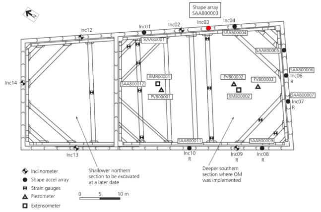
Figure 1 TCR-WTH instrument layout plan (Yeow et al. 2014)
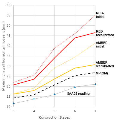
Figure 2 Triggers for TCR-WTH diaphragm wall
OM application
Before construction started the Contractor carried out a Value Engineering study which identified an opportunity for the application of the OM. This led to increased instrumentation to provide more comprehensive real time monitoring. The possibility of modifying the conforming design at early stages in the construction sequence was identified by using the OM approach. Collaboration was required between the client, contractor and designers.
The OM was used to eliminate the lowest level of temporary propping originally designed to support the retaining walls. This was after the excavation work started and was aimed to reduce the support, therefore this case can be categorised as an Ipso tempore-C (modification) OM approach – a “proactive” approach as listed in Table 1.
Stage Description Start* End* 1 Excavate to +121.6mTD 09/05/2012 16/05/2012 2 Installation P1 prop & excavate to +116.4mTD 20/06/2012 27/06/2012 3 Installation P2 prop & excavate to +111.1mTD 18/07/2012 25/07/2012 4 Installation P3 prop & excavate to +108.3mTD 08/08/2012 15/08/2012 5 Installation P4 prop & excavate to +101.2mTD 05/09/2012 – 6 Installation P5 prop** & excavate to +96.8mTD 21/09/2012 – (Local trench excavation to +95.4mTD) 26/09/2012 26/09/2012 7 Construct the base slab 29/09/2012 – *start and end dates are indicative dates for the excavation only
**prop P5 had been eliminated in the actual construction sequenceTable 2 Summary of construction sequence to casting of base slab (after Yeow et al. 2014)
Evidence to support the implementation of the OM became available at the end of stage 3 of construction, where the measured maximum wall deflection was 13mm compared with the predefined design deflection of 23mm, (see Figure 3). The stage 3 wall movements were back-analysed using most probable parameters assessed from a review of the site investigation data and the as-built construction details. The most probable predicted deflections for stage 3 excavation are shown in Figure 3, and it can be seen that they compare well with the measured deflections. The model was then run for the remaining excavation stages and the final predicted movements with no lowest level of temporary propping as shown in Figure 4, together with the predefined design predicted movements with the temporary props.
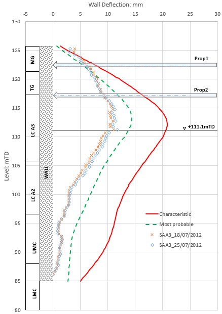
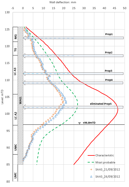
Figure 3 Greatest deflection profile at end of stage 3 Figure 4 Revised construction sequence eliminating prop P5, wall deflection profile at end of excavation stage Contingency measures were designed and an OM implementation strategy was set up to closely monitor and verify performance of the works. The recalibrated trigger values for subsequent stages after the back-analysis at stage 3 are shown in Figure 2 together with the measured data.
Benefits of the OM approach
The Ipso tempore-C (modification) OM approach was implemented during construction of Crossrail TCR station WTH box. This enabled the elimination of the P5 level temporary prop, leading to a critical path programme saving of 4 weeks and a £715,000 reduction in cost. (Yeow, et al. 2014)
3.2 Canary Wharf Crossrail station head walls
Introduction
Canary Wharf Crossrail station (CWCS) was constructed within the West India North dock covering an area of approximately 260m × 25m to 30m. The conforming design adopted a complex arrangement of Giken tubular piles with RC infill piles tied back to anchor piles behind the retaining wall forming a temporary cofferdam. In areas where installation of anchor piles was not possible, a cantilever retaining wall and berm were adopted. Details of the cofferdam wall design can be found in Yeow et al. (2012) and Travers & Yeow (2013).
OM application
During construction, a comprehensive array of monitoring instruments was used to capture deflections of the walls, piles, movements of the capping beams and tie forces. Those instruments were carefully read to establish baselines. At the same time, the excavation was carefully recorded. An Ipso tempore-C (modification) OM approach was applied: the design parameters were back-analysed using the monitoring data from early stages of excavation. Prior to excavating to the final formation level – excavation to -4 slab, a set of most probable parameters was derived to review the subsequent construction sequence for headwalls. This led to the removal of the lower-level berm and inclined props for the excavation to the final base-slab level. The estimated associated cost saving was approximately £500,000 in addition to substantial programme savings.
Benefits of the OM approach
This Ipso-tempore-C (modification) OM approach in the case of the CWCS head walls is a good example of using the new framework for OM approach in excavations. Based on the initial OM approach by Peck (1969), it is arguable whether this case history could be an “Ab initio” or “Best-way-out” method application. The concept of OM was considered at post-tender design development prior to commencing the construction work. However, a fast construction design for CWCS did not allow a full scale OM design to be developed prior to construction. The interactive involvement of client, designer and contractor, together with well-established baseline readings for the monitoring instruments and a clear excavation record provided an opportunity for OM implementation at later excavation stages. This proactive use of the OM has proven to be a success.
3.3 Liverpool Street station – Moorgate Shaft
Introduction
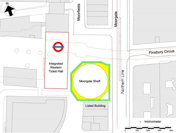
The irregular shaped Moorgate Shaft (MS) has been constructed at Liverpool Street Station (LIS). It is about 35m×35m in plan and extends approximately 42m below street level, see Figure 5 & Figure 6. Shaft construction was undertaken using the top-down construction technique by a 1.2m thick diaphragm wall with 7 levels of reinforced concrete ring beams and 2 levels of temporary steel props in the initial design. The north-south section differs from the east-west section which is supported by two additional temporary cross walls (1.2m thick unreinforced concrete panels) and a pair of slab strips (3.0m wide by 1.5m deep) in the initial design, to minimise wall deformation and protect nearby assets rather than for a ULS design requirement.
The removal of existing piles at the MS site had delayed the shaft construction programme by 11 months. To mitigate the delay, a reanalysis of the shaft has been carried out using FLAC 3D based on non-linear soil parameters and utilising a granted concession against Crossrail Engineering Design Standards (CEDS) to allow use of undrained conditions on the active side for fine grained soils. The reanalysis confirmed the lowest temporary prop at +76.0mTD could be omitted. Further value engineering review based on the reanalysis, identified further potential programme-saving measures: i) omission of temporary propping at +80.5mTD; ii) combining excavation stages for ring beams 4 and 5; iii) combing excavation stages for ring beams 6 and 7; iv) omission of the slab strips. The reanalysis of the shaft was discussed in detail by Farooq et al., (2015).


Figure 5 LIS-MS site plan (Faooq et al., 2015) Figure 6 Indicative instrument layout plan for LIS-MS OM application
The OM was used as part of a defined verification process which was a variation of progressive modification methodology (as defined in Powderham, 1998). The OM was agreed to be used at three selected Verification Points (VP) during excavation, to provide explicit safety assurance and reassure external stakeholders that project risks would be minimised. The innovative verification process (Farooq et al., 2015) in the MS confirmed those potential programme-saving measures at the VPs.
The redesign was carried out after the diaphragm walling and the first two excavation stages were completed, therefore, the MS case history is classified as Ipso tempore. Given the bespoke application of the OM approach detailed in Farooq et al., (2015), the approach here was not strictly Ipso tempore-C or D approach. However, as the overall proposed scheme was a proactive progressive modification where changes were only positive to the construction cost and programme, it can therefore be classified as Ipso tempore-C (modification). It could be argued that this application of the OM could also be considered as the Ab initio-B (characteristic) OM approach, as a full scale of preliminary ‘most probable’ redesign was completed prior to the potential measurements commencing in the field (although most probable rather than characteristic parameters were used in the initial re-design). This example serves to demonstrate the fluid nature of the boundaries between the different methods.
In the verification process, the pro-actively and progressively modified analyses used the state-of-the-art A* soil model as outlined by O’Brien et al., (2011 & 2013) in response to observed behaviour. This was a fluid real time assessment and the designer had to consider not only uncertainties in ground behaviour, but also the anticipated structural behaviour (such as the irregular shape of the shaft and ring beams as well as the efficiency of the cross walls) together with the uncertainties associated with adjacent concurrent construction activities (for example permeation grouting and SCL tunnelling work). The implementation of the process was discussed in detail by Farooq et al., (2015) and therefore will not be discussed further in this paper.
Stage Description Start1 End1 1 Installation capping beam & Excavate to +106.5mTD 24/10/2013 25/11/2013 2 Installation RB1 & excavate to +100.3mTD 16/12/2013 11/01/2014 3 Installation RB2 & excavate to +94.4mTD 17/03/2014 09/04/2014 4 Installation RB3 & excavate to +89.7mTD 5 Installation RB4 & excavate to +87.6mTD – – 5* (Alter.)2 Installation RB3 & excavate to +87.6mTD 07/05/2014 17/05/2014 6 Installation RB5 & excavate to +85.4mTD – – 7 Installation RB6 & excavate to +83.5mTD – – 7*(Alter.)2 Installation RB4, RB5 & excavate to +83.5mTD 28/06/2014 02/07/2014 8 Installation RB7, slab strips3 & excavate to +79.1mTD – – 8*(Alter.)2 Installation RB6, RB7 – – 9 Installation T23 & excavate to +71.3mTD – – 9*(Alter.)2 Excavate to +71.25mTD 22/08/2014 02/09/2014 10 Construct the base slab - start and end dates are indicative dates for the excavation stage only in line with the actual construction sequence.
- the alternative construction sequence (italic) confirmed by the OM during verification process.
- the slab strips and the temporary prop T2 at +80.5mTD were eliminated in the actual construction sequence.
- o to 600mm further dig have been included in the actual excavation to cast blinding layer and construction purpose.
- the detailed construction sequence refers to Farooq et al., 2015.
Table 3 Summary of construction sequence for the Moorgate Shaft – up to casting base slab stage
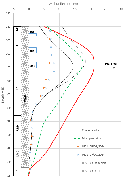
Figure 7 North wall deflection profile at excavation level of +94.4mTD

Figure 8 North wall deflection profile at final excavation level of +71.3mTD
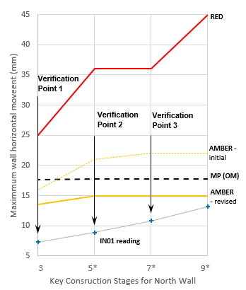
Figure 9 Triggers for LIS-MS north wall
The north wall as an example was selected to carry out a 2D back-analysis for this paper using FREW representing the north-south section and demonstrating the Ipso tempore-C (modification) OM application, which has considered the site constraints to the other walls as shown in Figure 5: the Northern Line tunnel less than 5m from the east wall, listed buildings immediate to the south wall and the existing Moorgate station ticket hall to the west. It should be noted that the verification process was based on using FLAC 3D model which had covered the above site constraints. The FREW analysis is included in this paper to demonstrate a 2D set of results for comparison purposes. A summary of key excavation stages and the alternative construction suggested by the redesign and confirmed by the OM at VPs is presented in Table 3. The 2D FREW back-analysis model has referenced to Table 3 for construction sequence.
Monitoring data was reviewed at three VPs corresponding to three excavation levels (at 94.19mTD, 87.35mTD and 82.9mTD) and wall movement projections produced using FLAC 3D and assessed to the bottom of the excavation at each VP stage to ensure the alternative construction sequence was applicable. Figure 8 shows the wall horizontal deflections at final excavation (stage 9) with a formation level of +71.3mTD.
A good match is seen between FLAC and measured results and also in the lower part of the wall between the measurements and the predictions using most probable parameters in FREW. However, this simplified 2D FREW back-analysis model is not able to capture the 3D effects from the MS geometry modelled by the FLAC 3D model referred to Farooq, et al., (2015). The north wall deflection profiles from the FLAC 3D model were shown in the figures, which were the actual prediction used to enact the Ipso tempore-C (modification) OM approach in the MS case history.
The triggers against the measured movement from key excavation stages are shown in Figure 9.
East Wall
For the MS east wall, the wall movements were initially minimised by installing two cross walls, see Figure 6, to control the movements of the adjacent Northern Line tunnels within the trigger limits. During the verification process at LIS-MS, it was noted that the east wall projected movements could lead to a potential amber trigger level breach when the excavation reached the bottom at 71.3mTD. This projection was due to uncertainty in modelling the east wall: the irregular shape of the shaft, inefficient ring beam geometry, concurrent adjacent grouting works on the east side, and difficulty in accurately predicting east-west cross wall stiffness/behaviour. To capture the uncertainties listed above a bounded approach for both soil and structural elements (such as ring beams, cross walls and diaphragm wall) was adopted for the analysis. The potential breach of the east wall amber trigger (due to lower bound analysis) and its consequent effects on the northern line tunnel were reassessed and accepted by the LUL (although eventually the original trigger levels were never breached during construction).
As the verification process progressed the analysis was refined until all completed construction stages could be replicated. Although the observed structural behaviour was at the lower end of the bounded parameters (i.e. pessimistic) in the model, the soil behaviour was at the upper end of the bounded parameters. The three phase verification process allowed the OM to be applied to modify the 3D model and each stage was fully assured by Cat III checker, with a best way out option available at each stage if unfavourable results were generated.
Given the unusual structural behaviour, particularly on the east wall, further contingency measures or best way out options were discussed and considered with the client during the verification process, such as suspension of prop omission, or less onerous propping. However, those measures were not needed, as by the end of the verification process there was a high level of confidence that the projected movements would stay within accepted trigger limits. Within the LIS-MS excavation, due to the speciality of the east wall, it is considered that the Ipso tempore-D (contingency) OM approach classification could have been applied for the MScase history if the best way out options/contingency had been implemented. The approach used at MS ensured that the safety requirements of nearby structures during the shaft excavation and the construction were understood at all stages of excavation.
Benefits of the OM approach
The verification process with the OM design approach was successfully implemented for construction of Crossrail LIS – MS. This enabled the construction programme to be accelerated by the elimination of the temporary prop at +80.5mTD and slab strips as well as the combination of excavation stages and overcoming the potential 11month delay. The OM application had not only made the construction faster but also safer by omitting the temporary propping, and reducing the number of construction stages. An additional benefit was that all parties had to work collaboratively throughout the process which facilitated communications and improved understanding of risks and opportunities.
4. Summary
The successful use of the OM in the Crossrail excavation case histories presented, shows that the OM can be used in the design of excavations to achieve savings in both time and costs. The OM approach was adopted at TCR-WTH after major excavation, leading to 4 weeks saving in programme and £715,000 in cost. It is estimated that if the OM approach had been adopted as “Ab initio”, the potential additional saving in material costs would have been between £350,000 and £500,000 under an associated design fee of approximately £50,000. The implementation of the OM requires full confidence in the design, construction approach and the active collaboration of all involved parties. The speed of the OM design is another key concern in the OM application. The OM case history of the CWCS head walls gives an example of the flexibility of the OM in adapting to the situation. The OM implementation at LIS-MS construction managed to achieve a construction programme saving. It also serves to demonstrate the fluid nature of the boundaries between the different OM methods. At the same time, it enabled the reassessment of unusual wall deflections of the east wall to ensure the safety requirements of a third party asset were satisfied so that the construction suspension period was minimised.
These Crossrail excavation case histories show that the revised framework for the OM approach from the C760 is applicable to excavation works. Potentially, this framework can also be applied to extended geotechnical engineering design: tunnel excavation, deep foundations and embankments, which will need additional support from the OM case histories for these applications.
Acknowledgements
The authors would like to thank Tony O’Brien from Mott MacDonald, and Mike Black and Peter Cracknell from Crossrail Ltd for their kind help on case histories and permission to publish the data presented. The authors would also like to thank their colleagues at Arup and Professor Kenichi Soga from the University of Cambridge for their contribution during the case histories study and compilation of this paper.
References
Terzaghi K. & Peck RB (1967) Soil mechanics in geotechnical engineering Practice, 2nd Edition John Wiley & Sons, New York
Peck RB (1969) Advantages and limitations of the observational method in applied soil mechanics 9th Rankine Lecture, Geotechnique 19 No.2 pp171-187 ICE, London
Ikuta Y. et. al. (1994) Application of the observational method to a deep basement excavated using the top-down method, Geotechnique 44 No.4. pp655-679 ICE, London
Powderham AJ & Nicholson DP (1996) The observational method in geotechnical engineering ICE, Thomas Telford, London
Nicholson DP et al. (1998) Value achieved using the observational method on the retained cutting at the Batheaston/Swainwick bypass The value of Geotechnics in Construction, pp123-146, Proceedings from the seminar ICE, London
Powderham AJ (1998) The observational method – application through progressive modification Proceedings of Journal ASCE/BSCE Vol.13 No. 2 pp87-110
Nicholson DP, Tse C & Penny C (1999) The observational method in ground engineering: principles and applications Construction Industry Research and Information Association (CIRIA) Report 185, London
Gaba et al. (2003) Embedded Retaining Walls Guidance for Economic Design, Construction Industry Research and Information Association (CIRIA), London, UK, Ciria C580
Eadington & O’Brien (2011) Stiffness parameters for a Deep Tunnel –Developing a robust parameter selection framework Proceeding of the 15th ECSMGE, Athens.
Yeow HC et al (2012) Achieving more for less at Canary Wharf Crossrail station, London Civil Engineering Special Issue 165, Issue CE5, pp 50-57
O’Brien & Harris (2013) Geotechnical Characterisation, Recent Developments and Applications 12th International Conference on Underground Construction, Prague.
Travers R & Yeow HC (2013) Canary Wharf Crossrail station cofferdam, London, UK: design, construction and performance Geotechnical Engineering Vol.167, Issue GE2, pp169-181
Yeow HC, Nicholson DP & Man et al. (2014) Application of observational method at Crossrail Tottenham Court Road station, UK Geotechnical Engineering Vol.167, Issue GE2, pp 182-193
C138 Liverpool Street Station, C501 Moorgate Shaft – Verification Report, Crossrail document number: C138-MMD-C2-RGN-C101-50014 v4.0
Gaba et al. (2016) Embedded Retaining Walls Guidance for Design, Construction Industry Research and Information Association (CIRIA), London, UK, Ciria C760. To be published
Farooq I. et al (2015) An innovative Verification Process speeds construction of Crossrail’s Moorgate shaft – Proceeding of ICE, London.
Chen et al. (2016) Development of framework for the Observational method approach. Under preparatio
-
Authors

Duncan P Nicholson BSc MSc DIC CEng MICE - Ove Arup and Partners Ltd
Director, Ove Arup and Partners Ltd
Hock Liong Liew BEng MEng PE(Civil) Singapore - Mott MacDonald
Principal Geotechnical Engineer
Imran Farooq BSc MSc CEng MICE MASCE - Mott MacDonald
Technical Director