The Application of Stair Pressurisation to Crossrail Stations, Shafts and Portals
Document
type: Technical Paper
Author:
Wing Fung PhD MSc BSc(Eng) CEng MCIBSE, ICE Publishing
Publication
Date: 30/09/2017
-
Read the full document
Introduction
The purpose of the stair pressurisation systems in Crossrail stations, shafts and portals is to maintain tenable conditions to the firefighting shaft by preventing smoke propagation from the accommodation areas into the shaft.
Fire Stair Cores are provided at Crossrail stations, shafts and portals. Depending on building configuration, the Fire Fighting Core consists of a stair case, lift shaft and firefighting lobbies. The fire stair core is intended to provide a protected access route in the building for fire brigade in the event of a fire alarm. It will also provide an escape route during the first instance of fire detection to evacuate the building. The intent being to keep these protected areas clear of smoke. This is achieved by the use of pressure differential systems pressurising the protected space with air drawn from outside and a release path for air escaping from the protected space to the fire affected area.
BS9999 [1] states that a firefighting shaft must be designed to meet the requirements of Class B as set out in BS EN 12101-6: 2005 [2] where it has to be pressurised. In Crossrail, the performance requirements stipulated in BS EN 12101-6 are used as a basis of design of pressure differential systems. Although the pressure differential system for firefighting shafts should meet the performance requirement stipulated in the Standard, full clause by clause compliance in respect of air release design and temperature rating of fans for air release was considered not necessary. In developing the design of pressurisation systems, the methodology provided in BS EN 12101-6 for Class B systems was adopted with minor deviations from the prescriptive requirements in the Standard. This paper examines the technical considerations behind the deviations from the Standard (air release design and temperature/ duration ratings for the air release fans).
In Crossrail, there is a specific requirement that the pressurisation has to work in tandem with platform smoke extraction system and tunnel ventilation system. In connection to this requirement, the pressurisation system will be required to function under different working environments. Interface design with SCADA and Building Management System is also required for remote control and monitoring of the system from the Route Control Centre. This paper provides an overview of the interface design and the technical assurance and commissioning regime adopted in Crossrail to verify that the system fully is fully integrated with other station and line wide safety critical systems. These aspects of design are not covered in BS EN 12101-6.
Air Release Design
In the stations, the accommodation areas as defined in BS EN 12101-6 are the platform, concourse, circulation areas, risers, cupboards and equipment rooms. In the shafts and portals, the accommodation areas are the walkway in the running tunnels, risers, cupboards and equipment rooms. In accordance with the Standard for Class B pressure differential systems, an air velocity of 2 m/s has to be maintained at the open doorway between the protected area and the adjoining accommodation on the fire floor to keep smoke away. To fulfil this requirement a form of air release system has to be introduced, if the accommodation is not able to be directly connected to atmosphere, so that the pressurisation air can be released. The following design guidance was adopted for the air release design in Crossrail stations, shafts and portals.
Consideration should be made on the impact of the pressurisation system on adjoining escape staircases which are not pressurised in Crossrail. Although pressurisation of escape staircases is not a performance requirement, it is essential that they are not adversely affected by the pressurisation of the firefighting shaft due to the connected air path and vice versa. As a result of impact assessment, pressurisation of the adjoined escape staircases may be needed to maintain a consistent and balanced air flow pattern for the two shafts. It is to be noted however that the pressurisation design for the escape staircase forms a part of the engineering solution and it does not necessarily have to comply in full with BS EN 12101-6.
If the adjoining accommodation as defined in the Standard is a public area (in stations) or running tunnel (in shafts/ portals), no dedicated air release system is needed as the air release path is available to atmosphere and via the platform smoke ventilation system or tunnel ventilation system.
If the adjoining accommodation is equipment rooms, risers or cupboards, a dedicated air release design might be needed in the event that there is no leakage path to atmosphere from the rooms. However, it is acknowledged that in many cases they do not comply in full with this requirement because it is impractical to provide air release for all rooms connected to the smoke protected areas (examples are duct shaft, risers and basement water tank rooms). Where fire risk is extremely low, there might not be a need to develop a dedicated air release design solely for code compliance. It is recognised that air release is a complicated regime involving interaction with fire plumes, operation of other station ventilation systems and the smoke management strategy as set out in the fire strategy report. Provision of air release systems might not necessarily enhance the performance of the fire safety system.
Dual function (plant room ventilation and pressurisation air release) ductwork system has been used in some stations in lieu of a dedicated air release design. In accordance with the design, the ventilation system will change over from plant room ventilation to air release through operation of motorised flow control dampers and fire rated air release fan. The intention of the dual function system is to optimise the space use of the service delivery routes.
Flow control dampers used in air release systems should be motorised dampers rated for a period at least equal to that required for the protected space. Design of dampers shall be in accordance with BS EN 12101-8 [3]. Particular attention was given to fire resistance, insulation, construction and operation aspects given in the Standard. Control action will be as stipulated in the cause and effect matrix developed for the purpose. The dampers should be normally closed, designed for power open or closed as required for the fire zones as stipulated in Clause 5.3.2.7 of BS EN 12101-6. Smoke control damper assemblies shall have no thermal devices to cause uncontrolled operation and no automatic return mechanisms that can, for instance, operate on loss of power.
Design should be provided for the release of excess pressurizing air from the protected space. Preferably, either counter balanced flap valves or systems controlled by pressure sensors shall be used to provide for the release of excess pressurizing air from the protected space. Variable supply fans, controlled by pressure sensors, have been used where space does not allow installation of pressure relief dampers. The variable flow system achieves over 90% of the new air supply requirements within 3 s of a door being opened or closed.
The air release design should include provisions to maintain acceptable operating pressure at the accommodation adjoining the protected space at the fire storey for both the open door and close door scenarios. For air release systems depending on mechanical fan drive, this can be achieved by (i) dedicated air relief ductwork connecting the accommodations to outdoors. Smoke control dampers will be fitted to the ductwork system to allow air relief at the designated storey when required. The respective smoke damper will be opened in response to a control signal from the door pressure differential sensor, or (ii) Air relief connection at the air release ductwork. For a low air resistance air path system, counter balance flap or motorised damper (activated by pressure differential door sensors) at the air relief connection will maintain accommodation pressure within acceptable limits. The latter scheme will not work in a centralized air release system with a complex ductwork system.
Design Temperature Ratings for Pressurisation and Air Release Fans
There is no specific need or requirement for high temperature/ duration rating of the pressurisation fans.
Temperature/ duration ratings of the air release fans are stipulated in BS EN 12101-6:
Clause 11.3.2.4 states that where the air release is achieved by mechanical extraction, the fan(s) and ductwork shall operate continuously at the appropriate temperature and period of time listed in Table 7 of the Standard.
In Table 7 of the Standard, the minimum temperature/ time criteria for fans and ductwork will be 600 ºC for a time equivalent to the fire resistant construction for the protected space if the building contains firefighting staircase/s and are not sprinkler protected. The minimum temperature/time design criteria for fans and ductwork for depressurization system should be 1 000 °C for a period at least equal to that required for the protected space.
In Crossrail, the temperature rating of the fans for air release is not strictly in accordance with BS EN 12101-6 which recommends fans rated to 600 0C for non-sprinklered buildings. Crossrail fire protection system is a fire engineering design as per fire safety strategy report. Fire suppression systems are provided in accordance with risk assessment. While some of the back of house areas at the station is provided with fire suppression systems, so in the strict application of the Standard, stations are not considered as fully suppressed buildings.
In accordance with fire engineering study, 300oC rating should be sufficient for fans used for air release. Justification for this is as follows:
- In a typical design, the air release extract points are located within the corridors which lead to individual plant rooms. The plant rooms are individual fire compartments. The air release extract point connects to ductwork and then to the air relief fan. The extract fan is therefore remote from the extract point and the plant room corridors (the fan will be approximately 10m or more away from the extract point in most cases).
- The proposal to adopt the 300oC fan is on the basis that individual plant rooms with suppression will have relatively cool smoke temperatures within the plant room and so any smoke spilling into the plant room corridor would be equally cool or cooler. For non-suppressed plant rooms, the smoke leaving the plant room compartment and entering the plant room corridor will be cooled due to heat loses to surfaces and mixing with air. As such any smoke passing via the extract point and through the air release ductwork to reach the air release extract fan will be cooler than 300oC.
- Smoke modelling was carried out in one of the Crossrail stations to analyse and quantify the potential smoke temperatures within the plant room corridors. The smoke temperatures with a conservative heat release rate were approximately 160-210oC within the plant room corridors. This is prior to further mixing with air and cooling via heat loses to surfaces as the smoke passes through the air relieve ductwork and then reaches the air release extract fan.
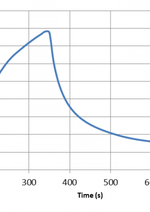
For designs where the plant rooms are directly connected to the lobby, the extract points are located in the plant rooms. An analysis was carried out to a typical plant room with dimension of 6m x 5m x 3m by using CFAST [4] modelling. The plant room is assumed to be enclosed with brick walls and the fire door is kept closed. A fire with medium t-squared growth rate is assumed. Figure 1 below shows the temperature distribution in the plant room.
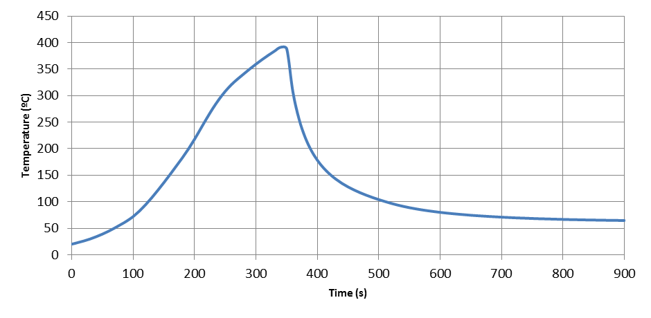
Figure 1: Temperature of hot smoke in the plant room
The analysis indicates that the maximum hot smoke temperature in the plant room is approximately 380ºC; however, the period of smoke temperature over 300ºC is less than two minutes. Considering the heat loss in the duct, the smoke temperature will be even lower when it reaches the fan. Hence, fan rating of 300oC is considered suitable for use as the design of the fan will take care of short durations of over temperature. Furthermore, a duty and standby fan assembly has been included in the design. If the fan fails due to the short duration of over temperature, the standby fan will start to operate. The hot smoke temperature will quickly drop down to below 300oC. The standby fan will not be subject to over temperature and will be kept functional for the rest of the time period required in BS EN 12101-6. Therefore, the functional requirement of the pressurization system will be satisfied. A sensitivity analysis was carried on hot smoke temperature in relation to the size of room. The result indicates that changes to hot smoke temperature are small with an increase or decrease in size of room.
Interface Design
Figure 2 illustrates how the pressurisation system is interconnected to the air release control and the remote control and monitoring systems, namely BMS (Building Management System) and SCADA. The Figure provides a description of the functional blocks that control the operation of the stair pressurisation /air release system within Stations, Shafts and Portals. It highlights the key interface parties, where the interfaces take place and key interface information transfer that will permit co-ordinated performance of the system as a whole.
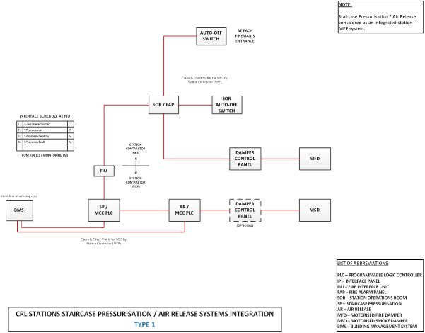
Figure 2: Interface Schematic for a typical stair pressurisation and air release system
Technical Assurance
Table 1 below sets out the technical assurance requirements in respect of the inspection, commissioning test plan for the fire fighting stair pressurisation and air release system. The intent of the assurance scheme is to verify that the stair pressurisation system is fully functional, compliant with the performance requirement stipulated in BS EN 12101-6 Class B and fully integrated with other station systems.
Table 1: Technical Assurance Requirement for Inspection and Commissioning of Stair Pressurisation System
System Overview Equipment list of stair pressurization system c/w related test report Equipment list of builder’s work (such as doorset, door closer & etc.) c/w related test report Certification that the building air tightness condition during the testing is equivalent to the occupation condition System Description Designation of pressurized staircase Pressurized space: Escape staircase, Fire fighting staircase Equipment provided (Duplicate fans in series, duplicate fans in parallel) Design air velocity passes through the door between pressurized space and accommodation area Design differential pressure between the pressurized space and accommodation Design door opening force Test report Pressure test report of all ductwork (including builder’s work, ducts, shafts or plenum) Air velocity measurement report Door opening force measurement report Differential pressure measurement report System performance test report Pre-commissioning Air intake- for air intake not located at roof Position of air intake is located away from any potential fire hazards (such as basement smoke vent) Air duct is provided from the intake to the fan when air intake is distant from the fan A smoke detector of a type suitable for use in air duct / plenum is installed Pressurization system can be shut down when the duct type smoke detector is activated Air intake- for air intake located at roof There are two air intakes, which are spaced apart and facing different directions Each intake is capable of providing the full air requirements of the system. Independently operated smoke control damper with duct type smoke detector is provided at each intake An override switch to reopen the closed damper and to close the open damper is provided No smoke discharge within 5 m of any direction of air intake Air duct is provided from the intake to the fan when air intake is distant from the fan Smoke control damper properly actuated when duct type smoke detector activated Plant room List other un-related engineering systems inside the plant room Minimum fire resistance rating for the enclosure of the pressurization plant is equal to or greater than the pressurized space served When the plant room houses equipment for more than one pressurization system, separate fire rated enclosure is provided to each pressurization system in order to maintain fire compartmentation between different pressurized spaces When fan room is used as an air plenum, all control panels should be located outside the fan room, or protected by fire resistant enclosure(s) Air injection point & associated ductwork Volume control dampers of air injection points are properly secured Injection duct work passing through other fire compartment is constructed to have the same Fire Resistance Rating (FRR) required for either the pressurized space or the compartment through it passes, whichever is the greater Ductwork construction is complied with or not less than DW144 [5] standard Air release Spread of smoke between different fire compartments does not happen in both normal operation and fail safe mode When the operation of air release system is automatic, it is actuated by the same detector / device that actuates the rest of the pressurization system Air release vent is located at or immediately below ceiling level When the central exhaust system also serves for mechanical air release, component & ductwork of central exhaust system is capable of working at the appropriate temperature and period of time; The local motorized smoke damper in fire floor is opened and dampers for other compartments / units are closed Over pressure relief Wire mesh is provided at the external opening of relief vent / damper Relief vent / duct passed through other fire compartment is enclosed by fire rated material; the FRR should be same of pressurized space or the compartment through it passes, whichever is greater Electrical & control Electrical supplies for all equipment (such as fans, air relief damper, over pressure device, controller, supervisory panel & etc.) are fed from the same electricity supply source Separate pressure differential system is provided for each pressurized system End of pressure sensing tube is properly terminated at the pressurized space and accommodation End of sensing tube is mechanically protected Label of “Sensing point of stair pressurization system” is clearly indicated Protection is provided along the sensing tube Power supplies for the differential pressure sensor, control, over pressure device, air release device are distributed from sub-circuit of stair pressurization system Manual override switch provided on local fan control panel is locked in “Automatic control” position An indication signal is transmitted to supervisory control panel, when local fan control panel is in manual control mode Functional tests Performance test is carried out and the result is satisfactory Measurement of door opening force is carried out and result is satisfactory Measurement of differential pressure across the pressurized space and accommodation is carried out and the result is satisfactory Measurement of pressurized air flow is carried out and the result is satisfactory Air intake fire/smoke damper is closed when the duct type smoke detector is activated; or Stair pressurization system is shut down when the duct smoke detector at air intake is activated In order to prevent over pressure in pressurized space, fail safe protection for over pressure release is provided on conditions of :-
· Failure of controller.
· Failure of pressure switch.
· Failure of wiring of pressure switch.
· Failure of actuator of by-pass damper.
· Failure of wiring of actuator (by-pass damper)
Functional test of actuation by fire alarm panel and from remote via SCADA (for shafts and portals only)- simulated test from interface panel Functional test of firefighter auto- off override switch Functional test of response time- The system is capable of achieving between 90% & 110% of the new volumetric requirements within 5 sec of a door being opened or closed (for the over pressure release system by using variable supply fans or dampers) Changeover from the duty equipment to the standby equipment is automatically operated when failure occurred in duty equipment Compliance Tests as per tests as required in Technical Assurance Requirements for the Testing &Commissioning of Mechanical Electrical and Public Health Installations at Stations, Shafts and Portals Static Integration Tests Operation of pressurisation system when Tunnel Ventilation System (TVS) is in operation- Door opening force, Opening of firefighting lift door, Minimum velocity through the open stair door, Static pressure differentials between staircase/ lobbies and protected routes Verify that firefighting lift doors will operate normally under fluctuations in air pressure under train piston effect and while TVS/ pressurisation system is in operation Demonstrate RCC can activate the shaft pressure ventilation (fire-fighting lifts and stairways) during emergency situation (end to end test) Operation Readiness Tests Demonstrate compliance with operation requirements prior to system handover References
[1] BS 9999:2008, Code of practice for fire safety in the design, management and use of buildings, BSI, 2008
[2] BS EN12101-6:2005, Smoke and heat control systems – Part 6: Specification for pressure differential systems – Kits, BSI, 2006
[3] BS EN 12101-8:2011 Smoke and heat control systems – Part 8: Smoke control dampers, BSI, 2011
[4] CFAST, Consolidated Model of Fire and Smoke Transport, NIST
[5] DW/l44, Specification for Sheet Metal Ductwork Low, medium and high pressure/velocity air systems, Heating and Ventilating Contractors’ Association, 1998
-
Authors

Wing Fung PhD MSc BSc(Eng) CEng MCIBSE - Arcadis
Technical Director (MEP), Arcadis
Wing is is a Chartered Engineer with over 30 years’ experience as a technical specialist engaged in mass transit system planning, design, project management, technical assurance, commissioning, energy management, operation and maintenance, and asset renewal. Wing has been with the Crossrail project in the CRL Chief Engineer Group since 2013, overseeing mechanical design, systems integration and T&C.
Specialties: Building Services, Mechanical Engineering, Computational Fluid Dynamics, RAM studies, Systems Integration, Requirement Management, Testing and Commissioning.
