Base Grouting, Osterberg Cell Test and the use of Fibre Optics in large diameter rotary bored piles
Document
type: Technical Paper
Author:
Kirstie Broadbent
Publication
Date: 10/11/2015
-
Read the full document
1. INTRODUCTION
The site is situated east of London, approximately 700m north of the River Thames. The ground conditions comprised London Clay over Lambeth Clay becoming Lambeth Sand over Thanet Sands into which the piles were founded. Due to the extensive, existing and proposed, underground network of infrastructure within London, the use of permanent liners to bearing piles are increasingly required to prevent any impact on these tunnels due to the increasing possibility of surcharge loads. As demolished structures are replaced with higher rise buildings, piled foundation demand, and the loads to be resisted, has increased.
Due to high capacity of the Thanet Sands, both in shaft and end bearing, it optimises design if these heavily loaded piles found within this strata. As the Thanet Sand is often limited in thickness, underlain by weaker, less reliable strata, such as chalk, the length of pile can be restricted to get the optimum efficiency of capacity which leads to greater reliance on the end bearing resistance.
In order to mobilise the end bearing the pile must settle. The level of settlement generally exceeds the allowable structural design requirements. Standard pile design for piles founding in the Thanet Sand is to adopt a factor of safety (FoS) of greater than 1.1 times the Safe Working Load (SWL) on the shaft capacity alone. Where the Thanet sand thickness is limited and liners are used this can be difficult to achieve if the loads are high. The settlement when mobilising end bearing is directly affected by the cleanliness of the base. Predictive settlement calculation in designs use the soils elastic modulus which is generally derived from the Standard Penetration Test (SPT) ‘N’ value. Thanet sand is a fine and almost single size marine silty sand, which has a high relative density indicated by the SPT ‘N’ value in excess of 100 for 300 mm penetration. It is standard practice to cap the ‘N’ value when defining the elastic modulus. In these circumstances, as at Farringdon, Base Grouting is often considered a viable option to ensure a higher elastic modulus of the base and incorporating it into the design to reduce settlement and take the loads.
The piles were excavated as 2.4m diameter piles to the liner toe for installation of the dual sleeves. Below the toe of the liners, the 2.1m diameter pile was excavated, using support fluid once outside the clay. Once toe level is reached and the base cleaned, reinforcement was placed and the pile concreted. 4No. base grouting Tube-A-Manchette (TAM) circuits and two extensometer tubes were fabricated into the reinforcement cages, enabling grouting of the base, post installation.
2. BASE GROUTING
Background reading highlighted two contradictory theories of the benefits of base grouting. Theory A, (Fleming, 1993), suggests uplift negatively loads the soil, increasing pile shaft capacity as well as improving end bearing while still noting no overall increase in capacity in the ground. Theory B, (Troughton & Stocker, 1996) suggests base grouting reduces settlement, and allows lowering Factors of Safety (FoS) on shaft, through permitting greater inclusion of end bearing into the pile design.
The current Industry Specification, commonly referenced for base grouting, is the Institution of Civil Engineers Specification for Piling and Embedded Retaining Walls (ICE SPERW) which defines uplift as the key demonstration of successful base grouting with a prescription of no less than 0.2mm and no greater than 2mm under clause B3.5.11.4.
The guidance notes within this specification under clause C3.5.11.2 highlight that uplift may not occur if the pile is long and thin. However, there is no reference as to what ratio of diameter to length can be defined as ‘thin’ in order to advise practitioners of the discipline or Designers wishing to incorporate the discipline into their design.
A predicted upwards movement was calculated using in-house theoretical design software, Bearing v1.1.1 to determine shaft capacity and CEMset v4.01 for the settlement, based on parameters from information within the Geotechnical Baseline Report (GBR) and relevant boreholes, taking end bearing as zero and likely parameters and appropriate factors of safety as in standard design practice. The upwards force was initially calculated, assuming 100% contact of constant maximum achievable pressure (assuming equal loss of system pressure and increased head pressure for simplification), with the self-weight force deducted. Initial calculations suggested 3.4mm uplift could be expected, in line with ICE SPERW.
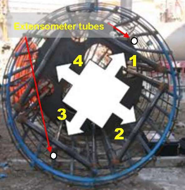
Figure 1: Base Grouting Circuit Arrangement
4No. base grouting Tube-A-Manchette (T-A-M) circuits and two extensometer tubes were fabricated within the reinforcement cages to allow the grouting (Figure 1). The day after pile construction, while the concrete strength is low, the seal in the T-A-Ms is broken by pumping water under pressure. The pressure is monitored and the T-A-M seal is considered cracked once pressure drops. After a minimum of 3 days of concrete curing, the piles were base grouted. Optical Fibre Sensors (OFS) were installed the length of the pile along the edge of the cage in the working test pile. The instrumented test pile’s performance under grouting was captured by OFS at different locations around the circumference of the pile, however, the details of these results will be captured in another paper. At Farringdon, four grouting circuits were used (As shown in Figure 1). In this case the conventional sequence is to grout circuit 1, followed by 3, then 2, then 4 (i.e. opposite sides of pile). The use of 4 circuits should be reviewed on the basis of the pile diameter and project specification. Should the criteria for grouting not be achieved within the first phase of grouting then it is repeated. Standard practice is to limit the number of phases to 3 as little or no grout is able to be injected past this point.
By reflecting on practicalities of procedure, steady reductions of injected volume and quicker pressure cut offs after each circuit were noticed. This suggested disturbed soil voids were being filled from initial circuits, reducing area available for grout to flow and possibly lesser contact area than originally assumed for the final phase. From recalculation the expected uplift was 0.4mm. In addition, based on theory B, the purpose is to permit less conservative SPT values to be incorporated into the design to permit a greater elastic modulus of the soil at the base in order to reduce the settlement necessary to mobilise the base resistance. It should therefore be considered that other criteria can be used to determine whether the actual outcome is achieved.
More recent research of base grouting uncovers the Arup Ranking method (Patel et al, 2009), differing from ICE SPERW. This method was proposed, yet it was initially rejected at C435 due to limited use within the industry and uplift being deemed the only way to demonstrate sufficient cleanliness of the base to confirm design assumptions. However, as uplift was consistently not achieved, CSL followed the procedure for this method as a second check. The method requires monitoring of several parameters as follows:
- Base condition prior to concreting
- Total Volume of Grout injected
- Maximum Pressure
- Residual Pressure
- Uplift
These items are reviewed against a set of criteria as detailed in Patel D et al, 2009. Each item is assigned a score in accordance with the method, based on the output result. The final score is totalled and provided the overall score is greater than 7 the base grouting is deemed acceptable.
With the load test confirming greater than expected shaft resistance it is considered that minimal uplift may not mean poor base grouting but rather greater shaft capacity or simply too high a shaft resistance to permit movement. As a result, going forward on future projects with base grouting, a more all-encompassing set of criteria similarly to the aforementioned ranking method may be a more suitable approach for inclusion in inspection and testing.
3. OSTERBERG CELL TEST
The key differences between the Osterberg Cell Test (O Cell) and a standard static load test are:
1. Bi-directional loading, permitting separate assessment of shaft from end bearing resistance and;
2. Maximum test load.
3. Potential re-use of the load cell permitting stopping and restarting of the test.
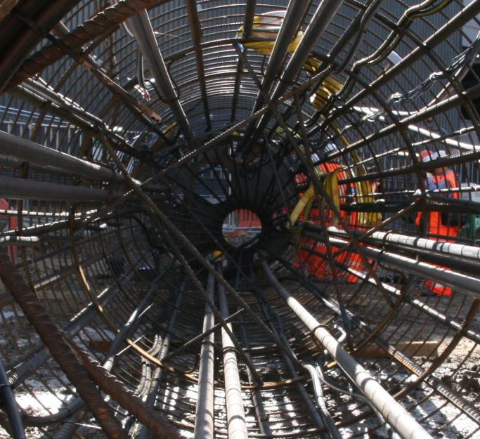
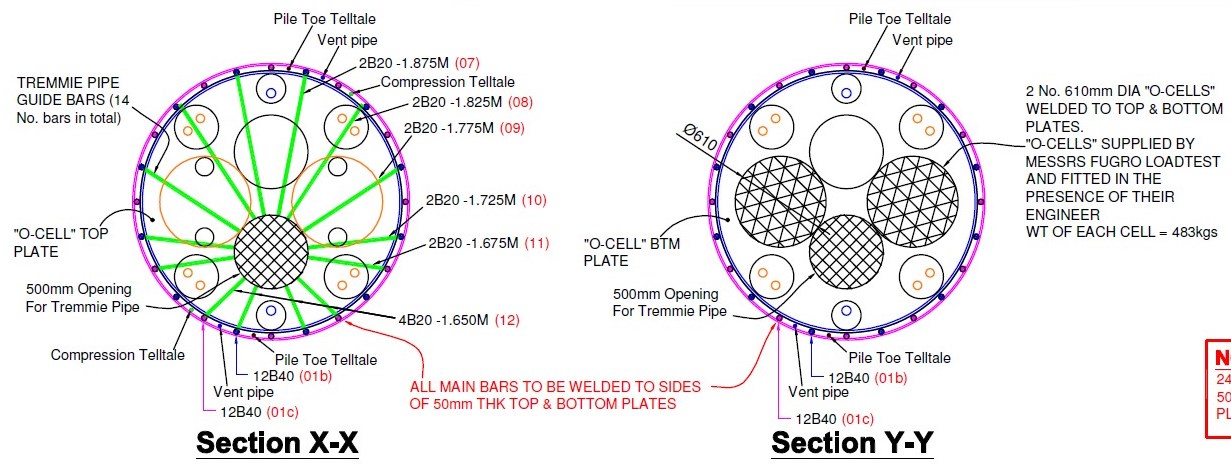
Figure 2: Osterberg Cell Plate/Tremmie Guide from top
The preparation for this test mainly lies with offsite works. The Osterberg Cell is only produced overseas and therefore currently needs to be imported. The cell is welded into position into the reinforcement cage. The position of the cell(s) needs to be such that it permits a tremmie pipe (Figure 2 & Figure 3) to enter through the plate for concreting both in wet and dry installation conditions to allow for the event of water ingress.
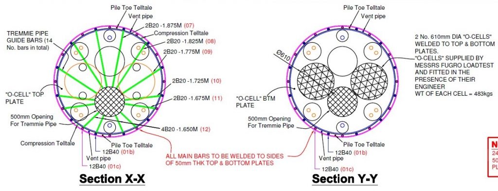
Figure 3: Osterberg Cell Fabrication Drawing
In addition the plates between which the cell is welded need to permit the flow of concrete. To prevent air build up, which may affect results, during testing, there also vent pipes installed. Furthermore, there are tell-tale bars to permit measurement of the cell expansion and the movement in both the downwards and upwards directions separately (Figure 3). In addition to this, as with base grouting reference beams and dial gauges are also used at the top of the pile to determine uplift. The base supports for these beams were 12m apart to ensure the surrounding ground was not moving with the pile and affecting the readings.
All tubes and reinforcement bars within the working test pile were scored and cut, respectively, once the cage was fabricated. This is to prevent the steel from adding to the resistance capacity in preventing the expansion of the cell and affecting the results. The tubes are scored to a depth that will still permit their use during base grouting and sonic logging. The plate is held together by reinforcement bars in the temporary condition to permit lifting. Once in the vertical position over the pile the bars are cut (Figure 4) and the bottom of the cage is held in place through the welds on the cells connecting them.
The test requires less site area and the majority of preparation can be carried out off site, with no need for anchor piles. Restraint at the top would prevent differentiation between resistance from the shaft or anchors and the test would only, also less effectively, determine capacity of the end bearing, leaving the test possibly ineffective in confirming design assumptions.
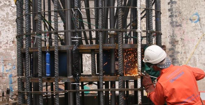
Figure 4: Temporary works bars for lifting being cut
However, with no anchor piles the ability to test the base to the full extent of the desire load requires sufficient shaft capacity of the pile above the cell to the shaft and base below. Throughout the test, movement is monitored, as with standard tests. It can be stopped at any time should the overall movement or the rate exceed the desired amount. As a result, less conservative design assumptions could be adopted that may be different to the permanent works design when determining the anchor resistance.
At Farringdon the design suggested the shaft capacity was not sufficient to resist the full test load to verify the base resistance. CSL’s in-house design team drew similar conclusions from a preliminary review of the relevant soil information. Fugro Loadtest, who were contracted to carry out the specialist test, suggested the design assumptions were conservative based on similar tests in the area. Through close liaison between contractor and consulting engineer, the loading cycle was altered from the ICE SPERW and approved through normal process. Acceptable movement limits at each stage were also agreed. If, at any point, limits were exceeded or unexpected the test would be stopped and if insufficient data was recovered, an alternative means of restraint would be installed for retesting.
Therefore the greatest lesson from the Osterberg cell test at Farringdon is that the shaft resistance above the cell should be considered when determining which pile should be designated as the test pile. This is to ensure there is sufficient capacity. Furthermore, it should be a fully collaborative part of any scheme with clear communication and understanding of expectations from all parties including the specialist test house, piling installation contractor as well as the consulting engineer and main contractor.
It is also worth noting that the Osterberg cell test could possibly be re-used and therefore it should be considered whether, within the industry, going forward we should be considering their installation for ongoing monitoring of as-built pile capacity over time and whether this may permit increased pile re-use as cities like London become more and more developed.
4. FIBRE OPTICS & STRAIN GAUGES
In collaboration with the University of Cambridge Centre for Smart Infrastructure and Construction (CSIC), and in support of research using innovative instrumentation, CSL installed fibre optics, as an alternative strain measurement method, to the strain gauges permitting secondary analysis and research. The detail of this has been published within the proceedings of the Edinburgh conference “The use of fibre optic instrumentation to monitor the OCell load test on a single working pile in London”. Within this paper the focus is on the practicalities of their use and site considerations.
Conventional wire strain gauges can be installed completely off site with designed in junctions at the splice for connection during cage placement. Once fully connected, the data can be fed into the analyser. The limitation is that the data received is at discreet points dependant on the placement of the reinforcement cage to ensure the right level of the data capture desired. Should excavation reveal different ground conditions, resulting in a change in level for data capture, the gauges will need to be moved on site prior to installing the cage.
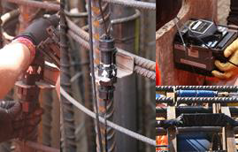
Figure 5: Fibre Optic Strain Cable Installation & Repair
The fibre optics can be installed partly off site by installing them within the base section of cage. However, they can as easily be installed on site completely. Provided the cage is delivered with enough time before placing the reinforcement this will have no impact on programme. There needs to be allowance within both the temperature and strain fibre optic sensor cable, at the cells location, to permit expansion without damage to the cable if using them to monitor a bi-directional load cell test. The Cable must be continuous, which requires careful installation. Repairs can be carried out on site if there are breakages.
The strain cable is fixed into tension at the top and bottom of each cage section to permit continuous analysis between these points. Once the sensor cables are installed in the base cage section the remaining sections will be installed as the cage is lowered into position. This will add a little amount of time onto the reinforcement cage installation period which should be considered in any programming of the works. This should be reviewed against the number of cables being installed and the number of cage sections the cable is to be spread across.
The main advantage of fibre optic technology is the continuous strain results that allow a more detailed analysis of the ground and its capacity along the full length of the pile. As this method of analysis can be connected to at any point in the future, this data could be captured after installation for the as-built and loaded conditions as well as for test piles, if the cables remain exposed for connection to the analyser. Going forward this would be of benefit to be used to provide long term benefits. Furthermore, If combined with an Osterberg Cell this really could be an opportunity for true Smartpiles™ with the possibility of increased long term sustainability and re-use of piles through re-testing of piles.
5. TWIN WALLED LINERS
Twin walled Liners are commonly used in London, due to the high amount of existing tunnels, as a method of preventing transfer of surcharge load that may cause damage or affect the tunnels behaviour. At Farringdon, the sequencing meant the tunnels were installed after the piles and it was understood the liners were a method to prevent the tunnels loading the piles both during the tunnel construction and use and causing additional loading which they won’t have been designed for.

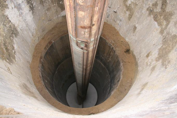
Figure 6: Excavation of Sand after grouting annulus.
At Farringdon, twin walled liners were used with bitumen coating on the inner liner. The purpose of the bitumen is to create a smooth surface with a reduced transfer of friction. The ground within the UK is generally at a temperature between 8-10ºC and once the bitumen temperature rises the bitumen becomes less brittle and more fluid theoretically permitting the piles behaviour to be separate from the surrounding ground. The use of two liners and grouting within the annulus between the inner and outer prevents the temporary casing from being grouted into place.
There is often significant wastage of steel when installing permanent liners as to permit installation they are often carried up to the top of casing level. At Farringdon, to reduce cost and material wastage a method was devised to permit lowering the top level of the liners to COL. This was done by installing two hollow circular lifting points on opposite points of the cylinders. Using quick release shackles in reverse we were able to lower the liners into replace and then disconnect the lifting accessory with ease.
However, there is limitation in achievable tolerances of positioning and verticality. At Farringdon tolerances were increased through the Field Change Document request process. This change altered verticality to 1:100. The original specification verticality of 1:200 was problematic for the method of installation due to the large amount of made ground and the size of piles.
To prevent buckling of the liners, due to hydrostatic pressures of grouting the annulus, the inner liner was filled with sand to at least one meter below the grout level (Figure 6). This needs to be allowed for in the programming durations. The use of sand as opposed to backfill material was selected to ensure even compaction of a consistent material. The grout needs to cure before the sand can be removed and the pile completed. As a result the key lesson is timing of grouting the annulus within the first shift being critical to programme as delaying it to a following shift can add on a further shift to the programme. This is therefore a lesson in the importance of transparency in installation processes as well as realistic tolerance conditions for placement of liners.
6. SUMMARY
Based on near zero movement of the piles and guidance notes within the ICE SPERW it is concluded that the criteria of uplift may be based on ground conditions that don’t reflect the factors of safety that are introduced into the design and thus this may not be key to determining satisfactory base grouting. Due to improvements of instrumentation and monitoring the recorded uplift is now measured and recorded by automatic digital gauges with an increased degree of accuracy. An all-encompassing assessment of the pressure, volume and uplift such as the Arup Ranking method (Patel et al 2009) allows parameters other than uplift to demonstrate success in order to provide assurance, based on more than one set of criteria that the grouting has been carried out correctly. This method could be site specific with criteria being adapted to suit ground conditions, pile sizes and lengths to determine likely uplifts and volumes and pressures.
Upon completion of the O-cell test, it was possible to reassess the movement against the known strata, which confirmed the original design capacity assumptions were conservative. Combining this realisation with minimal base movement, a ranking method such as Arup’s is proposed to be adopted as standard practice going forward.
Based on the experience of base grouting within the scope of this project, and the limited as well as contradictory information available, it would benefit the industry and its’ clients to invest in further research into the use of this discipline to determine the benefits and cost effectiveness of the solution.
The Osterberg Cell Test is a simple test with preparation predominantly carried out off site. There is no need for additional anchors, however there needs to be design checks to confirm shaft resistance above the cell is greater than the proposed load to be tested below. More than one cell can be used to achieve larger loads and they can be positioned to permit concrete flow and tremmie access. There is some additional time required on site to allow the bars to be cut and the top plate greased for de-bonding to permit the cell to expand freely. For the additional checking of the cage – additional space is required to lay both sections of cage down unless it is possible to do the checking off site which can be client dependant. The ability to re-use the cell was not taken advantage on the C435 contract. However, this additional benefit could create the opportunity to re-test piles It could be the future of the foundation industry to combine such load cell tests and their capacity for re-use with the fibre optics to create the ability to re-test piles to determine their capacity for re-use in the future when the building may have changed hands with an alteration to use and/or loading to reduce the life cycle costing of the building.
The use of fibre optics for strain analysis of the pile gave the soil strength profile along the entire shaft length of the pile. The cables are easily installed and can be done on site with minimal impact to piling works. Some consideration should be made for space needed to lay the cage down if they are to be installed on site. Using strain gauges relies on the cage to be installed in position and for the gauges themselves to be in the correct position requiring additional onsite checks to be carried out. This method of analysis has many benefits and could allow us to monitor the pile and ground behaviour over time if the cables can be connected to at a later date.
The installation of liners can be done with ease however, the positioning and achievable verticality should be reviewed on a project by project basis considering the liner length, level below top of casing, ground conditions as well as placement method. When using twin walled grouted liners the programme durations need to consider the need for placing a homogenous material within the liners to prevent buckling under the hydrostatic pressure of the grout. In addition, the sequence of work and how delays to individual activities can affect the overall programme should be considered and identified with a transparent programme. The use of quick release shackles in reverse permitted the liners to be placed at cut off level rather than being brought to the surface. This made a great saving of steel. However, this was only possible as a temporary casing was also used to support the ground above. In addition, using dual liners meant the grout was within the annulus and the temporary casing did not become grouted into position.
7. REFERENCES
Fleming W.G.K, May 1993, Paper 3078, Proceedings of the institution of Civil Engineers, pages 88-93, ‘The improvement of pile performance by Base Grouting’.
Institution of Civil Engineers (ICE), 2007, ICE Specification for Piling and Embedded Retaining Walls, Second Edition.
Ouyang Y et al, 2015, Proceedings of the 16th European Conference on Soil Mechanics and Geotechnical Engineering, ‘The use of fibre optic instrumentation to monitor the O-Cell load test on a single working pile in London’
Patel D, Glover S, Chew J, Austin J, Ove Arup & Partners, ‘The Pinnacle – Design & Construction of Large Diameter Deep Base Grouted Piles in London, 2009
Troughton V M, Stocker M, July 1996, Issue 119, Proceedings of the institution of Civil Engineers, pages 186-192 ‘Base and Shaft Grouted Piles’.
-
Authors