Behaviour of a thermal wall installed in the Tottenham Court Road station box
Document
type: Technical Paper
Author:
Kenichi Soga, Rui Yi, Duncan P Nicholson BSc MSc DIC CEng MICE
Publication
Date: 10/11/2015
-
Read the full document
1 Introduction
Ground source heat pump (GSHP) system is a technology that can provide heating and cooling to buildings and infrastructures with geothermal energy. The ground is used as a heat source for heating or a sink for cooling and the balance of the two can keep the average ground temperature to be constant for reliable long-term operation. A typical GSHP system used in urban settings consists of a closed pipe system buried in the ground and filled with thermal transfer fluid. When the fluid travels around the pipe loops, it absorbs heat from, or gives heat out to the ground. Experiences have shown that a GSHP system has the potential to save up to two thirds of conventional heating costs.
For new building and infrastructure developments, one way of reducing this cost is to install the ground source heat pump system through the foundation elements such as piles and diaphragm walls. Such “geothermal underground infrastructure” functions not only to carry a building’s mechanical load but also as a heat exchanger. This geothermal underground infrastructure approach is considered as potentially cost-effective due to small additional installation cost and less occupied land/underground space.
There have been many studies into thermal piles, but limited research has been performed on thermal walls. Brandl (2006) described heat transfer in the ground, and between the absorber fluid and the concrete/soil. Temperature-induced changes in soil properties or of the thermal pile/thermal wall behaviour were also discussed, and recommendations for design and operation were given. In Brandl’s case, geothermal loops were installed in the U2/2-Taborstraße metro station in Vienna, Austria. This success encouraged the Vienna Underground, which further used GSHP coupled foundations in several station refurbishments. Amis (2009) described the installation of a thermal wall at the Bulgari Hotel in London, and discussed the potential effects of thermal changes during operation. It was found that, once operational, daily loop temperature fluctuations will be considerably less than those of exposed concrete during a winter’s day.
With the operation of GSHP in a wall, the cyclic thermal loadings would affect the structural performance of the wall. During winter cycle (soil cooling), the soil skeleton and the pore fluid contract. Because the thermal expansion coefficient of water is greater than that of the soil skeleton, the pore pressure decreases in undrained conditions, and the total stress acting on the wall may change as a result. During summer cycle (soil warming), the soil is heated, so the opposite trend is expected. The soil skeleton and the pore fluid expand but in different degrees, increasing the pore pressure in undrained conditions. The total stress acting on the wall may again change. More importantly the
temperature difference across the wall would induce thermal strain variations within the concrete structure, resulting in an increase in the curvature and hence bending moments. The magnitude of such thermal effects on the mechanical performance of the wall needs to be examined.2 Tottenham Court Road station box
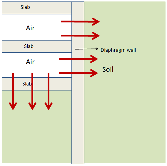
Tottenham Court Road station box is situated at the intersection of Tottenham Court Road and Oxford Street. The thermal walls were constructed using the ‘bottom up’ method. A 1 m diaphragm wall (up to 40 m depth) was first installed by excavating a trench to the required depth, as shown in Figure 1a. The absorber pipes were attached to the reinforcement cage and lowered into the trench. The position of the pipes within the concrete is usually close to the soil side (see Figure 1b), which can reduce the thermal resistance of the concrete and improve the overall thermal performance of the thermal wall. Concrete was then poured in to cast the diaphragm wall. The soil inside the diaphragm box was excavated 25 m deep and temporary props were added to support the excavation. Slabs were cast from the bottom and work proceeded upwards, replacing the props with slabs to form the station box using five levels.
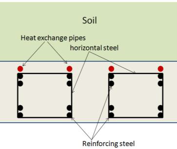
(a) Thermal wall (b) Geometry of thermal wall
Figure 1 – Thermal walls installed in Tottenham Court Road station box
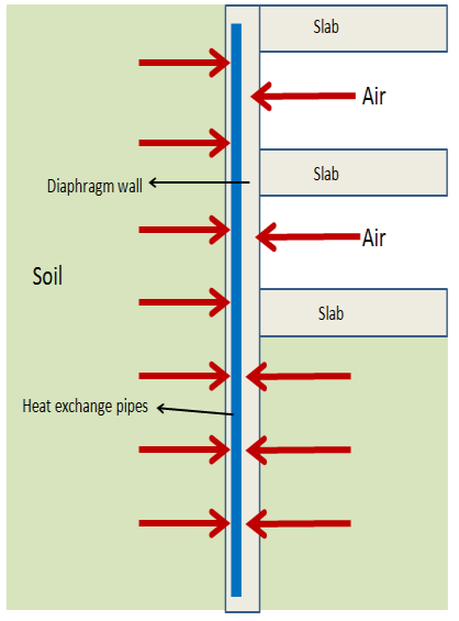
Winter Summer Figure 2 – Possible GSHP operating mode for underground station
There are two possible GSHP operating modes for station boxes: (a) both heating and cooling, and (b) heating only (Figure 2). If a thermal wall is used for basement, then the interior side of the wall is insulated to ensure that the heat from the exchangers transfers into the soil rather than into the basement. By doing so, it can cater for both heating and cooling of the aboveground structures. For underground railway stations, there is a possibility to extract heat in winter time from both sides of the wall (station and soil) because stations often have excessive heat generated by train operations. In summer time, the GSHPs are not used and the excessive heat from the station is transferred into the soil. The heat stored in summer then can be used in winter for heating the aboveground structures. The latter case is considered in this study.
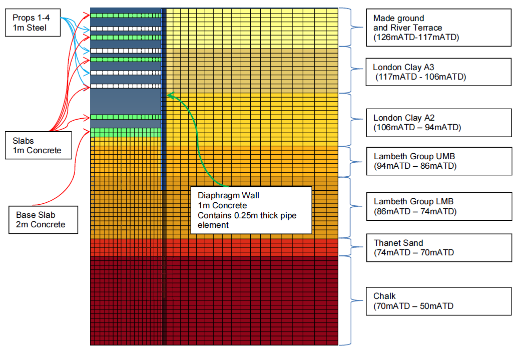
3 Thermo-hydro-mechanical behaviour of the station box
For the purpose of analysing the THM response, the station box was simplified into a 2D model to save computation time. By assuming the box is symmetrical, only half of the box was modelled as shown in Figure 1a. The top soil is 9 m of made ground and river terrace, underlain by 23 m thick stiff London clay. Below this are mixed soil layers of clay, silt and sand, called the Lambeth group. The thermo-mechanical behaviour of the soils were modelled using a non-linear stiffness gradation model with Mohr-Coulomb yield criterion. The thermal expansion behaviour of soil skeleton and pore fluid was also included in the model. The model parameters followed the values recommended for the Crossrail design. Further details of the model can be found in Rui (2015).
The box side is 16m wide and 29m deep. The diaphragm wall is 1m wide and 41m deep. In the FE model, the soil is 76m deep and extends for 80m laterally from the wall. It has four temporary props (white) and six slabs and one slab is a direct replacement of a temporary prop that was included in the original design. The absorber pipe is placed down to 40m depth, and its centre-centre distance with the wall is 0.25m towards the soil side. The bottom 1m of the wall does not have pipes.
The scope of this project involved the analysis of the seasonal operation effects of a thermal wall on the structural performance of the wall. The analysis was split into two phases; (a) the Construction Phase (Hydro-Mechanical Response) – to calibrate the governing model parameters for soil behaviour using the displacement data obtained during the construction of the wall, and (b) the Operation Phase (Thermo-Hydro-Mechanical Response) – to analyse the complex THM interactions between the soil and diaphragm wall during heating and cooling cycles in order to assess the structural response of the wall by GSHP operation. To deduce whether the THM response in the soil would affect the wall performance, the earth pressure and ground deformation in the soil and the bending moment and displacement of the wall were computed. The FE numerical simulation of the model was performed using a FE code developing at Cambridge University Engineering Department for solving fully coupled THM problems (Rui, 2015).
Construction stage
For the simulation of the construction processes, the lateral pressure ratio K0 of the soil was set as 1, considering the wall installation effect. In addition, the water table was kept constant at zero pressure at the soil surface for simplicity. The pore pressure distribution was hydrostatic for all elements initially, and the far-field soil boundary was kept hydrostatic throughout. Drainage was allowed at the bottom and the right hand side boundaries for the fluid-soil coupled analysis. In addition, during excavation, drainage was not allowed at the excavation surface. The maximum negative pore pressure within the soil was capped at -100 kPa.
The model was calibrated first with the actual monitoring data to verify whether an appropriate set of stiffness in the soil stratum was selected for the simulation. Figure 3 shows the lateral displacement profile of the wall when the excavation was made to the bottom. The black thick line is the computed displacements, whereas the red thick line is the relative displacement from the bottom of the wall. The thin lines are the measured lateral movements of the wall from the bottom, which were deduced from the readings of the inclinometers placed inside the wall. In general the pattern and magnitude of displacements are similar between the computed results and the measured data, providing some confidence in using the model.
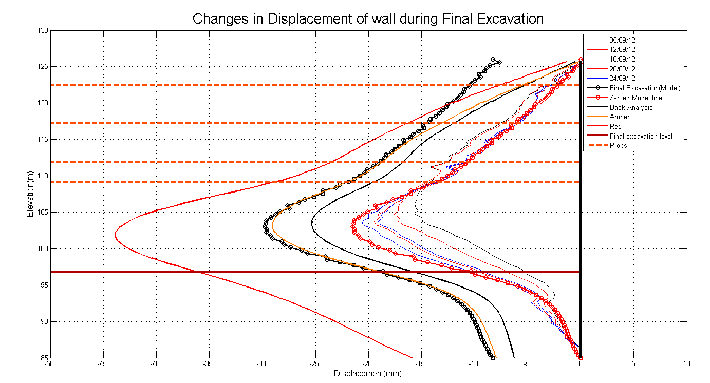
Figure 3 – Lateral displacement profile of the wall after excavation
During the excavation, the horizontal total stresses reduce due to ground movement towards the excavation side, as shown in Figure 4. The largest change occurs when the final excavation takes place. This excavation stage removes ~12m of soil, which is more than twice the amount of soil removed in the second largest excavation (~5 m). The total stress on the soil side reduces to 120 kPa at elevation +103 m. The total stress in the excavation side starts at different elevations due to the removal of soil during excavation.
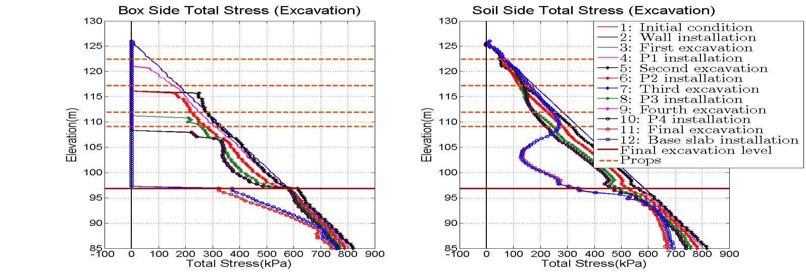
Figure 4 – Profiles of changes in horizontal total stress on the excavation side during excavation (left) and on the soil side during excavation (right).
Figure 5(a) shows the bending moment distributions in the wall at different stages of excavation. The magnitude of bending moment increases as the excavation progresses. The temporary props restrict the movement of the wall as the turning points of the moment curve mostly lie on where the props are. The final excavation has the biggest displacement and curvature at +103m, so the maximum moment is at this elevation as shown in the figure. When the props are replaced with slabs, the moment does not vary greatly, except that the turning points shift from the prop locations to the slab locations. Figure 5(b) shows that the moment envelope after the construction stage (including slab installations) is well within the maximum allowable moment envelope used for the wall design.

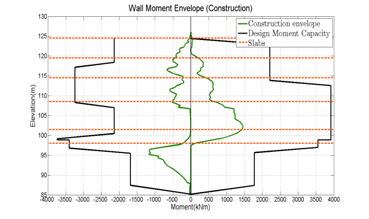
(a) Bending moment profile (b) Bending moment envelope Figure 5 Wall performance during the construction stage
GSHP operation stage
To simulate the 20 year GSHP operation stage, the temperature boundary conditions were varied between winter and summer for 20 cycles. The temperature boundary conditions applied is summarised in Figure 6. The temperatures of the station box and the far-field soil were kept at 18 ˚C and 12 ˚C, respectively at all times. The initial soil temperature was 12 ˚C. The temperature in the pipes were varied between winter and summer cycles; the pipe temperature was set to be 2 ˚C and 18 ˚C for winter and summer, respectively. To quantify the effect of GSHP operation on wall performance, another simulation was conducted by having no GSHP operation for 20 years. In this case, the soil was allowed to swell by the dissipation of the negative excess pore pressure generated during the excavation, so that the long-term “drained” conditions can be achieved.

Figure 6 – Temperature boundary conditions of the thermal wall (Not to scale)
Figure 7 shows the pore pressure profiles at the soil side of the wall for the two cases: with and without GSHP operation). The pore pressures slowly converge to the initial hydrostatic distribution with time. For the case of no GSHP operation (Fig. 7(a)), the negative excess pore pressures developed during the excavation stage dissipate within the first 10 years. If the GSHP system were to be operated, the pore pressures fluctuate seasonally near the wall (Fig. 7(b)). Because the thermal expansion coefficient of water is greater than that of soil skeleton, negative excess pore pressures are generated in winter when the impermeable clay is cooled. This delays the time for the excess pore pressures in the soil to dissipate. The maximum difference in pore pressure between summer and winter cycles is 50kPa at +95m.
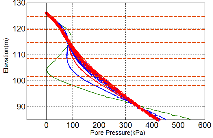
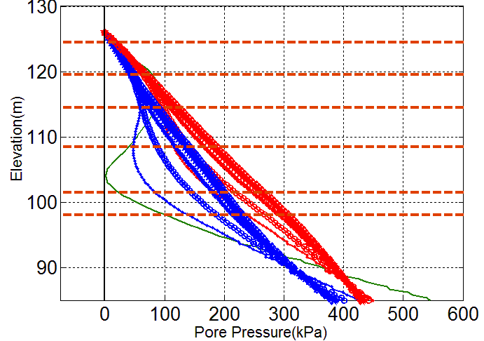
(a) No GHSP operation (b) with GSHP operation Figure 7 – Pore pressure changes at the soil side of the wall
Figure 8 shows the relative horizontal displacement profiles of the wall for the cases (a) without GSHP operation and (b) with GSHP operation. The bottom of the wall is taken as the datum. For the no GSHP case, the horizontal displacements do not vary greatly during the post-construction stage because there is no significant changes in the total stress. The wall gradually shifts to the right with time, which is caused by the dissipation of the excess pore pressures generated during the excavation. The GSHP operation of the wall makes the wall move in a cyclic manner; but the seasonal variation is very small (0.5 mm at the top). In winter, the pipe temperature is cold and the station side of the wall is hot, so this causes thermal strain variations in the wall, causing the wall to bend toward the soil side. In summer, the temperatures of both faces of the wall are similar, bringing back the wall toward the excavation side. Although the magnitude is small, the long-term movement of the wall is toward the soil side. This is due to soil contraction by the permanent cooling observed at locations slightly away from the wall.

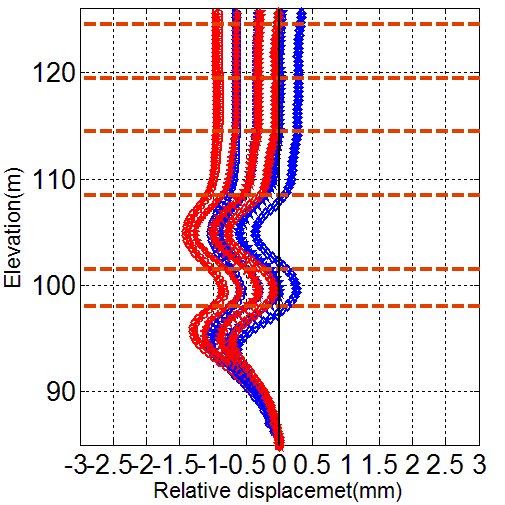
(a) No GHSP operation (b) with GSHP operation Figure 8 Changes in the lateral displacements of the wall
The bending moment in the wall is caused by the lateral stresses from the soil and the slabs and also by the thermal stresses generated by the GSHP operation inside the wall. The pipe circuit is installed near the soil side. During winter, the coolant is 2 ˚C and the far-field soil temperature is 12 ˚C, so the soil side of the wall would shrink. The temperature at the excavation box side is always maintained at 18 ˚C. This temperature gradient inside the wall causes contraction in the soil side of the wall, inducing additional bending moment. However, in summer, the temperature across the wall is more or less uniform, which brings back the bending moment close to the initial condition.
Figure 9 shows the bending moment profiles between winter and summer for (a) no GSHP case and (b) with GSHP case. There is a clear difference in the bending moment between winter and summer cycles. Below the base slab level (+97m), the wall is restrained at both sides by the soil, so the difference between summer and winter cycles is less compared with the portion above +97m where the wall is only restrained by the soil on one side only. There is an offset of about 400kNm between winter and summer at the base slab level.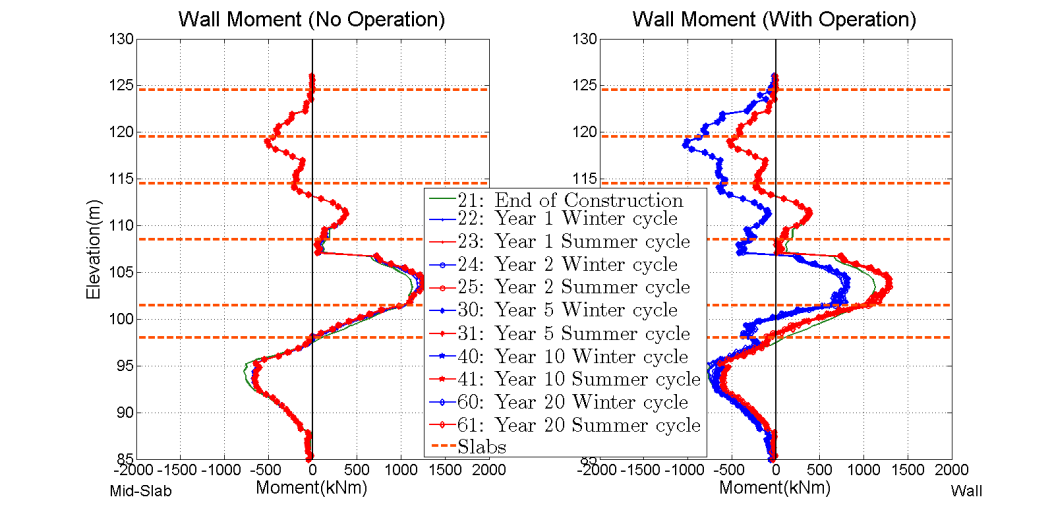
(a) No GSHP operation (b) with GSHP operation
Figure 9 – Changes in the bending moment profile with time
The bending of the wall is primarily due to the thermal gradient within the wall during winter when heat is extracted. Figure 10 shows the bending moment distributions in the wall when simulations were conducted with different thermal expansion coefficient values of concrete. Results show that the change in bending moment is mainly governed by the thermal expansion of the concrete in the wall. In winter, the temperature difference is the largest, resulting in large increase in curvature and therefore moment. The thermal expansion coefficient of concrete is governed the type of binding material (e.g. cement) and aggregates used, which can be part of design consideration of thermal wall. In this case, the thermal expansion and contraction of the soil causes negligible bending moment in the wall. Therefore the thermal expansion of the soil has limited influence on the structural performance during the GSHP operation phase.
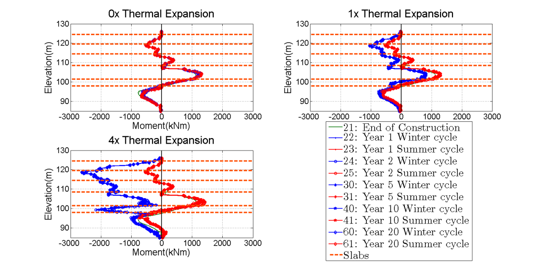
Figure 10 Bending moment profiles with different thermal expansion coefficient of concrete
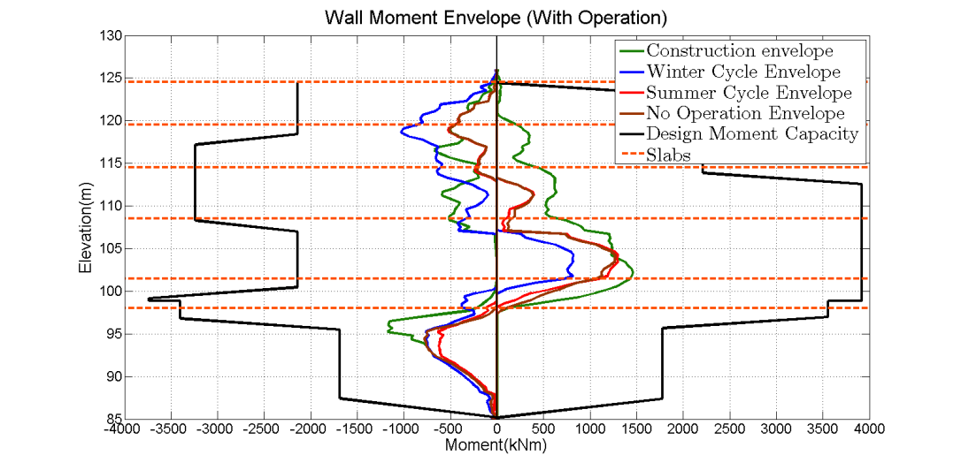
The profile of maximum bending moment in the wall during different stages of the wall is shown in Fig 11. The magnitude of positive bending moment in the GSHP operation stage is lower than in the construction stage because the wall had less lateral supports during the construction stage than after construction where more slabs are added and replaced temporary props. The bending moment predicted using this FE model is well within the maximum design bending moment envelope used in designing of the wall.

Figure 11 Bending moment envelope during GSHP operation
4 Conclusions
With no operation of GSHP, the excess pore pressures developed during the excavation stage returns to almost hydrostatic after 10 years. The wall gradually moves back toward the soil side with time due to swelling of the soil surrounding the wall. With GSHP operation, cold coolant is injected in absorber pipes in winter. Soil shrinks and small changes in earth pressures acting on the wall are observed. In summer, the ground temperature recovers by the heat flux from the station box and the heat is stored for the following winter cycle. Although pore pressure changes are observed due to low permeability of the soil as well as the differences in the thermal expansions of soil and water, the change in total stress acting on the wall appears to be small. Results show that the change in the bending moment of the wall due to seasonal GSHP cycle is mainly caused by the thermal differential across the wall during the winter. This is when the one side of the wall is exposed to the warm station temperature and the other half of the wall at the soil side is cooled by the coolant in the buried pipe. During the 20 year operation of GSHP, a small wall movement (about 1 mm) occurred toward the soil side. This is due to soil shrinkage at a permanent cooling zone located slightly away from the wall. The case study showed that the mechanical performance of thermal wall during GSHP operation requires examination of the effect of (i) concrete expansion differential within the wall, (ii) variations in earth pressures acting on the wall, and (iii) soil shrinkage or expansion due to overall changes in the ground temperature near the wall after many years of GSHP operation.
This paper describes the findings from the analysis investigating the long-term mechanical performance of the station box wall during GSHP operation. The performance of a thermal wall is very much influenced by the heating and cooling inputs from the GSHP system, which depends on the heating and cooling demands of above ground structures. Some discussion on this particular issue is given in Soga et al. (2014).
References
Amis, T. (2009) : “Geothermal business buoyant,” Geodrilling International, (3): 24.
Brandl, H. (2006) : “Energy foundations and other thermo-active ground structures,” Geotechnique, 56(5): 81-122.
Rui, Y. (2015) : Finite Element Modelling of Thermal Piles and Walls, PhD thesis, University of Cambridge
Soga, K., He, Q., Rui, Y. and Nicholson, D. (2014) : “Some considerations for designing GSHP coupled geotechnical structures based on a case study,” The Proceedings of the 7th International Congress on Environmental Geotechnics.
-
Authors

Duncan P Nicholson BSc MSc DIC CEng MICE - Ove Arup and Partners Ltd
Director, Ove Arup and Partners Ltd