C300 Western Running Tunnels and Caverns Project – TBM Shield Burial and Backup Removal
Document
type: Technical Paper
Author:
Anil Dhillon, ICE Publishing
Publication
Date: 07/09/2015
-
Read the full document
Notation
BFK – Bam Ferrovial Kier Joint Venture
EPB – Earth Pressure Balance
ETH – Eastern Ticket Hall
IBC – Intermediate Bulk Container
MPI – Magnetic Particle Inspection
PFA – Pulverised Fuel Ash
SCL – Sprayed Concrete Lining
SLS – Serviceability Limit State
SWL – Safe Working Load
TBM – Tunnel Boring Machine
VE – Value Engineering
WTH – Western Ticket HallIntroduction
Contract C300, the Crossrail Western Running Tunnels and Caverns Project, saw the construction of 6.8 km of twin-bore segmental lined tunnel beneath London from Royal Oak to Farringdon Station (See Figure 1). The contract was awarded in 2011 to a multi-national joint venture between BAM Nuttall, Ferrovial Agroman and Kier Construction (BFK).
The construction of the Western Tunnels commenced with the launch of the two TBMs in mid-2012 culminating in completion of the second drive in late January 2014.
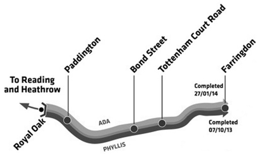
Figure 1 – Western running tunnels overview
Much of the length of the drives saw tunnelling beneath densely populated areas of central London. Advancing eastwards, the drives descended through the London Clay sequence and in to the Lambeth Group before reaching their final destination at the Crossrail Farringdon station. With a combination of soft ground and strict settlement control requirements for tunnelling beneath the urban areas of the Capital, two Earth Pressure Balance (EPB) Tunnel Boring Machines (TBMs) were designed and constructed by Herrenknecht for BFK.
The C300 contract saw significant interfaces at Crossrail’s Bond Street, Tottenham Court Road, and Farringdon stations. Such interfaces required the TBMs to transit through piles, diaphragm walls, as well as shafts or partially constructed Sprayed Concrete Lining (SCL) tunnel works filled with foam concrete.
This paper will initially focus on the interface with the Farringdon station works contract (C435) which led to a significant review of the works programme in order to best sequence the completion of the TBM drives with the ongoing SCL tunnel works in order to identify significant programme opportunities. The paper will then continue to detail the works undertaken in burying the shield, transporting the backup to the Fisher Street ventilation shaft, and finally undertaking the TBM backup removal operation.
TBM Removal
TBM Removal Options
A Value Engineering (VE) proposal was prepared by BFK to compare the original tender/instructed scheme with eight TBM removal options. Each option evaluated the programme and commercial impacts as well as benefits to both C300 and C435 works.
The original scheme involved advancing the TBMs to the Farringdon Eastern Ticket Hall (ETH) to complete the drives. Upon completion of each drive, the respective TBM and backup would have been dismantled and removed through the ETH ‘Trapezoidal’ shaft. Undertaking this would have led to leaving the tail skin in place (sacrificed) to form a part of the permanent works on the westbound drive and components removed via a specifically constructed SCL shaft whereas the eastbound drive would have permitted the complete dismantling of the TBM within a dedicated reception chamber (see Figure 2).
Following the original scheme led to an extended period before completing the TBM drives as well as commencing the SCL platform tunnel enlargement works and ultimately handover to the follow-on Contractor. With potential constraints associated with the dismantling of the shield and disconnection of the backup (outlined in Figure 3), programme delays to construct the shaft and reception chamber, and the provision of a 100 t crane (mobile or gantry) to support the operation, led to the evaluation of alternative solutions.
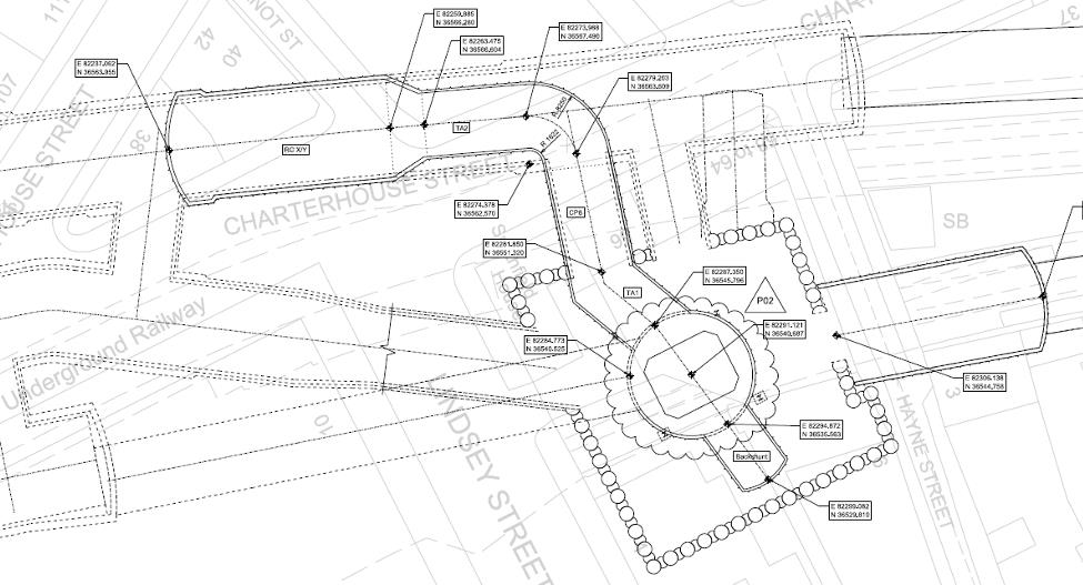
Figure 2 – Farringdon ETH SCL shaft and reception chamber
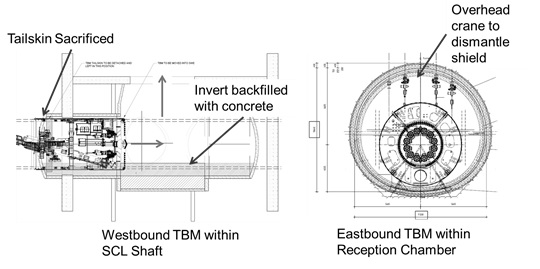
Figure 3 – Original TBM shield dismantling proposal
Of the eight proposals, the option to ‘turn and bury’ the shields best favoured the programmes for each contracts:
- A TBM first method with both shields driven outside of the permanent tunnel alignment at the ETH;
- The disconnection of the backup and pulled outside of Farringdon station for dismantling; and
- Removing all contaminants, grouting all void spaces between the shield and the natural ground, and finally backfilling the shields.
By following a TBM first principle, the tunnels bored by the TBMs would be adopted to form the SCL pilot platform tunnels whereby the lining would be sacrificed and enlarged to form the platform tunnels. This method accelerated the SCL works programme and coupled with the non-requirement for the SCL shaft and reception chamber an estimated 180 day programme for handover to the follow-on Contractor saving was envisaged.
With the ‘turn and bury’ option considered as the standout method, in May and June 2013 an environmental study was undertaken by BFK for review by the Environmental Agency to fully consider the impact of the shield burial. As part of the permissions and consents process for burial, this report detailed the proposed sequence of works and materials to be used and removed as well as those anticipated to remain after completion of the burial and strip out works. The report was accepted with the subsequent issue of Schedule 17 consent which granted approval (subject to conditions) to carry out the works.
Turn and Bury
Transit of the Western Ticket Hall
Facilitating the ‘turn and bury’ required advancing the TBMs through the newly constructed station structures to reach the burial location. This required the westbound and eastbound TBMs to break in to the Farringdon Western Ticket Hall (WTH) shafts SH-W2 and SH-W1 respectively and transit the length of the shafts before breaking out to complete the remainder of the drive.
Both shafts were formed by secant piles and featured 250mm thick (minimum) SCL constructed soft eyes (60 N/mm2 strength). Based on experience from the transit of the shafts at Bond Street and Tottenham Court Road stations, the strength and the thickness of the soft eyes were not detrimental to the TBM cutting wheel and tools. Similarly, to allow the TBMs to transit through the shafts, foam concrete was chosen as a backfill material to advance through. This comprised of a single mix of varied densities to form a stable medium of between 2-5 N/mm2 strength.
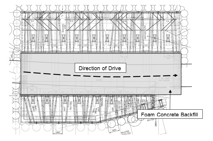
Figure 4 – Plan view sketch of foam concrete backfill within SH-W2 showing walers fixed to the secant wall
The approach, transit, and departure required specific driving parameters reducing the earth and grout injection pressures as well as thrust force accordingly. Doing so allowed the TBM to transit the foam concrete at atmospheric pressure and minimise the pressure on the supporting shutters. One particular benefit was that the foam concrete offered a stable environment to grant access to the excavation chamber and undertake inspections of the cutterhead tools as well as make any final preparation before completing the drive.
Specifically for the westbound drive, a second transit of a foam concrete backfilled structure was required for the SCL tunnel wraparound (PL2 RC Wraparound Tunnel).
TBM Shield Burial
Following the transit of the WTH, the TBMs continued to their burial locations adjacent to the ETH (see Figure 5) with the westbound drive reaching its final destination on 7th October 2013 and the eastbound on 27th January 2014.
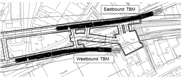
Figure 5 – TBM burial locations at Farringdon ETH
The final two advances were completed in a specific sequence to satisfactorily prepare the shield for the burial and filling of void spaces:
- Increasingly reduced volumes of foam and polymer conditioning agents and shoved the final 300 mm with minimal water only;
- Reduced advance speed (20 mm/min) and thrust force reducing risk of automatic shutdown resulting from elevated cutterhead torque levels;
- Air bled from the excavation chamber using the Overpressure Safety Valves;
- Excavation chamber filled with excavated material as far as possible;
- Retracted the cutterhead articulation; and
- Excavated material within the chamber was compacted by rotating the cutting wheel in alternate directions.
To reduce any settlement to the surface structures, immediately upon completion of the final ring build it was necessary to fill all remaining external void spaces. This included filling the excavation chamber and the annulus between the shield and the surrounding earth. For completeness, the voids within the screw conveyor and the annulus between the tailskin and final ring were also grouted.
Grouts suitable for filling the varied in size void spaces were assessed by BFK. The grout for use in the burial applications was required to meet the following criteria:
- Good for injection;
- Low bleeding behaviour;
- Low hydration heat;
- Non shrinking;
- Workability > 2hrs; and
- Compressive strength > 5MPa.
A range of grouts were considered, including specialised off-the-shelf products and bespoke mixes batched at the BFK grout plant at the Westbourne Park yard. Of the off-the-shelf products, attempts were made at mixing and injecting however potential bleeding issues and pumping difficulties. These issues arose due to the presence of granular components added to stabilise the grout when filling larger spaces as anticipated with the excavation chamber.
As a direct result, two site batched mixes were selected for use and accepted by the Environment Agency. Within the excavation chamber it was anticipated large voids would exist (particularly above the excavated material towards the crown) therefore a mix was designed which included Pulverised Fuel Ash (PFA) for added stability and bentonite for its expansive ability to fully exploit the remaining space. Conversely, for filling the annulus surrounding the shield a highly fluid mix was required encapsulate the shield. A retarder was also applied to each mix, prolonging the curing time and improving the workability as a result of the extended transport and handling time from batching to injection.
Excavation Chamber Shield
Cement = 330 kg/m3 Cement = 1085 kg/m3
PFA = 500 kg/m3 Water = 650 kg/m3
Bentonite = 35 kg/m3 Retarder = 0.5 %
Water = 650 kg/m3
Retarder = 2.0 %Injection of the site batched grout benefitted the works by use of the on-board grout injection system albeit modified to inject through the various ports on the TBM bulkhead and through the bentonite system to fill the annulus surrounding the shield (see Figure 6). To perform this, an observational method was undertaken whereby filling from the bottom-up allowed for a continual review of progress i.e. when grout flows through the port above the injection port it may be closed and the injection nozzle moved. Volumes were logged and proved comparable to estimates to confirm that all voids had indeed been filled, 24 hours later a second round of grouting was undertaken to prove no spaces remained.
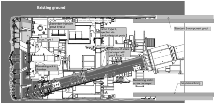
Figure 6 – Burial schematic of TBM shield
The intrados of both shields and the sacrificial tunnels remain to be filled with foam concrete.
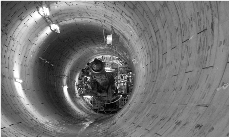
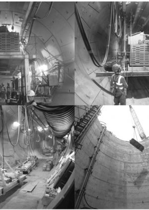
Figure 7 – Buried westbound TBM shield prior to backfilling with foam concrete
Contaminant Removal
Where practicable the various components of the 560 t shield were removed. All tanks within the shield containing oils or grease were either drained or removed where accessible and transportable, ultimately removing the potential contaminant source. However, heavier equipment namely the screw conveyor, thrust cylinders, and the main drive (including motors) remained in-place.
BFK, in discussion with Crossrail, agreed to remove as much of the oil and grease contaminants contained within the shield given the constraints (logistics, practicality, health and safety, programme, and cost). Oils and greases drained, pumped, syringed and scooped from the shield and back-up. The oils and greases were collected in sealed 1000 litre IBCs and 205 litre barrels and subsequently transported out of the tunnel for collection by certified waste carriers for processing for reuse and/or energy recovery.
The Straight Edge
Works Outline
The TBM removal options considered in the VE proposal assumed that the TBM backup would be disconnect and transported outside of the Farringdon works area for dismantling whilst allowing shared use of the WTH shafts to facilitate removal of the various backup components.
However, a full review of the works across the C300/C410 Contract led to the development of an optimized programme known as the ‘Straight Edge’. This instructed programme required BFK to meet revised completion and handover dates (contractually linked Target Dates). Tied in to this was the instruction to transport the TBM backup to the Fisher Street shaft to commence dismantling in order to release the tunnels for SCL operations as soon as practicable after the burial was completed.
Undertaking this required a switch in the programmed works to best co-ordinate the strip out with the SCL works at Fisher Street. This would entail stripping the eastbound TBM prior to the westbound TBM despite completing the drive second.
Pulling the TBM Backup
With the Fisher Street shaft approximately 1.5 km from the burial location, a specialised pulling system was needed to transport the 134 m long and 460 t backup. Working together with Mammoet, a strand jack system was adopted.
For this purpose the strand jack functioned as a hydraulic pulling device as opposed to the more traditional lifting device to which the equipment is more commonly adopted. By the opening and closing of the hydraulic cylinder (the jack) could effectively pull the backup along multiple steel cables (the strands) where each cable is clamped by two gripping heads. To facilitate the pulling as opposed to lifting action, the strand jack was mounted on a modified frame featuring rollers.
The pulling of the backup was formed of several individual pulls dictated by the alignment of the tunnel. A fixed anchor was required for the jack to pull and create the tension necessary within the cables to mobilise the 100 t pulling force (SWL). The bespoke anchors were designed and fabricated for the purpose of pulling the backup and required installing to the invert using 48 chemical anchors and a grouted connection using a rapid strength grout.
A study was commissioned by BFK to Herrenknecht to consider the various options available for pulling the backup using the strand jack system, the pulling forces necessary, stresses and forces generated whilst pulling, and the modifications required to the backup structure. Although the works were undertaken as a pulling operation as a opposed to a lifting operation, a global Factor of Safety of 4 was conservatively adopted and limited the maximum pulling force (SWL) to 41.25 t to comply with The Engineering Equipment and Materials Users Association’s document ‘Lifting Points a Design Guide’.
With the backup formed of 10 gantries each approximately 12 m long and a bridge it was possible to pull the backup in the following configurations without encroaching on the maximum pulling force:
- 2 + 2 + 7 (gantry 10 – 9; 8 – 7; & 6 – bridge); and
- 4 + 7 (gantry 10 – 7 & 6 – bridge).
In addition to the dead load of the gantries, a maximum 5 % gradient, braking force, and frictional forces were all accounted for in the calculations. Considering the pulling forces required for each scenario were no greater than the 100 t capacity of the strand jack it was deemed most appropriate to pull the gantries in the 4 + 7 configuration (see Figure 8) to maximise the programme advantage. However, doing so did necessitate larger pulling beams to support the increased load and resisting forces.
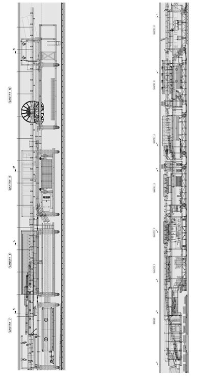
Figure 8 – Preferred 4 + 7 configuration with gantries 7 – 10 (left) and gantries 6 – bridge (right)
Modifications for pulling included the installation of two pulling beams, with the first at the rear of the backup on gantry 10 and the second on gantry 6. The beams were installed between the columns of the gantry and featuring two lugs for connecting to the strand jack using heavy duty shackles.
With a simple pin articulation between gantries 10 – 9; 9 – 8; and 8 – 7, additional beams were installed to control the steering of the gantries during pulling as one single unit. Further modifications to bridge were needed prior to disconnection from the shield with the addition of a transport bogie and bracing to support the front end and distribute the stresses and forces of transport respectively.
The pulling operation was completed in 3 phases (see Figure 9) to hand over the tunnels at the earliest possible date for the SCL tunnelling works to progress:
- Westbound TBM backup to outside of the Farringdon station works;
- Eastbound TBM backup to Fisher Street shaft; and
- Westbound TBM backup to Cross Passage 5.
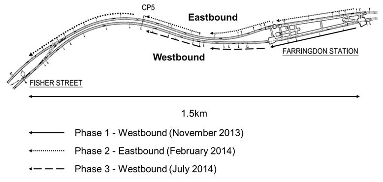
Figure 9 – Summary of phased TBM backup pulling operation
The strand jack system was managed using a computerised system with a live recording of pulling force. Analysis of the strand jack data from the first pull (westbound TBM backup outside of the Farringdon station works) identified that the maximum pulling force encountered was 9 t for gantries 10 – 7 and 27 t for gantries 6 – bridge. Using this data, the remaining two phases were completed by pulling the entire TBM backup (gantries 10 – bridge) with a combined pulling force less than 40 t. This ultimately complied with the global Factor of Safety of 4 and therefore (SWL) < 41.25 t prescribed by the initial study and further improved the programme advantage with typically 20 m/hour achieved.
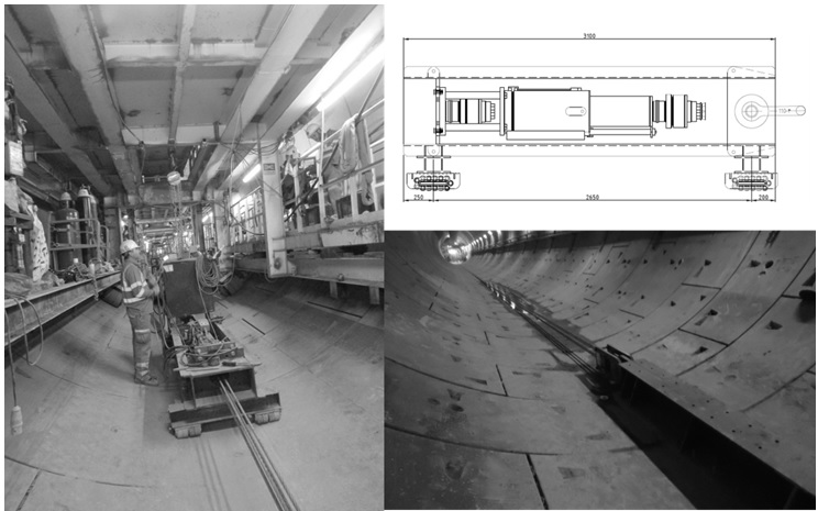
Figure 10 – Strand jack in operation (left); schematic (top right); and anchor system with strands fixed (bottom right)
The ‘Monorail’ System
With the decision to dismantle the TBM backup at Fisher Street in-place, BFK commissioned Herrenknecht to design a bespoke overhead craneway (commonly referred to as the ‘Monorail’ system) to facilitate the dismantling of the individual gantries.
The use of an overhead craneway was considered the most practical and simple means of dismantling the backup allowing a safe means of top-down access. The task was considered an intensive lifting operation which was not simply the reverse of the assembly given the limited headroom when working within a tunnel as opposed to a cavern, shaft, portal, and the like.
Key to the design of the craneway was the maximum load supported by the rings. A review by the permanent works designer for the bored tunnels (Contract C122) highlighted that the maximum load accommodated per ring was to be no greater than 16 t (SLS). Further design considerations included the potential location of ring segment joints (mainly radial joints) to ensure sufficient fixity and redundancy (possibly requiring the beam to be able to span up to 3.2 m between anchors to span a single ring). To accommodate removal via the shaft adit and Cross Passage 5, the design of beams accounted for the steelwork propping to avoid any clashes.
The final design comprised of three individual beams (see Figure 11) each operated by two individual hoists separated by a spreader beam to dismantle a single gantry at any one time. Two parallel beams using four 8 t hoists were designed to separate the decks forming a gantry (top and bottom) and lift the larger components (refuge chamber, grout tanks, electrical cabinets, etc.). A third single beam with two 12.8 t hoists offered considerable flexibility to transfer and leap-frog materials and components for removal via the shaft adit and Cross Passage 5.
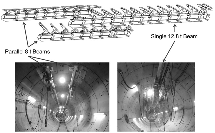
Figure 11 – Sketch of overhead craneway system
The design of the monorail was required to follow the alignment of the tunnel and operate along gradients of up to 2.5 %. Although the tunnel geometry and ring build information was available to design the craneway, on-site fabrication of individual beams was necessary to accommodate site conditions i.e. ring roll, segment lips and steps. Overcoming the tunnel gradient led to the adoption of air-driven hoists and a gear track installed to each craneway beam.
With a considerable amount of site works, quality control was fundamental to ensure a right first time approach. Strict control of lifting and loading of installations was employed throughout by means of pull testing 50 % of all anchor installations and the issue of permits (to load). Similar controls for site-based welding were applied with all welding undertaken and supervised by coded welders and each weld was visually inspected as well as subjected to a Magnetic Particle Inspection (MPI) in accordance with National Structural Steelwork Specification for Building Construction 5th edition (CE Marking Version). Finally, a 125 % proof load test was performed to test the system and hoist operation to comply with the Lifting Operations and Lifting Equipment Regulations 1998 (LOLER).
TBM Backup Removal
The sequencing of the dismantling required working along the direction of the drive from the rear of the backup (gantry 10) to the front (bridge). These works were reviewed in partnership with Herrenknecht to best organize the dismantling of each gantry using the overhead craneway.
Transporting each gantry individually beneath the monorail saw the implementation of a 10 t air winch fitted to the tunnel invert. By connecting the winch rope to a towing point on each gantry, once disconnected from the ‘train’ it was possible to pull the gantry steadily along the tunnel and steering the bogies accordingly.
The backup was formed of three principle sections:
- Gantries 10 – 7 featuring an open bottom deck;
- Gantries 6 – 2 featuring a closed bottom deck; and
- Gantry 1 + Bridge.
Much of the backup was dismantled following a streamlined process. This encompassed firstly removing small items including cables, pipes, etc. before separating the decks, removing the larger items such as the refuge chamber or electrical cabinets, and finally cutting the frame. With the frame not being salvaged and therefore deemed as scrap, set cutting lines were advised by Herrenknecht to safely cut each member and form manageable packages for transportation. All works were undertaken in such a manner to ensure that the loads remained below the 16 t requirement specified by C122.
Although the positioning of the monorail was intended to align with the original lifting lugs used during the assembly of the backup however with limited headroom and on the more complicated gantries it was sometimes the case the original lifting lugs could not be used. In these instances, new lugs would be welded on to suit. Generally, Section 1 (gantries 10 – 7) required the top and bottom decks to cut before dismantling the decks and supports. It is important to note that the open bottom deck to these gantries necessitated the installation of supports prior to separating the decks. For Section 2 (gantries 6 – 2), the top and bottom deck were simply unbolted with no supports required as these gantries were more robust structures given that they supported the larger components used during operation of the TBM.
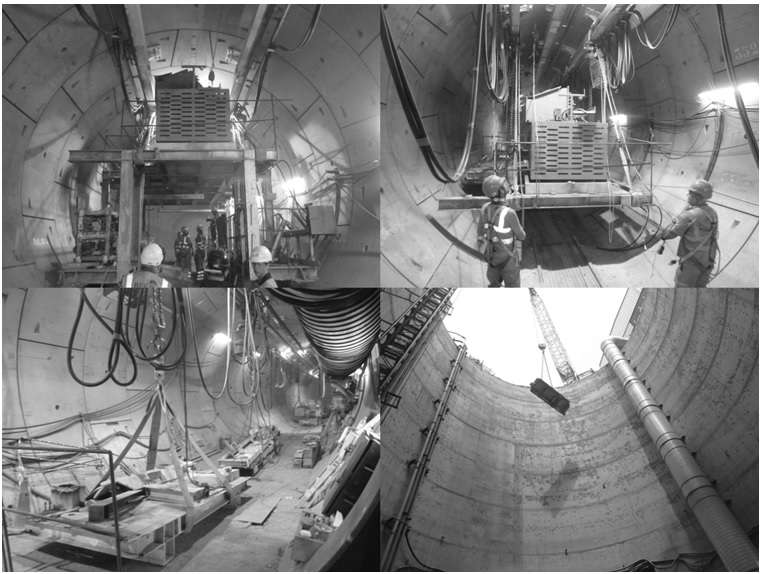
Figure 12 – Dismantling of the eastbound TBM backup and removal via the shaft
Section 3 (gantry 1 and bridge) was always considered the most intricate part of the backup, requiring a considerable review by both BFK and Herrenknecht. This was due to the presence of two 19.5 m longitudinal beams running the length of the bridge and fixed to the front of gantry 1. Consequently, pulling the structure beneath the craneway in the original form was not possible and a phased approach was implemented (see Figure 13):
- An additional bogie was installed at the rear of the bridge;
- A simple pull rod was fitted to link both the front and rear bogies and ensure both bogies act together by moving at the same time and not allowing the bridge to roll away;
- The jacks on the bogie frame were extended to support the load of the rear of the bridge so the two main longitudinal beams did not require the support of gantry 1;
- Having obtained a clearance of approx. 5 cm between the longitudinal beams and gantry 1 the support frame of the second bogie was welded onto the bridge to allow the pressure of the jacks to be released;
- As gantry 1 was released, the winch was used to pull the bridge and gantry 1 together.
- With the longitudinal beams running the length of the upper deck of gantry 1, it was then possible to cut longitudinal beams into smaller lengths;
- Gantry 1 was pulled beneath the craneway and dismantled in a similar fashion to previous gantries with the cut sections of the beams also dismantled further;
- The remaining sections of the longitudinal beams fixed to the bridge were separated and suspended using lifting eyes installed to the tunnel lining;
- With the longitudinal beams supported, the bridge was pulled beneath the craneway and dismantled; and
- Finally, the longitudinal beams were lowered and cut on the tunnel invert.
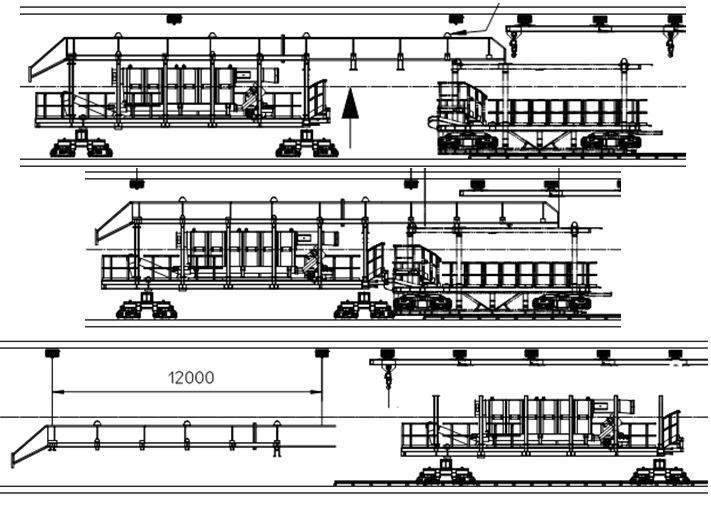
Figure 13 – Gantry 1 and bridge dismantling sequence with installation of bogie (top); marriage of gantry 1 and bridge (centre); and dismantling of bridge beams (bottom).
Works on the eastbound TBM were completed on 19th July 2014, with the backup removal operation lasting 8 weeks at an average of 4 days per gantry. Ultimately the works were completed 4 weeks ahead of the programme and released the tunnel for SCL works earlier than anticipated.
As for the westbound TBM, with the backup removal undertaken from Cross Passage 5 as opposed to immediately adjacent to the shaft adit, increased logistical challenges were presented. With multiple tunnel construction activities taking place in parallel (SCL tunnelling, Secondary Lining, and First Stage Concrete) use of the tunnel and shaft for the backup removal was restricted. To overcome the restrictions, the TBM was dismantled in to smaller sizes for temporary storage within the tunnel and subsequently removed when access was made available. Considering this, the programme for tunnel handover was achieved with the works completed on 10th December 2014 with the backup removal operation duration matching that of the eastbound TBM.
Conclusions
The option of not burying the TBM shields at Farringdon and removing the backup via the Fisher Street ventilation shaft had the potential to create significant delays to the works within both the C300 and C435 contracts. By undertaking a thorough review of the possible options, it was possible to expedite the SCL works programme considerably as well as bring forward key handover dates for follow-on Contractors.
Although considered a common occurrence in the tunnelling world, adopting the TBM shield burial and backup removal required an in-depth review of the techniques available. Following considerable temporary works design, appropriate in-tunnel solutions were developed and successfully implemented.
Grouting the shield was successfully performed with acceptable volumes injected matching estimates. The adaption of the strand jack system proved highly capable and recommended for pulling the entire backup at a relatively fast pace. Similarly the development of the overhead craneway was well suited to the process of dismantling the backup and with all items lifted remaining below the 16 t (SLS) loading capacity of the tunnel rings.
Although normally dismantled overhead within a shaft or reception chamber, it is considered for future applications that burying of the shield may prove a useful tool upon completion of a drive. However, with the increased requirement for large diameter bored tunnels beneath urban environments and advanced TBMs to excavate tunnels in difficult ground conditions, improved considerations for in-tunnel dismantling should be applied to TBM designs. Further review of the TBM arrangement and in-tunnel disassembly methods would lead to better salvaging of TBM components promoting wider re-use as opposed to the single drive use that is commonplace within the industry.
The logistical challenges posed by working in tandem with other tunnelling operations on a complex major project within a restricted work space should be fully appreciated. These challenges may lead to programme conflicts, but it is the communication between operational staff to identify opportunities and a committed workforce to deliver the works that have proven key to success.
-
Authors

