C350 Pudding Mill Lane
Document
type: Technical Paper
Author:
Alistair Briffett
Publication
Date: 10/11/2015
-
Read the full document
Introduction
Contract C350 – Pudding Mill Lane Portal involved the construction the north eastern cut & cover tunnel portal that brought the new line up above ground and tied it into the existing Network Rail corridor between Stratford and Liverpool Street (refer to figure 1). The proposed alignment of the tunnel portal clashed with the existing DLR station at Pudding Mill Lane. This necessitated a new station and viaduct to be built south of the pre-existing station and a reinforced earth embankment created to the west which would allow the DLR line to be slewed and the old station demolished. The cut & cover portal could then be progressed along with the associated structures required to bring the line up into the Network Rail corridor. The site had previously seen heavy industrial use in its time including having incarnations as a gasworks, chemical works and notably the Bow Power Station. This industrial use has seen significant levels of hydrocarbon contamination of the soil. This contamination permeated throughout the River Terrace Deposits.
The general site geological profile was of 2m of made ground followed by 4-5m of River Terrace Deposits. This was followed by a thin layer of the London Clay formation before the Lambeth Group geology was encountered. This ranged in thickness from 8-12m. The Thanet Sands were struck at varying depths across the site but generally were encountered at a depth of 28-30m below commencement level.
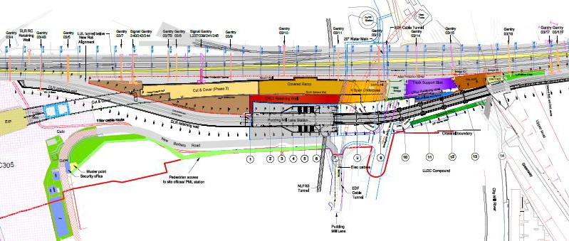
Figure 1 – Site overview
The utilisation of CFA piling
The presence of the sand channels within the Lambeth Group and also the fact that the piles would be founded in the Thanet Sands meant that stability would be an issue were they to be constructed as open rotary bore. The design depth and diameter of many of the project’s piles meant they could be constructed via CFA technique. Given the sites proximity to rail assets, CFA was ideally suited as it required far less lifting operations to construct a pile. It also judged to be the most programme effective and cost efficient way to construct the piles and as such was favoured where possible.
CFA piling was utilised on the following structures:
The new DLR station, CRL retaining walls and viaduct required the installation of 457no CFA piles ranging diameter from 600mm to 900mm and in depth from 21.5m to 29.5m.
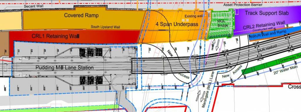
Figure 2 DLR station and associated structures
The transfer slabs, upon which the earth embankment would be constructed, were originally detailed to be stone columns but this was revised due to settlement criteria to consist of a raft of 425no 750mm diameter piles. These were constructed to a depth of 25.5m.
The associated structures required to bridge the Crossrail line across Pudding Mill Lane, Marshgate Lane, and City Mill River, required 280 piles. They ranged in diameter from 750mm to 1050mm and depth from 22.5 to 30.5m
The presence of the Thanet Sands posed a significant risk to the operation of CFA piling as it had a tendency to grip as it settled in and around the auger string as it was progressed down. Multiple contractors have been forced to abandon auger strings once the sands had taken grip of them, with the rigs unable to generate enough torque to release them. To mitigate this risk, Bachy Soletanche employed the large Soilmec SF120 and CM120 CFA rigs with their increased torque. In addition to this care was taken not to commence a pile prior to sufficient concrete being onsite to complete the pile being drilled. This ensured that the augers were left stationary for the minimum amount of time, thus reducing the time the sands had to settle in and around the stationary augers.
The design of the reinforcement often required increasing bar diameters to allow them sufficient weight and rigidity to be plunged in one section. With cages requiring to be plunged up to 17m, any design utilising less than 25mm bar would have had to be increased to allow it to be constructed via CFA technique.
On occasions, pockets of soft ground were encountered. These pockets often resulted in the concrete slumping under the hydraulic head of concrete. It was not uncommon for the concrete level within the piles to drop by up to 500mm as the concrete pushed out into the soft river terrace deposits. Fortunately the cut-off level was significantly below commencement level so the integrity of the concrete below this level was never compromised. It did however have the effect of slumping the cage beyond the permitted tolerance. The site team over came this by hanging the cages off the lifting band which was relocated to the top of the cage rather than at cut off level.
Cut & Cover Tunnel – Diaphragm wall
The diaphragm wall that formed the southern wall and the initial section of the north wall of the cut and cover portal had been installed under contract C248. Due to a programme delay in diverting an 11kV cable that obstructed the last elements of the wall, Crossrail took the decision to assign the last remaining sections to the C350 contract rather than have two principal contractors onsite. As a result Bachy Soletanche installed the remaining 95lm of 800mm thick wall to a depth of 18m.
The footprint of the wall was in very close proximity to the DLR and Network Rail assets. This created significant logistical problems with the orientation of the grab and support cranes. While plotting of plant and cranes per panel on CAD was implemented and used to demonstrate to DLR and Network Rail that the panels could be constructed without the requirement for possessions, getting the cranes into these plotted positions without breaching the restrictions was testing. The site team in conjunction with the site representatives from DLR and NR utilised laser distance measures to physically check each movement onsite prior to it being undertaken.
The design of the wall utilised short panel sizes to minimise the risk of causing differential settlement to the adjacent rail lines. However, a lack of understanding of how panels are excavated meant that many of the panel lengths opted for were not suitable for the readily available grab jaw dimensions. A traditional D-wall panel’s length is such that it either requires a single bite, or two bites at either end followed by a clearing bite down the middle. By selecting a panel length greater than the width of the grab jaws but less than the width of two, it forces the operator to take one bite down one side and then attempt to clear the remaining section with the grab constantly wanting to kick off back towards the void. While it can be done by utilising clamps on the grab to allow it to run down the stop end, it has a significant impact on the production rate and can affect quality of the wall joints. The detailing of these panel lengths would have greatly benefitted from direct input from a diaphragm walling contractor who could have assisted with selecting panel sizes to best suit current methods.
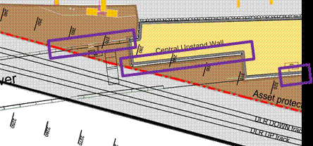
Figure 3 Bachy elements of diaphragm wall
Transfer slab – Rotary bore piling under bentonite
On the Northern transfer slab Crossrail perceived there to be a risk that constructing the piles within 3m of the DLR retaining wall would result in movement of the wall exceeding its trigger levels as a result of possible flighting that is potentially associated with CFA. It was deemed too great of a risk by CRL who opted instead to have the piles constructed rotary bore under bentonite. The thought process was that by casing down through the unstable River Terrace Gravels to the clay and Lambeth Groups below, the risk of potential collapse would be negated. The pile excavation could then continue under bentonite from there down to toe level.
The 900mm diameter design of 41no bentonite piles to be installed to a depth of 33-35m was developed in response to this concern. The depth to the clay and residual concern regarding the method of installing temporary thin wall casings meant that segmental casing had to be employed. The design diameter however did not lend itself to suit the readily available segmental casing sizes. It was fortunate that Bachy Soletanche had some rare 1m casings in stock, otherwise the pile would have had to be constructed to the larger 1180mm diameter which would have had potential implications for a redesign due to reworked pile spacings. Had the designers involved a specialist contractor at an earlier point in the design phase, they could have together developed a solution that meet the design requirement but also took advantage of those tools readily available (see table below) and techniques that would have been the most cost effective. While designers can optimise their designs to minimise the material costs, without insight into the construction processes, they can be inadvertently increasing the overall build cost of a project.

Figure 4 – Dwall operations
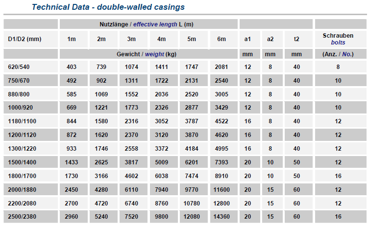
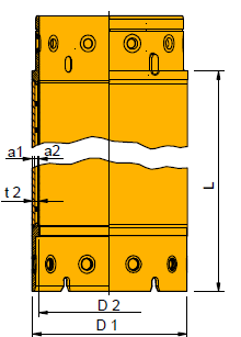
Figure 5- Stock sizes of segmental casing
Cut & Cover Tunnel – Cased CFA (CSP) Secant piling
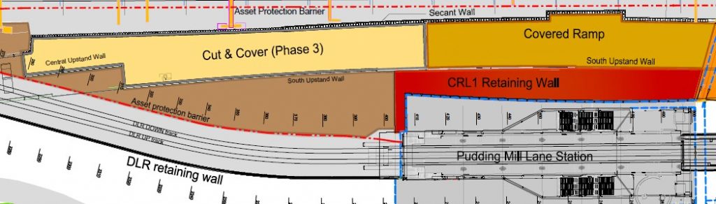
Figure 6 – Secant wall layout
Where the northern wall of the cut and cover tunnel drew within 10m of the Network Rail corridor there was considerable concern that the construction of this wall may lead to differential settlement of the adjacent rail lines. The client’s design team opted for a secant wall solution.
The wall design required involved the installation of 1050mm diameter hard-hard wall with piles extending down 20.5m. Again the design utilised a diameter that did not match the readily available stocks of segmental casing. To construct the wall by traditional rotary bore piling utilising specially
built segmental casing would have had significant cost and programme implications to the project. The proximity of the piles to the Network Rail boundary (in some places as little as 2m from hoarding and 7m from the running rail) would have also made it difficult to construct the piles during normal working hours. The width of the site and angle at which a traditional crane would have needed to be orientated, to avoid it’s collapse radius crossing over rail assets, necessitated that the works be constructed during engineering possession hours. The possession hours were only available on weekends and not always on consecutive weekends. This when combined with the restrictions of secant wall sequencing would have resulted in Bachy attempting to cut some of the female piles up to 28 days after they were first constructed. It would have greatly increased the risk of cracking the female piles and would also have drastically increased the drilling times thus exacerbating the problem of what could be achieved during the limited hours of the possession. The number of lifting operations associated with traditional rotary secant piling would been difficult to manage with the limits that were imposed by Network Rail.
Figure 7 – Typical secant wall piling sequence
Bachy Soletanche decided that Cased CFA (CSP) piling would be best suited given the operating environment stated above. At time of tender the piles were outside the capabilities of the available CSP rigs in the country and thus required a larger Bauer BG46 rig to be sourced from Germany. The rig had sufficient torque to cut the female piles to the required depth and enough ballast to take the weight of the full drill string and rotary table.
To overcome the issue of the bespoke pile diameter, Bachy commissioned a custom drill string and full length casing to be fabricated. The full length casing was of thin wall construction with a cutting shoe connected to the bottom. The cost of a full length casing was significantly cheaper than that of bespoke segmental lengths but had the disadvantage of being cumbersome to fix to the rig and was not as robust.
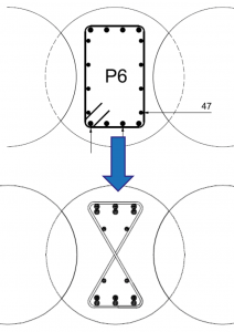
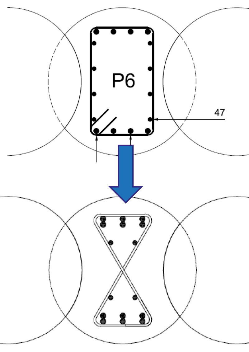
Figure 8 – Butterfly detail
The design also called for the female piles to be reinforced to the full depth of the pile. The original detail for these piles in the construction drawings called for a square cage, however this increased the risk of striking steel during the excavation of the male piles as they cut through the females. The tolerance on placement of the female cage to ensure that the clearance between the outside edge of the cage and the cut was considered too tight. Together with the designers from C152, a butterfly shaped caged detail was agreed upon during pre-construction planning. It was fortunate that it was a detail that the designer had seen before on a previous contract Bachy had conducted for them as it dramatically reduced the time it took to get approved. Other potential cost saving initiatives were tabled but declined due to the amount of time it would have taken to get these other proposals approved by a CAT 3 checker. As it was the CAT3 checking of the steel detailing caused significant delays to the construction programme. It had a significant impact on the projects ability to implement cost engineered solutions as the time taken to approve any such solution was such that the window of opportunity within which these solutions could be applied, and be effective, was often missed.
Constructing the 282 wall piles via CSA meant that 282 pile cages had to be plunged to a depth of 20.3m into piles that had been constructed through the Lambeth Group with its sandy layers. The sands had the effect of drying out the concrete reducing its workability and potentially impeding cage plunging. It made for challenging conditions through which to plunge reinforcing cages. To give the best chance of ensuring that the cages were successfully plunged to depth, Bachy spent extensive time with their selected concrete supplier developing a high flow concrete supply with a 5hr workable life that met the requirements of the specification. Furthermore, the team looked to cut down the time it was taking to concrete the piles to reduce the time between when the concrete at these sandy layers was placed and when the cage was plunged.
The restrictions placed on crane’s slew radius for works taking place near rail assets, when combined with the narrow site and close proximity to the Network rail line, required a unique solution to allow for the cages to be installed without impeding pile installation. Bachy opted to utilise a leader rig to lift and install the cages. The leader rig due to its classification as a piling rig, was able to move and orientate itself towards the railway lines unlike a traditional crane. This allowed for the piles to be constructed without impeding the CSP rig and negated the potential significant impact to the construction programme.
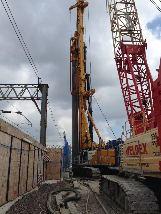
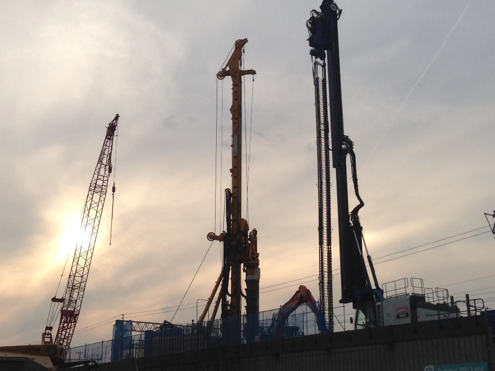
Figure 9 – BG46 in close proximity to rail assets

Figure 10 – Leader rig with cage suspended
Conclusion of lessons learnt
Pudding Mill Lane is significant in the fact that it utilised multiple different techniques in a very challenging environment, allowing for parallels to be drawn between the viability of one technique over that of another. The project demonstrates that heavy piling can be effectively conducted adjacent to live rail assets but requires significant levels of forward planning to mitigate the risk posed to these assets.
With respect to what could be done better, there is one consistent factor that has lead to issues along the way with this project. It is the apparent lack of understanding by the design community of the piling techniques and processes and their limitations. The impact a foundation design can have on the cost and programme by not being suited to construction by methods readily available cannot be understated.
Large schemes such as Crossrail in future would greatly benefit from having pile designs reviewed for practical implications by a working group consisting of FPS members. Such a working group could identify at an early stage potential issues with designs and also cost saving solutions. This early identification would allow for sufficient time to have the changes implemented and approved before they have a chance to impact construction programmes.
-
Authors