Comparison of Drilling Methods used for TaM installations in London Clay
Document
type: Technical Paper
Author:
P Pérez Lupi MSc, E Lewis MEng, J Adetoye BEng, X Gonzalez TEd, N Gallego Ramirez MSc, Z Munn BEng, D Campos MSc, ICE Publishing
Publication
Date: 03/11/2014
-
Read the full document
1. Introduction
Horizontal Drilling operations to install TaMs (Tube à Manchettes) pipes to facilitate compensation grouting activities for mitigation measures required for Crossrail were undertaken from vertical 4.5 m diameter shafts in Central London. It is known that the drilling operations to install TaMs is a source of settlement and heave and to that end, this paper compares the methods and observations undertaken at the commencement of drilling operations to ensure that the remainder of the work could be completed using a method that was efficient and suitable for the site conditions.
2. Scope
Crossrail contract C300/410, the Western Tunnels section of Crossrail Central, consists of the construction of 6 km of twin bored running tunnels from Royal Oak portal through to Farringdon Station, a crossover tunnel at Fisher Street, and the station and platform tunnels at Bond Street and Tottenham Court Road stations, where connecting shafts, station concourses and adits, are being built by means of excavation and SCL (sprayed concrete lining) in between the Western and Eastern station boxes.
There have been several major tunnelling projects in London in recent years including the Jubilee Line extension, the Channel Tunnel Rail Link and the Heathrow Express. As a result, there is a good understanding of how London Clay reacts to the excavation of tunnels and underground structures. As part of the detailed design, ground movement predictions were calculated from settlement profiles expected from each stage of construction. Short term ground movement predictions are based on ‘Green Field’ conditions as the stiffness of the buildings and the effect of the stiffness of foundations on the soil are assumed negligible making the assessments conservative.
From the settlement contours calculated, damage assessments are then made to ascertain the potential damage that the effects of tunnelling could have on the aboveground and underground infrastructure, in order to then design mitigation measures as necessary. Building damage is categorised using the tensile strain approach.
As a measure to mitigate the ground movement and the potential damage it could cause, an area in excess of 50’000 m2 was specified to be controlled by compensation grouting in selected areas around the stations, for the passage of the tunnel boring machines, the SCL tunnelling works, and station box excavations. The extent of compensation grouting for both areas is limited to the 10 mm settlement contour and the duration of the treatment is linked to the works and until the rate of settlement is less than 2 mm per year .
3. Site Constraints
The Compensation Grouting shafts within the C300/410 contract are located in areas of Bond Street, Tottenham Court Road and Holborn. These grout shafts are located in major urban environments which increases the difficulties for the site operations. The working areas are reduced to a minimum in order to reduce the impact in the adjacent third parties. The reduction of the working area has had an impact on the diameter of the grouting shafts which have been reduced to 4.5 meters instead of the usual 6m diameters required. The average depth of the shafts is 15 meters.
Drilling, spoil handling and disposal, limited room available, access restrictions and environmental impacts are some of the key issues to consider when determining the best method to drill TaMs in shafts located in the central London.
4. Compensation Grouting
Compensation Grouting is a method of controlling ground movements in clay. It has been successfully used on projects such as the Waterloo Victory Arch, Jubilee Line Extension and the Heathrow Express. The process of compensation grouting involves the injection of grout into the clay at pressure, in between the level of infrastructure that is being protected and the cause of ground settlement i.e. tunnelling. The grout, under pressure, is injected via small ports at set intervals within the tube à manchettes, this grout will find the natural occurring fissures in the clay and expand them, minimising the settlement and potentially causing heave, depending on the volumes injected. The grouting operations are controlled from a central grout shaft, where radial holes are drilled and TaMs are installed and grouted in position.
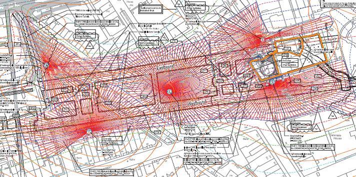
Figure 1: Bond Street Station TaM Layout
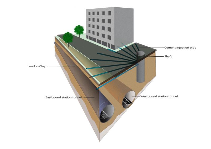
Figure 2: 3D section showing the relation of TaMs, in an urban environment
The TaMs comprise 52 mm diameter steel tubes typically at 2 m lengths, which are screwed together and inserted into the boreholes to the required lengths. TaM lengths on the Crossrail project are typically 50 to 90 m and contain small ports, drilled in the intrados of the steel tube at regular intervals, typically every 500 mm. The ports are covered with a thick rubber membrane that lifts with the pressure of the grout being injected and closes once the grout has been injected, working like a one way valve. During the grouting operations, double packers are inserted into the TaMs and expanded, so that any individual port on a TaM can be grouted from, accurately targeting the settlement real-time, as identified by the monitoring system. Multiple phases of grouting can be carried out from the TaMs, helping to mitigate the effect of tunnelling activities until the rate of settlement has decreased significantly.
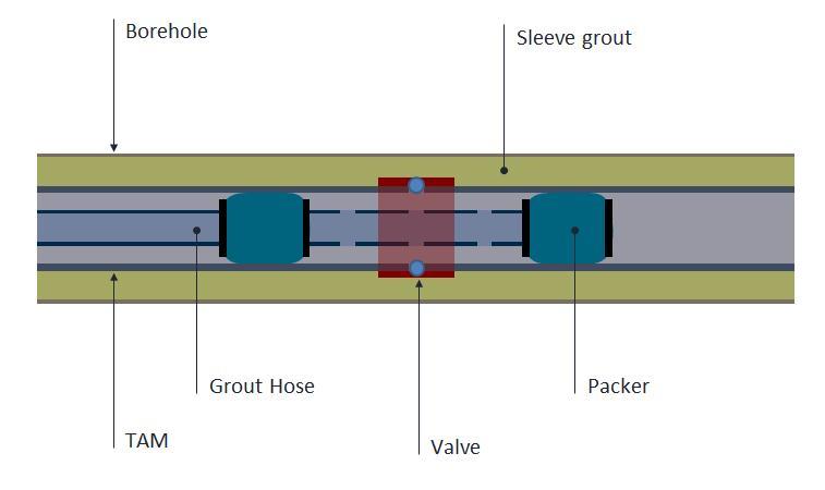
Figure 3: Cross section of TaM with inflation packer
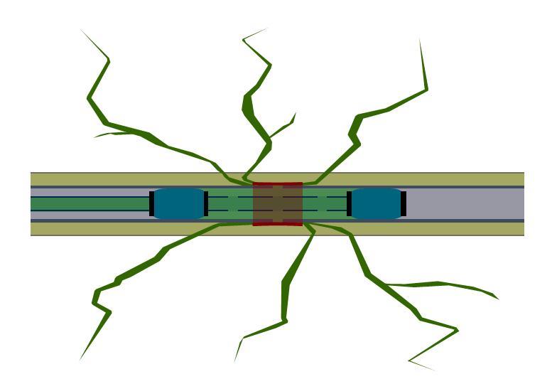
Figure 4: Cross section of TaM with inflation packer injecting grout
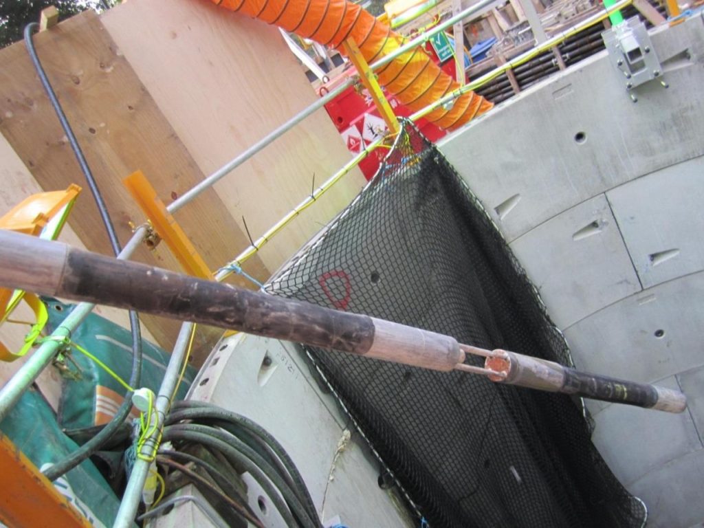
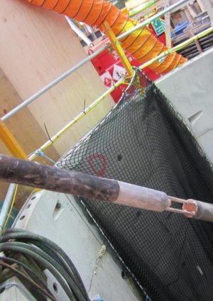
Figure 5: Photograph of inflation packer
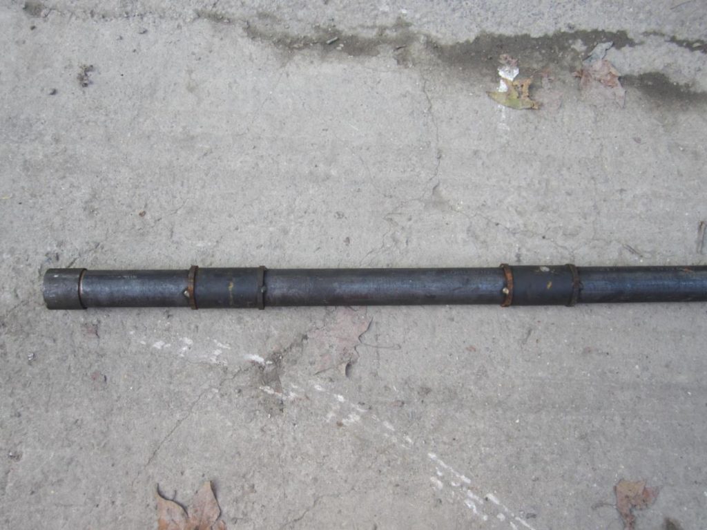
Figure 6: Photograph of tube à manchettes pipe
With a total of 45’000 m of TaMs to drill and install prior to the construction and excavation of the tunnels and stations, a total of 13 grout shafts are being used on contract C300/410.
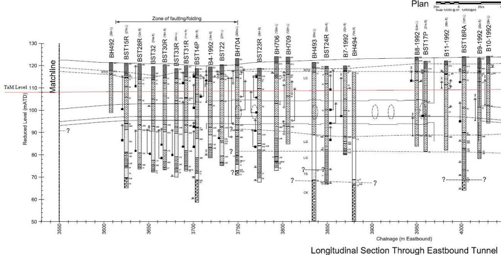
Figure 7: Profile of the clay in relation to the structures and the materials overlying the clay
The drilling of the TAMs required careful control of the placing of the boreholes, with the drilling accuracy and location required to be reported. The accuracy and location was determined by using a Reflex Maxibor instrument that calculates the spatial coordinates along the drill hole path based on optical measurements of direction changes and gravimetric measurements of dip changes.
5. Instrumentation and Monitoring
In order to monitor the ground movements that occur from the TaM drilling, and to subsequently control and manage the compensation grouting operations during the main works a large amount of Instrumentation and Monitoring (I&M) had been specified and installed in the site area.
The I&M used, varies in function from asset protection to ground monitoring. The measurement of heave and settlement during compensation grouting is primarily measured using a hydrostatic levelling cell (HLC) system due to its accuracy and data transfer capabilities, there are also secondary monitoring instruments used to validate and back up the HLCs. Other methods of measurement for the monitoring of the compensation grouting works include precise level points installed in pavements and BRE studs, which are installed on buildings. These points are then read using digital levels. Further monitoring methods include Automated Robotic Total Stations which read prisms installed on the neighbouring building facades. The monitoring management plan for each location provides the primary method of measurement and the associated trigger values.
The hydrostatic levelling system’s pressure cells, measure pressure differences versus a reference measuring point. The pressure changes recorded can then be converted into height differences. The reference level is defined by the liquid horizon in a header tank (liquid reservoir). All measuring points are connected together by a water tube which also connects to the header tank and thus the reference level. The sensors utilised are capacitive pressure devices, which are stable and reliable. The analogue signals of the pressure devices are captured and converted into measured values which are displayed in the monitoring system. The cells are installed typically within basements on structural walls or beams. The instruments have a vertical measuring range of 500 mm and a resolution of 0.02 mm. The use of over 800 cells in the Bond Street area requires a complex reference and management system, where cells are read every 15minutes, though they are able to be read every 30 seconds if required.
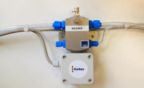
Figure 8: Hydrostatic Cell measurements over time
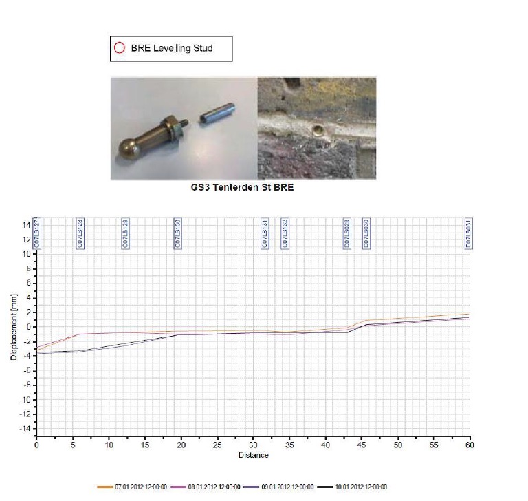
Figure 9: BRE Levelling Stud- Plot BRE
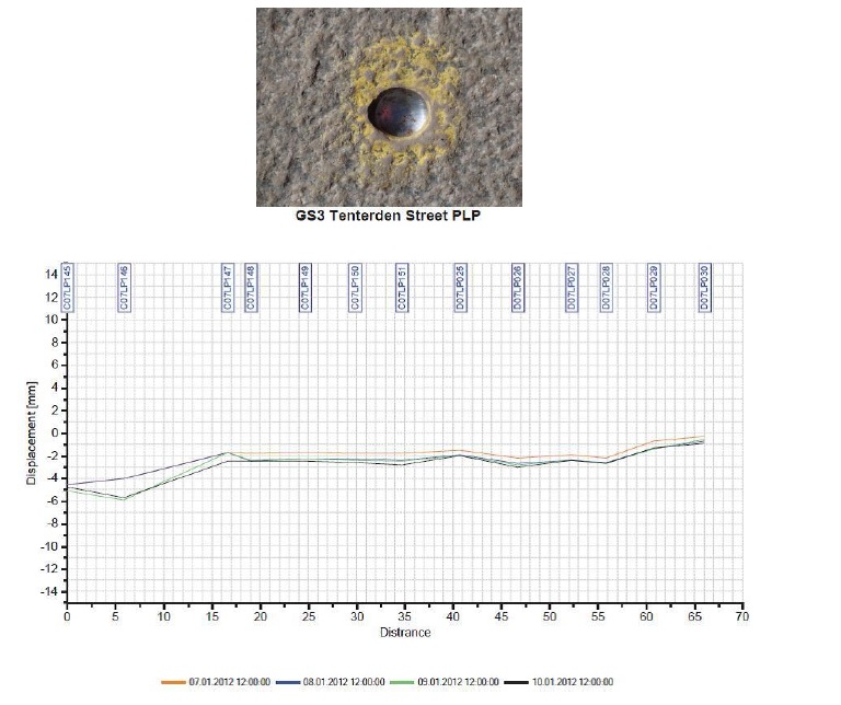
Figure 10: PLP Precise Levelling Point- Plot PLP
6. Comparison of Drilling Methods
Two methods of drilling have been implemented at Bond Street, water flush drilling and auger drilling.
Partially cased, water-flush rotary method – Bond St Shaft 3
Drilling operations commenced in Bond Street from grout shaft 3, using drilling methods used on similar projects from the 1990’s, and also as implied by the specification. In variance to these past projects, temporary drill casings were generally installed in accordance with the specification: 50% of the bore for holes of up to 40 m, and all but the last 20 m of longer holes. This varied occasionally with a small number of holes being fully cased (for heave mitigation reasons). Due to the length of casing required, drilling with a polymer flush was initially used, but quickly suspended due to the associated operational difficulties coupled with the lack of available compound space to effectively deal with the flush arisings.
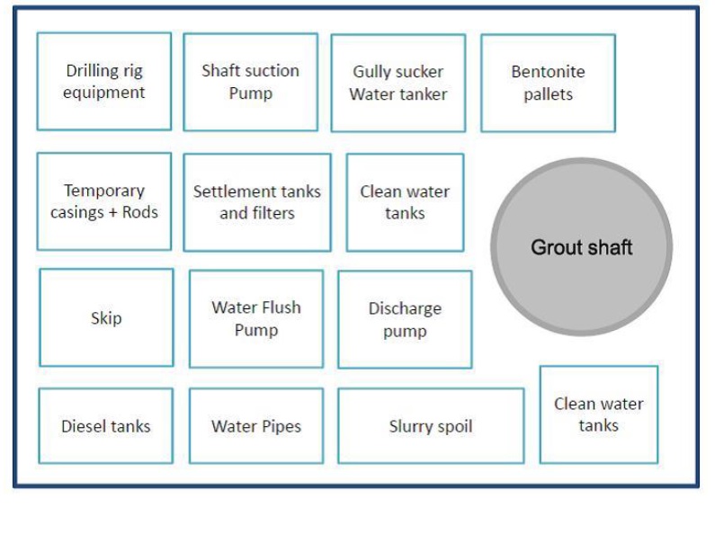
Figure 11: Schematic site layout for the water flush TaM drilling method
Partially cased, rotary auger method – Bond St Shaft 5
Grout shaft 5, was drilled using the partially cased, rotary auger method. The rig was fitted with a double rotary head, and drilling commenced with an air flush to assist with the installation of the drill casing, as often used in central Europe. Following an initial heave issue, drilling continued successfully without the associated air flush. As a result of omitting the air flush, installation of the drill casings was increasingly difficult and was short of the specification requirements, but bore hole deviations were not significantly affected with the reduced casings.
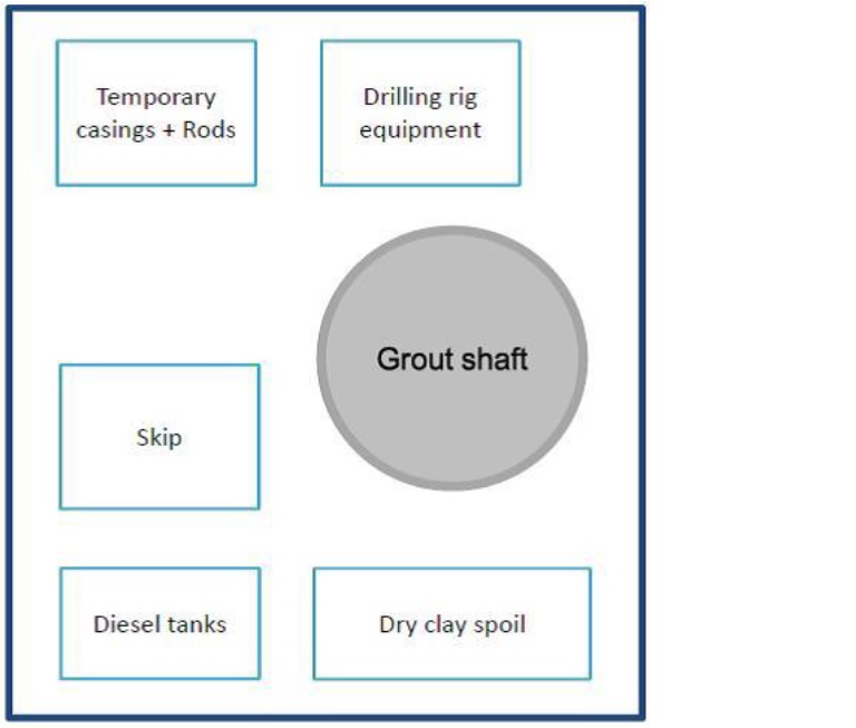
Figure 12: Schematic site layout for rotary auger TaM drilling
Quality / Drilling accuracy
There are significant tolerances placed on the installed location of the TaMs. Exclusion zones have been specified above the crown of the tunnels and below the top level of the clay. There are also maximum spacing tolerances between adjacent TaMs to ensure complete coverage of the identified grouting zones.
The layout of the TaMs means that TaM pipes are being installed to lengths of up to 100 m. Drilling to these lengths means that holes may deviate in location, and in some cases unidentified obstructions are encountered
The accuracy and location of the as built TaM locations are checked using a Reflex Maxibor instrument that calculates the spatial coordinates along the drill hole path based on optical measurements of directional changes and gravimetric measurements of dip changes.
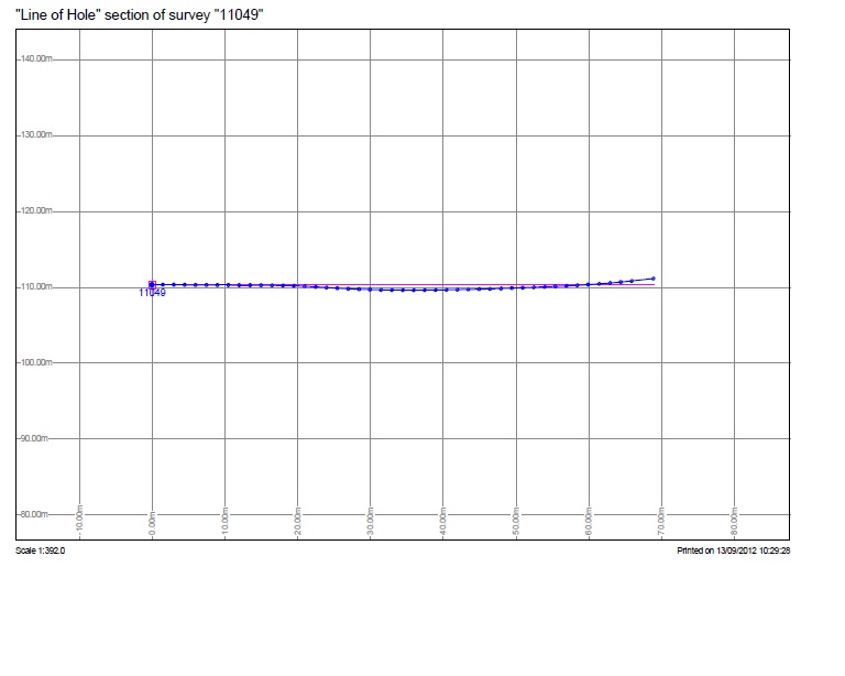
Figure 13: As built TAM showing vertical deviation
The works specification required that the chosen drilling method should have the casing advanced as far as necessary to ensure that the following tolerances on elevation were achieved: ±250 mm at 30 m distance from the shaft wall, ±500 mm at 50 m and ±750 mm at 65 m from the shaft. The control of drilling direction had to also realise an accuracy of 0.5 m in plan of its theoretical location in order to ensure complete coverage of the identified grouting zones. During the drilling operations, 10% of the boreholes had to be re- drilled to comply with the specification requirements on accuracy for both methods.
Ground Movements
During the TaM drilling at Grout Shaft 3, where the water flush drilling system was used, evidence of ground heave generated during the drilling and subsequent sleeve grouting operations were observed. The water flushing pressures during the drilling phases needed to be carefully controlled to minimise the heave generated. The auger method in comparison, generated a gradual, but significant, amount of settlement during the TaM drilling process, and no heave was observed during the sleeve grouting operations. These gradual settlements have been controlled further with the introduction of a secondary phase of grouting. Additional compensation grouting was also used in areas known to have poor ground conditions and where adjacent works were occurring concurrently.
Where settlement has continued, there has been a need to undertake routine corrective grouting operations to recover the gradual settlements during the course of the drilling process. Due to the limited compound space available at all of the grout shaft sites, it has not been possible to undertake grouting operations concurrently with the drilling. Hence, treating this settlement with phases of grouting has had the potential to cause significant delays to the TaM drilling programme.
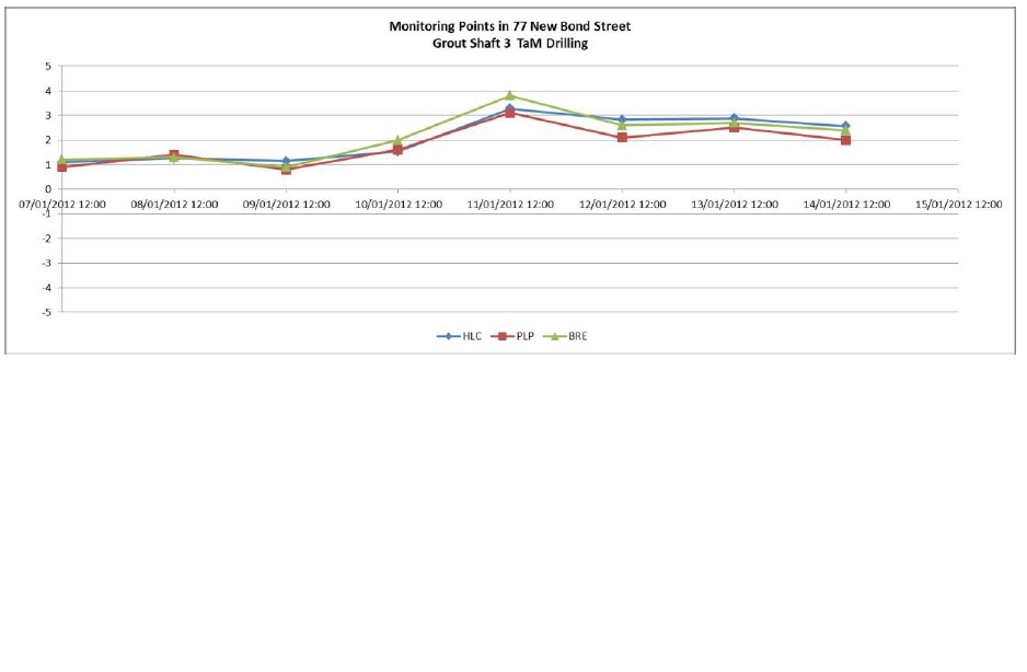
Figure 14: Evidence of heave picked up on the hydrostatic levelling system, BREs and PLPs, caused by the Water Flush drilling at Bond St shaft 3:
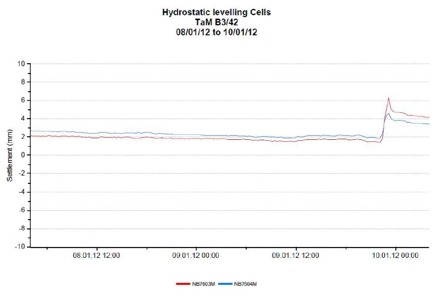
Figure 15: Evidence of heave picked up on the hydrostatic levelling system caused by the Water Flush drilling at Bond St shaft 3:
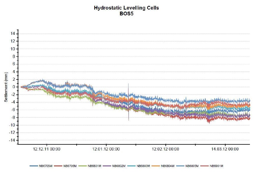
Figure 16: HLC plot showing the gradual settlement at shaft 5, caused by the dry auger drilling method.
Asset Management
Any ground movement, whether settlement or heave, has the potential to cause damage to overlying structures. Though in general, a uniform ground movement poses less risk of damage. The production of differential settlement across a building will generate tensile strain and can lead to cracking and structural damage. As previously described the sudden unpredicted and localised spikes of heave caused by the Water Flush drilling method are unfavourable, the gradual and widespread settlement that has been seen with the Auger drilling method is preferred, as differential ground movement is controlled, and the movement that does arise can easily be treated during phases of grouting, prior to the start of main construction activities.
Safety considerations
The spoil produced by the water flush drilling system consists of a slurry mix of clay and bentonite that requires special equipment for its management and treatment before it can be taken away from site and disposed.
The water flush method uses special flushing pumps with the capabilities of producing high flows at low pressures (necessary to minimise ground heave) and also pumps with the suction capacities to pump the thick slurry mix from the bottom of the shaft to the recycling tanks at ground level. These items of plant are of a considerable size and take up vital room on a site of a very restricted size.
The slurry requires settling and filtering at surface level by means of settlements tanks and a series of filters to eliminate the suspended particles in the mix before it can be returned into the water flush system and reused for drilling. This treatment is necessary because the particles have the potential for damaging and blocking the pipes and pumps of the flushing system causing plant breakdown with the consequent downtime.
With time, the settlement tanks and filters clog up and the recycling system is not capable of filtering the particles from the drilling slurry which thickens up affecting its properties, making the water flush system less efficient. Therefore, maintenance of the settlement tanks and filters is needed on a regular basis, during which activities drilling may need to stop temporarily. The solid materials captured by the filters which settle at the bottom of the settlement tanks are taken away from site by means of gully sucker type lorries on a regular basis, which can add to the pollution and noise generated.
The work force is constantly exposed and is in contact with water when using the water flush method, hence specialised protective water proof clothing is required at all times. This water also has the potential to introduce slippery, wet and frozen surfaces that present a constant hazard to the workforce.
The drilling spoil generated by the auger method is found to be easier to manage due to the dry and solid nature of the clay material withdrawn during the drilling of the boreholes. This dry material is easily handled inside the very restricted space available in the shafts without the necessity of special equipment and is lifted to ground level from where it is easily taken away from the site in lorries.
This solid clay material is free of contaminants and does not require any special chemical treatment which makes it environmentally friendly as the clay can be disposed of and recycled straightaway with no need to store it on site. The traffic requirements for lorries and wagons in order to remove spoil, is minimal with the auger method.
Only standard protective cloths are required to work with this dry spoil and the slips, falls and trip hazards are largely eliminated as the plant and equipment to drill with this method is drastically reduced making the site less congested and easier to maintain.
7. Conclusion
The choice of method for drilling holes for TaM installation in London Clay is dependent on a number of factors; from the depth of drilling and the nature of overlying structures, to the site constraints imposed and the time scale available.
The depth of drilling, the nature of overlying structures, the imposed site constraints and the time scale available are some of the factors to be taken into account when choosing with TaM installation method to use in London Clay.
Following the initial trial, that included drilling with the Water Flush method and the Dry Auger method from the first two grout shafts, the decision was made to progress drilling from the remaining 11 grout shafts using the Dry Auger method.
Limited site constraints, including small diameter shafts and adjacent contracts meant that the utilisation of space and reduced amount of plant required by the Dry Auger method gave it a clear advantage, increasing the free space on site and reducing the number of breakdowns and maintenance required on the plant.
Another clear advantage is the nature of the drill arising’s. Dry inert clay is easily removed and disposed of or even recycled, whereas the wet flush method produces a clay slurry which requires significant on site treatment, regular slurry tankers and large volumes of water, increasing health and safety risks on site and increasing the environmental impact.
Given the period of time that grouting operations will need to be active for, and the desire to limit damage to overlying structures, the Dry Auger method also allows for careful control of ground movement. Generating no heave, only gradual settlements which are effectively controlled through phases of grouting. The wet flush method has shown to induce sudden uncontrolled heave, posing possible damage to overlying buildings and utilities.
All of these factors, i.e. easier spoil handling/removal, favoured and controlled ground movements, and less congested sites meant that there were less delays and downtime with the Dry Auger method, overall helping to maintain production rates, ensuring that the TaM installation process would not delay main construction activities.
Though the Dry Auger method has shown to be favoured here. It is highly dependent on the site conditions and should not be taken as a general assumption. On-site trials would be required to determine the preferred method to suit differing locations, geology and constraints.
8. References
O’Reilly, M.P. and New, B.M. (1982). Settlements above tunnels in the United Kingdom – Their magnitudes and prediction, Tunnelling’82, pp. 179-181
Mair, R.J., Taylor, R.N. and Bracegirdle, A. (1993).Subsurface settlement profiles above tunnels in
clays, Geotechnique 43, No. 2, pp. 315-320
Crossrail Civil Engineering Design Standards (Part 7 and 8)Acronyms Used:
TaM – Tube- à- Manchettes
SCL – Sprayed Concrete Lining
TBM – Tunnel Boring Machine
I&M – Instrumentation and Monitoring
HLC – Hydrostatic Levelling Cell -
Authors

P Pérez Lupi MSc - BAM Ferrovial Kier
Bam Ferrovial Kier JV
E Lewis MEng - Crossrail Ltd
Crossrail
J Adetoye BEng - BAM Ferrovial Kier
Bam Ferrovial Kier JV
X Gonzalez TEd - Keller Bam Ritchies
Keller Bam Ritchies
N Gallego Ramirez MSc - BAM Ferrovial Kier
Bam Ferrovial Keir JV
Z Munn BEng - Keller Getec ITMSoil JV
Keller Getec ITMSoil
D Campos MSc - BAM Ferrovial Kier
Bam Ferrovial Kier JV


