Comparison Between Sprayed and Cast In-Situ Concrete Secondary Linings at Bond Street and Farringdon Stations
Document
type: Technical Paper
Author:
Edward Batty MEng, Nathan Bond MEng, Eleanor Kentish MEng, Alan Skarda MA MEng CEng MICE, Simon Webber MEng ACGI, ICE Publishing
Publication
Date: 31/08/2016
-
Read the full document
Introduction
It is well established that sprayed concrete offers a fast and effective method to seal the face of an excavation. In a relatively short space of time, sprayed concrete can be applied to an open face to support the short term ground loading on the tunnels during construction. Advances in sprayed concrete lining (SCL) technology — such as the use of wet mix processes, improved accelerators, fibre reinforcement, remotely controlled spraying robots, innovative surveying equipment and nozzleman competency schemes — have greatly increased the speed and safety of tunnel excavations using this technique. As a result, design engineers have become increasingly confident to use SCL primary linings as part of the permanent structural lining. [1]
Historically, long term ground and water pressure loads have been considered to be carried by the main structural or secondary lining, constructed using cast in situ concrete.[2] However, the advances described above have made sprayed secondary linings a viable option, which has already been proven on the A3 Hindhead Tunnel[3].
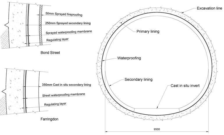
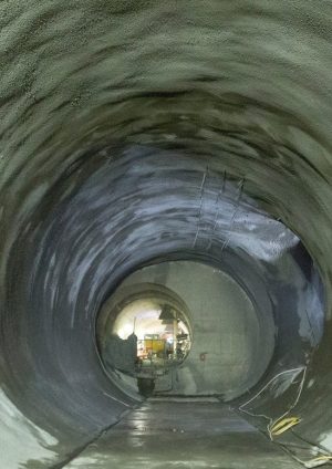
Figure 1 – Typical cross section of the platform tunnels at Bond Street and Farringdon Stations Sprayed concrete secondary linings offer potentially significant savings in cost and time during the construction process. The contractor does not need to procure a bespoke formwork system for each different sized tunnel — the SCL plant required is already on site for the primary lining. Each bay is sprayed with accelerated concrete becoming self-supporting almost immediately — compared to moving and resetting the shutter, pumping concrete and waiting for it to cure. With sprayed concrete working sequences and cross sections can easily be changed.
However, do these perceived increases in speed and reduction in cost translate into reality? This paper discusses these possibilities by comparing the waterproofing and secondary lining systems at Bond Street and Farringdon Crossrail Stations (Figure 1), which utilise sprayed and cast in situ secondary linings respectively for identically sized tunnels at similar depths.
Bond Street Station
Bond Street Station is located in Mayfair, central London, and features two ticket halls on Davies Street and Hanover Square (Figure 2). The station comprises approximately 1 km of SCL tunnels, ranging from 4–10 m in diameter.
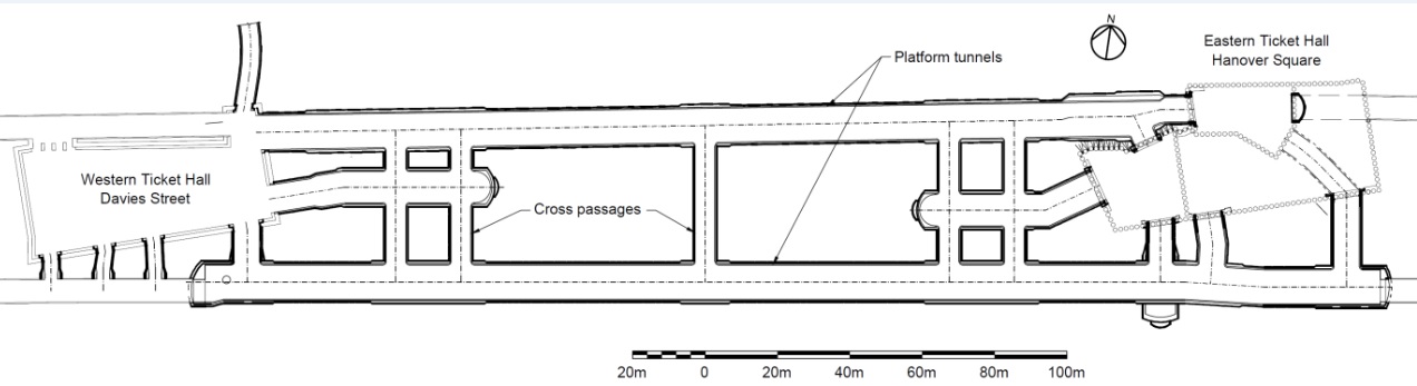
Figure 2 – Plan of Bond Street Station Design
The SCL tunnels at Bond Street were excavated entirely within the London Clay formation (A2 and A3 units), which is a stiff, low permeability clay. It was expected that this clay cover would substantially prevent the ingress of water from the upper and lower aquifers in the ground, so a sprayed waterproofing membrane was specified. Sprayed membranes have the potential to save cost and time over sheet membranes, although they typically require a dry substrate to fully cure and harden. An EVA polymer based elastic membrane was selected for this purpose, which bonds to both the substrate and secondary lining — so provides the potential for a fully composite shell, although the Crossrail design did not rely on this bond.[1][2]
The invert of the secondary lining was formed from cast in situ concrete containing both steel and poly fibres. The inclusion of poly fibres (micro synthetic monofilament polypropylene fibres) has been shown to eliminate or significantly reduce the depth of spalling in concrete exposed to fire.[5] The sprayed secondary lining contained either steel fibre or bar reinforcement, the latter around junctions.
As far as the structural design of the lining is concerned, a single layer of secondary lining with both poly fibres and steel fibres would be sufficient for both the load carrying and fire resistance requirements. However, unlike cast in situ concrete, wherever steel fibres are included in sprayed concrete mixes a number of fibres remain protruding out of the surface, which present a hazard. For this reason, a final regulating layer was included in the design, fulfilling the dual purpose of covering these steel fibres and providing the requisite passive fire protection.
The fireproofing had a similar mix design to the secondary lining, except that it contained poly fibres instead of steel fibres. While the fireproofing contributes to the structural capacity of the lining, it does not have the same level of residual flexural strength as the steel fibre reinforced layers and may be completely lost in a fire event. In this case, the residual capacity of the lining is still sufficient to resist the applied ground loads with a reduced factor of safety.
Construction
Following the completion of the primary lining, a number of preparatory works were required. This included thorough survey checks to ensure there was sufficient space to accommodate the subsequent layers of the tunnel; sealing of any leaks with an injectable hydro-reactive polyurethane grout; and covering protruding steel fibres with a 40 mm thick regulating layer.
Waterproofing Membrane
The waterproofing membrane was applied using a dry rotor pump feeding the boom of a robotic manipulator or hand spray nozzle. The membrane was generally sprayed in two consecutive layers, totalling a minimum 3 mm thickness, first to the crown and then the invert. In the junctions, double thickness was required to provide improved crack bridging performance in these areas (Figure 3).
In highly stressed areas of the tunnel (typically around junctions), the sprayed secondary lining comprised steel reinforcement of up to 16 mm in diameter. The reinforcement was hung from glass fibre reinforced polymer (GFRP) dowels, which were drilled and fixed into the primary lining before applying the membrane. Installing the dowels after the waterproofing had been sprayed proved to be problematic, as a suitable lap of the membrane up the dowel was required to be painted by hand.
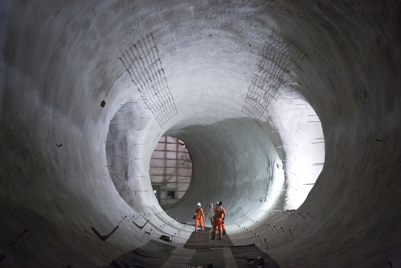
Figure 3 – A completed sprayed waterproofing membrane Once sprayed, curing of the membrane typically took 24–48 hours. However, in areas of the tunnel where leak sealing of the primary lining was less effective, the time required to achieve a compliant membrane was significantly longer.
Cast Invert
Following adequate curing of the membrane, construction of the cast invert began using a formwork system of timber and ply. The membrane was found to be delicate and was frequently damaged throughout this activity despite the best endeavours of the site team.
Following tests confirming the quality of the membrane, the tunnel invert was poured using a series of concrete lines. The length of each pour was dependent on the area of conforming waterproofing in place and typically ranged from 10–50 m.
Sprayed Secondary (SFR) Lining
Once the cast invert had reached sufficient strength for plant movement, application of the secondary SFR layer could begin. As Figure 4 shows, construction of the SFR layer followed a two-step procedure to reduce the chance of a fallout causing damage to the waterproofing membrane. Where the design included two layers of bar reinforcement, the far face and near face were sprayed in two separate layers.
The SFR mix was applied using robotic manipulators serviced by a series of pipes or remixer wagons. The lining was sprayed in bays of 2 m or 3 m in length with a maximum pump rate of 13 m³ per hour (limited to improve quality and risk of fallouts). Following the completion of each bay, curing of the lining was carried at set intervals over a 24 hour period (Figure 5).
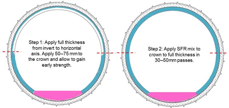
Figure 4 – Diagram showing two-step spraying procedure 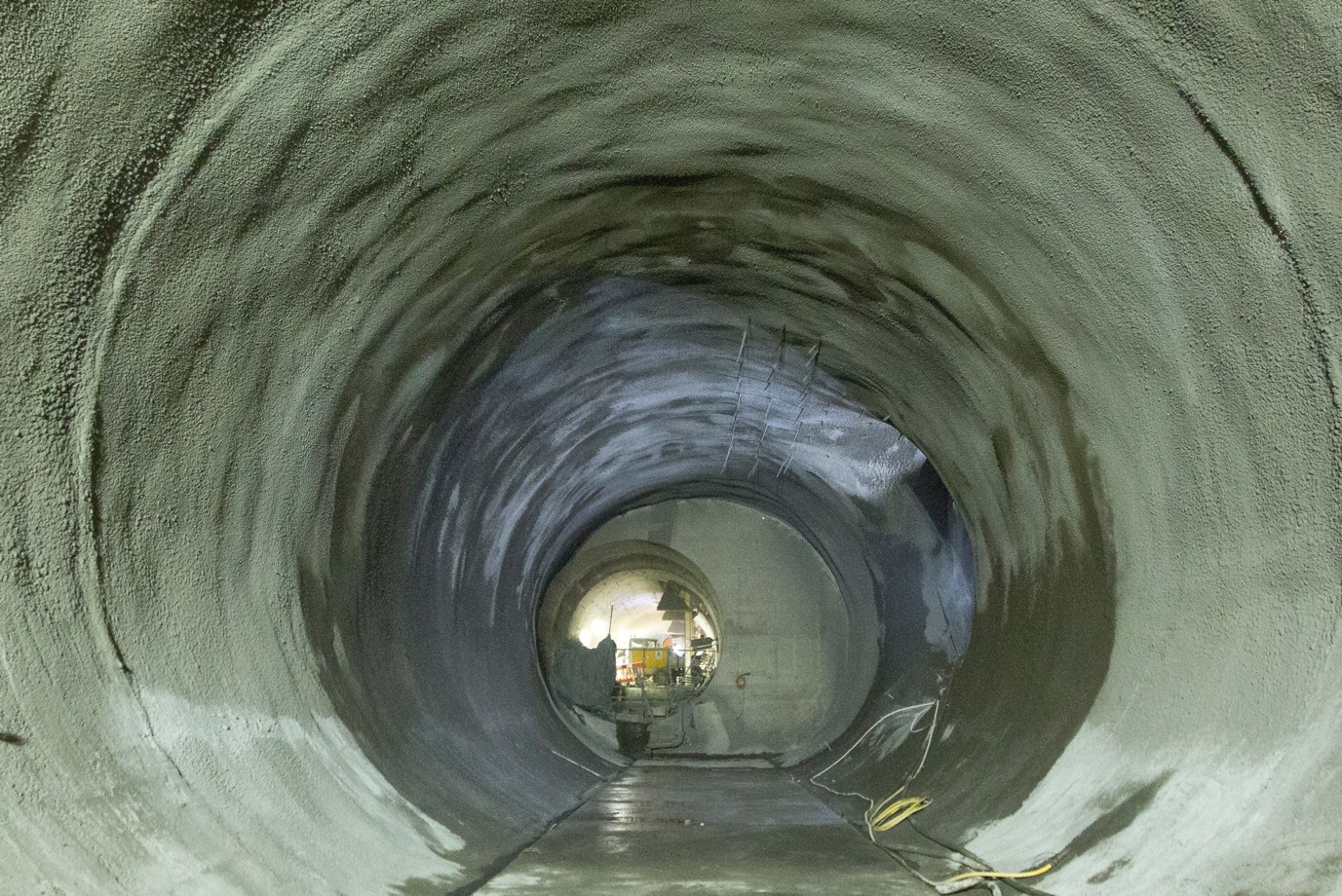
Figure 5 – Secondary lining following curing Fireproofing layer
Prior to advancing onto the next construction activity, further survey checks were undertaken to ensure adequate tolerance remained to accommodate the final 50 mm fireproofing layer.
At this stage in the works the remaining construction tolerance presented a challenge; any tight areas identified had to be milled back using a roadheader. After ensuring the minimum required fireproofing thickness could be met, the layer was applied using an automatic spraying robot able to apply a uniform thickness to the tunnel profile. The fireproofing layer was sprayed at a rate of 10.3 m³ per hour in bays of maximum 2 m in length.
Work Study
Overall 943 m of tunnel (of varying diameter), with a total surface area of 27,739 m2, was completely secondary lined in 339 days. The average production rate for the entire station was therefore 2.8 m or 82 m2 per day.
The averages in Table 1 are based on actual production rates for the platform tunnels only and do not include preparation of the primary or secondary linings (e.g. scanning, milling, etc). These preparatory activities are captured within the average production rates above for the entire station. For the sake of a fair comparison, the operatives listed are only those in the specific work gangs and do not include supervisors, general and surface operatives, banksmen, fitters, electricians and office support, as these members of the workforce can be associated with multiple tasks and would also be required for cast secondary linings. All trades were working 24 hours per day, 7 days per week.
Table 1 – Sprayed secondary lining production rates — platform tunnel
Activity Average
[m / day]
Weighted Average [m / day] Gang Man hours per m Waterproofing Invert 14.7 5.4 Nozzleman
Pumpman
General operative
Engineer
(4)17.7 Crown 8.6 Secondary Lining SFR Secondary 10.8 4.1 Nozzleman
Backup man
Pumpman
Underground plant operator
General operative
Engineer
(6)34.9 Fireproofing 6.7 Mobilisation
There was no significant time associated with the mobilisation of the sprayed secondary lining works. The majority of plant and personnel required were also involved in the primary lining process. This enabled a smooth transition between the two activities.
Farringdon Station
Farringdon Station is located in Islington, central London, and features a western and eastern ticket hall (Figure 2). The station also comprises approximately 1 km of SCL tunnels, ranging from 4–10 m in diameter.
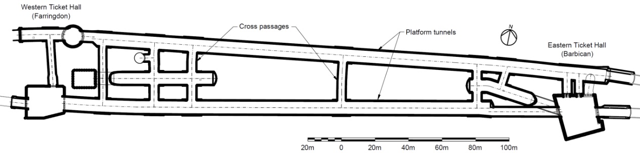
Figure 6 – Plan of Farringdon Station Design
The SCL tunnels at Farringdon were excavated within the Lambeth Group and Thanet Sands, which are highly variable strata. There is significant faulting in the area, which further complicated the geology. Within the Lambeth Group, ground investigations identified sand lenses containing high pore water pressures. There was a risk that the water in these lenses would seep through the primary lining, making it too wet to allow sprayed waterproofing membranes (specified on all other Crossrail stations) to cure. Sheet waterproofing membrane was therefore specified, with a cast in situ secondary lining preferred to spraying onto sheet.
Waterproofing was provided by a 2 mm thick PVC membrane covering the entire surface area. Additionally, a system of PVC water barriers and re-injectable grout hoses were located at each joint. The membrane is not bonded to the surrounding concrete so allows lateral transmission of water. The addition of water barriers was made to compartmentalise the lining, so that if leaks occur the surrounding grout tubes can be injected (Figure 7).
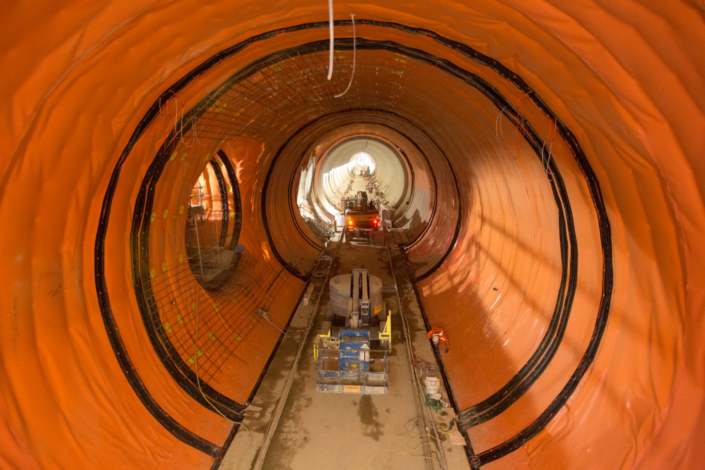
Figure 7 – Completed sheet membrane showing waterbar at construction joints The lining is designed as a dual shell, meaning there is no bond or transfer of shear between the primary and secondary linings due to the presence of the sheet membrane. The secondary lining was cast monolithically with C50/60 concrete, and included both steel and poly fibres. The polypropylene fibres were dosed at 2 kg/m³ to fireproof the concrete, to resist the EUREKA fire curve, a requirement of the Crossrail specification.
Construction
Following the completion of a significant proportion of the primary lining, preparatory works for the secondary lining began with sealing cracks greater than 1 mm, due to the expectation of corrosive ground water. Following treatment, a regulating layer was applied to cover steel fibres protruding from the primary lining.
Waterproofing Membrane
Sheet membrane was applied in two stages to suit the construction methodology (Figure 8). The first stage involved laying the membrane on top of a geotextile layer in the invert. To avoid damage to the membrane, a 1.5 mm thick protection sheet was placed on top prior to installing the invert formwork.
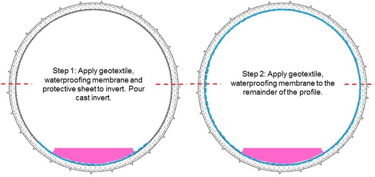
Figure 8 – Diagram showing sheet membrane waterproofing sequence The invert was cast using steel road forms fixed into the primary lining of the tunnel to form a perpendicular joint. The road forms sat within the waterbar in order to form the construction joint between the waterbar fins. Invert bays were typically 24 m in length.
Once a suitable length of invert was cast, a waterproofing gantry was erected to place the membrane. This waterproofing gantry travelled on the cast invert to allow the waterproofing installers access to the full profile of the tunnel lining. Prior to moving on to the next stage of construction, welds between membrane sheets were double seam welded and air pressure tested. In addition waterbars, repairs and patch repairs were single welded and hook tested for compliance.
Cast Secondary Lining
The secondary lining was cast using a bespoke travelling shutter system. While both platform tunnels were the same size, the cross passages and concourses linking the running tunnels were of different sizes. BFK therefore had to procure three travelling shutters: one for the platforms, one for the concourses and a transformable cross passage shutter which could change profile for each cross passage. Collar pieces were also needed at junctions in order to cast architectural chamfers.
In order to begin construction of the travelling shutter, 50 m of invert needed to be completed, reach sufficient strength and be clear of obstructions. An 11.9 m length shutter was procured based on the maximum bay length specified by the designer.
The shutter was serviced by a pump supplied with concrete by remixer wagons, which pumped directly into the formwork via ports. Although the shutter was designed for a maximum rate of rise, in reality the concrete supply was the limiting factor and the pour rate was typically 17m³/hour, which equated to 1.6 m per hour as a rate of rise. Each 11.9 m bay (135 m3 concrete) could thus be poured in 8 hours. Observation windows were used to monitor the height of the concrete and measure the rate of rise. Clamshell vibrators, spaced regularly on the skin of the shutter, were used to compact the concrete.
To improve the turnaround time of the shutter, the form was not anchored into the invert. Vertical movements were resisted by uplift restraints attached to the trelliswork; horizontal movements were controlled by the pour sequence, limiting the maximum height difference to 500 mm each side. The site engineer monitored any movements throughout the pour.
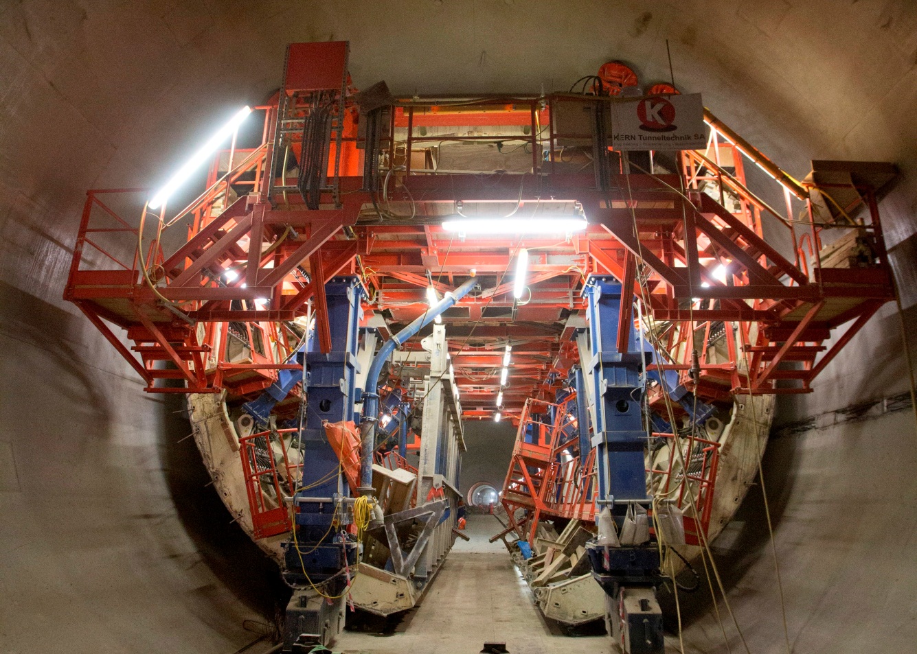
Figure 9 – The shutter in action Work Study
A length of 929 m of tunnels (with varying diameters) equating to a total surface area of 29,973 m2 was completely secondary lined in 395 days. The average production rate for the entire station was therefore 2.4 m or 75.9 m2 per day.
The rates in Table 2 are based on actual production, for the platform tunnel, and do not include preparation of the primary lining, mobilisation or shutter design/manufacture/delivery periods. These preparatory activities are captured in the overall production rates above for the entire station. For the sake of fair comparison, the operatives listed are those in the specific work gangs and do not include supervisors, general and surface operatives, banksmen, fitters, electricians and office support as these members of the workforce can be associated with multiple tasks. Waterproofing installers were working 8 hours per day, 5 days per week. All other trades were working 24 hours per day, 7 days per week.
Table 2 – Cast in situ secondary lining production rates — platform tunnel
Activity Average [m / day] Gang Man hours per m Waterproofing Invert + Crown 9.7 Waterproofing operatives (10) 8.2 Secondary Lining Cast Crown 6.0 1 Pumpman
4 Underground plant operators
2 Carpenters
Engineer
(8)32.0 Mobilisation
There was significant mobilisation required for both the sheet membrane and travelling shutter works. Waterproofing scaffolds were erected once sufficient space was available; each scaffold typically took four days to construct and was done in advance of the waterproofing operatives’ arrival to each section of works.
The travelling shutter system required 3–4 months lead time for design and fabrication. The erection and mobilisation period for the travelling shutter was 10 weeks, which happened concurrently with primary lining and waterproofing works further along the tunnels.
Discussion
The following subsections discuss the key results of the platform tunnel work studies (refer to Tables 1 and 2), as well as the advantages and disadvantages of each method of secondary lining construction.
Mobilisation and Logistics
As discussed above, the travelling shutter required 3–4 months lead time and 10 weeks for mobilisation on site. While much of this could be undertaken off the critical path, in order to move the shutter to another tunnel it had to be dismantled and re-erected. This required a further 4 weeks, during which no casting could take place.
Conversely, the plant and labour required for sprayed secondary linings were already on site from the excavation and primary lining stages. If a new spraying robot was required, this could typically be hired within a week. Spraying plant can usually simply drive to different tunnels, allowing greater flexibility in working sequences. Although the rebound produced from the spraying process used more concrete, this proved to be useful for creating temporary ramps to access different areas of the tunnels.
Mobilisation periods for waterproofing plant, equipment and labour — while slightly longer for sheet membranes due to the requirement to erect a rolling scaffold — were not significant.
Platform Tunnel Production Rates
Waterproofing
Based on Bond Street and Farringdon Stations, the work studies show that sheet membrane was both faster (9.7 m/day) and used fewer man hours (8.2 man hours/m) than sprayed waterproofing (5.4 m/day and 17.7 man hours/m respectively). The reason for the slower progress of the latter can be attributed to the presence of ground water seeping through the primary lining. This had to be completely sealed before spraying could commence, which was often a time-consuming process. Furthermore, the sprayed waterproofing membrane proved to be fragile and, despite the best endeavours of the team, was frequently damaged, again slowing progress of the works.
Although ground water was not anticipated at the design stage (due to the location of the Bond Street tunnels within an impermeable clay), sprayed waterproofing is most effective in a dry tunnel and hence carries an inherent programme risk if unexpected ground water is encountered.
On the other hand, installation of the sheet membrane at Farringdon required little rework, and the quality of the waterproofing system was rarely affected by the presence of water in the tunnel. The protective sheet in the invert was effective at preventing damage and, once installed, sheet membrane could be cast against almost immediately.
Secondary Lining
The work studies suggest that, once the required mobilisation had taken place, the cast methodology at Farringdon provided a higher overall production rate (6.0 m/day) compared with the sprayed option at Bond Street (4.1 m/day). The man hours required to construct 1 m of platform tunnel were similar, 32.0 compared to 34.9 man hours/m respectively.
While the sprayed secondary lining involved a similar process to the primary lining, the need to spray two layers (SFR plus fireproofing) slowed the overall progress of the works. Furthermore, limited construction tolerances, the requirement to provide a minimum SFR thickness and technical challenges associated with the application of the 50mm thick fireproofing layer further reduced production rates at Bond Street. The monolithic cast in situ approach at Farringdon provided a higher and more consistent overall production rate, which was rarely affected by rework of the lining.
Summary
Combining the insights of the mobilisation and production rates, sprayed secondary linings are more suited to a number of shorter lengths of tunnel, with more cross passages and different cross sections. Cast secondary linings are more suited to long, straight lengths of tunnel with fewer bends, inclines, junctions or changes in cross section, although the design of such tunnels could be optimised for a cast secondary lining.
Conclusions
The recent trend in the UK industry towards the design and construction of sprayed secondary linings is fuelled by potential gains in cost and time. However, the work studies undertaken at Bond Street and Farringdon Stations, for the platform tunnels, demonstrate that these potential gains do not always translate into reality.
The waterproofing production rates were considerably higher for the sheet membrane at Farringdon, due to the presence of ground water at Bond Street which required considerable time to seal before sprayed waterproofing could be applied effectively.
The sprayed concrete secondary lining at Bond Street Station provided reduced mobilisation periods and a greater flexibility over the sequencing of the works. Nonetheless, these benefits had little impact on achieved production rates as technical challenges presented throughout the construction affected the programme. Through future developments in design, materials and equipment, these technical challenges may be overcome and the continuing development of new technologies will aid the construction of the sprayed concrete secondary linings for permanent works.
At Farringdon Station the cast in situ lining required careful planning in order to streamline the construction throughout the project. The use of this established method presented few challenges and consistent production rates were maintained throughout the construction.
The future success of sprayed secondary linings will be dependent on the incorporation of the lessons learnt from this and other similar projects.
References
[1] J. Su and A. Thomas (2014). Design of Sprayed Concrete Linings in Soft Ground — A Crossrail Perspective. Crossrail Project: Infrastructure design and construction. ICE Publishing.
[2] A. Pickett (2014). Crossrail Sprayed Concrete Linings. Crossrail Project: Infrastructure design and construction. ICE Publishing.
[3] P. Arnold (2012). Going under the Devil’s Punch Bowl: the story of the A3 Hindhead tunnel, UK. Proc. ICE — Civil Engineering 165 (CE4) 162–170.
[4] P. Evans, J. Turzynski, R. Oag and A. Sindle (2011). Super subterranean hub: updating King’s Cross St Pancras. Proc. ICE — Civil Engineering 164(2) 73–80.
[5] C.G. Bailey and G.A. Khoury (2011). Performance of Concrete Structures in Fire. The Concrete Centre.
[6] K. Smith (2015). Waterproofing — the best of all worlds? Tunnelling Journal.
-
Authors

