Compensation Grouting
Document
type: Technical Paper
Author:
Owen Frances, R Hayman-Joyce
Publication
Date: 10/11/2015
-
Read the full document
1 Introduction
Compensation grouting was specified as one of the settlement mitigation measures to be used on Crossrail. The last time this technique was used to this scale was during the extension of the Jubilee Line in the 1990s.
The Crossrail scheme is split into a number of specific contracts. The focus of this paper is contract C300 – The Western Running Tunnels from Paddington to Farringdon and C410 – The station caverns at Bond Street and Tottenham Court Road. The Main Contractor for both of these contracts was the BAM Ferrovial Kier (BFK) joint venture. The compensation grouting sub-contractor was a second joint venture of Keller and BAM Ritchies (KBR). A key element in any compensation grouting project is the information gathered by the instrumentation and monitoring. In this case, this formed a separate, significant sub-contract in itself and was not part of our scope of works.
Although BFK had split the compensation grouting and monitoring into two separate packages, we worked together as one team. Had the two packages been awarded to competing organisations, this relationship may not have been so seamless.
2 Site layout
On this contract, the compensation grouting was carried out from shafts specifically constructed for the purpose. The grout shafts had an internal diameter of 4.5m at the working height, but due to the congested nature of services in central London, some of the shafts had a reduced opening toward the surface. There were a total of 13№ grout shafts over the project, 5№ at Bond Street, 7№ at Tottenham Court Road and a single shaft at Fisher Street where a ventilation shaft is located. Finding suitable locations for the grout shafts was not an easy task to begin with, as each location had to satisfy all of the following criteria:
- Enable full coverage of the required area for compensation grouting treatment.
- Allow any services to be suitably diverted.
- Include a working area for the compensation grouting operations.
On completion of the works, the grout shafts will be backfilled and the ground reinstated but they need to remain operational for a number of years. During this time, the re-development of nearby buildings also needed to be considered. Every effort was made to minimise the disruption to the public, including the locating of one of the grout shafts within an existing disused tramway tunnel.
The tender information included detailed information on the available space around each grout shaft. Although this did prove to be accurate, it still had a significant impact on our works. Given the limited space available at each shaft, a compound area at each station would have been beneficial.
During the works, we were made aware of agreements between CRL and other stakeholders, such as granting access over a working grout shaft and interactions with other contractors. The relatively short notice of these changes caused delay and disruption to our works.
3 Drilling
The compensation grouting system consisted of a number of arrays of Tube à Manchette (TàM) pipes which were drilled radially from each of the grout shafts. TàM pipes consist of tubes with ports at regular (in this case 0.5m) intervals, covered by a rubber sleeve which acts as a one way valve. Combining this with a double packer (a pair of inflatable seals) allows grout to be injected at very specific locations in the ground.
Some of the TàM pipes installed extended over 100m from the grout shafts, although there was a significant reduction in accuracy and production rate when compared to lengths of up to 60m. The layout of the TàM arrays was governed by a number of factors:
- The outer boundary of the treatment area had to meet with the client’s requirements.
- The length of individual TàM was kept to a minimum.
- The plan spacing at the distal end of the TàM was limited to a maximum of 3m (4m including deviation). This proved to be a suitable limiting criterion in the ground conditions and tunnel depths of this project.
- The plan spacing at the proximal end of the TàM, on the inner face of the grout shaft, had a minimum limit in order to maintain the structural integrity of the shaft.
- The maximum elevation of each TàM had to be such that there was a minimum of 2m cover of London Clay over the working length of the TàM.
- The minimum elevation of each TàM had to be such that it was outside of the grouting exclusion zone of the tunnel.
- There were limitations on the vertical spacing of the holes through the shaft lining.
- Practical matters such as positioning boundaries between shaft arrays along road centrelines or outside building footprints.
- Where possible, distributing the total area equally between each of the grout shafts.
- Programme considerations such as assigning a particular section of tunnel to a particular shaft.
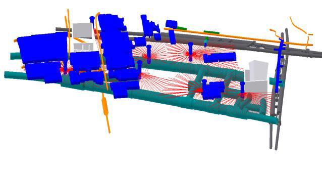
Three dimensional modelling was used to design all of the TàM arrays, ensuring that all of the above criteria were met. Drilling and installation schedules were produced directly from the three dimensional model. A view of Tottenham Court Road station can be seen in Figure 1.

Figure 1. Three dimensional view of Tottenham Court Road Station
The detailed design of the TàM arrays was required relatively early in the contract. At this time, the information provided “for construction” was only 2D drawings. We found it difficult to obtain 3D models and these were only issued “for information” as they often contained inconsistencies. Important information such as the location of obstructions and the profile of the London Clay surface were detailed on other drawings, but not included in the 3D models we were provided with.
At the beginning of the project, two different methods of drilling were trialled:
- Water Flush
- Auger
Having completed one grout shaft with each method, it was decided to progress with the auger method. Although this did generate some settlement, it required less equipment at the surface and involved more pleasant working conditions for the operatives in the shaft.
Table 1. Summary of TàM arrays installed
Location Holes [Nr] Total Length [m] Bond Street Station 398 20,035 Tottenham Court Road 480 22,870 Fisher Street Shaft 65 2,333 Total 943 45,238 Once installed, every TàM pipe was surveyed along its full length, giving an accurate three dimensional as-built path of each individual installation.
The tender information included an outline design for the TàM arrays. This proved to be generally similar to our final detailed design. We were required to include an allowance of 20% for re-drilling out of tolerance TàM installations. In reality, we found 10% to be sufficient.
The drill rigs were customised to work within the 4.5m diameter grout shafts. The space required for break out jaws and the drilling head reduced the length of the drill string segments to 1.0m. Increasing the diameter of the shaft would increase the production rate by reducing the frequency of rod changes.
4 Pre-treatment grouting
This phase of grouting was essentially the commissioning of the system. The process was deemed to be complete when heave of between 3 and 5mm had been generated over the whole area of the grouting arrays. The activity of installing the TàM pipes did in itself cause some settlement, but this was more than compensated for during the pre-treatment grouting phase.
As this was the first activity which intended to cause changes to the ground level, it was done gradually over a number of passes. Each grout pass generated approximately 0.5mm of heave. This gradual approach provided the client and asset owners with confidence in our ability to control the ground profile to a high degree of accuracy.
During this phase of the works, the Grout Efficiency Factor (GEF) was measured. This is a measure of the heave generated per unit volume of grout injected and the loss of grout into the surrounding ground (without generating heave).The completion of the pre-treatment is often linked to Key Dates under the terms of the contract as the area is then ready to react to any settlements that may occur as a result of the planned excavations.
A low strength grout was used to facilitate repeat injections. The grout mix had a water:cement ratio of 2.0 and a nominal quantity of Bentonite in order to limit the bleed. Whilst we appreciate the requirement for quality control by viscosity and density testing, the benefit of expensive Modulus of Elasticity tests was not understood.
Although the GEF varied around the site and changed with time, a value of 0.4 was generally observed.5 Concurrent grouting
As the name suggests, this is where grouting is carried out concurrently with excavation activities and forms the bulk of our works. The excavation activities fell into three categories:
- Station Box Excavation
- Tunnel Boring Machine
- Spray Concrete Lined
The settlement generated by each of these techniques was dealt with in a different way.
5.1 Station Box Excavation
The layouts of the Crossrail stations generally include a large box at either end of the station. The perimeters of the boxes were formed using secant piles or diaphragm walls. The inside of the boxes were then excavated form the top down with props installed as the excavation progressed. Although settlement was observed in the surrounding area and deflections were monitored in the walls and props of the excavation, they were not significant enough to warrant compensation grouting to be carried out continuously. We were able to monitor the settlement and prepare reactive grouting proposals – more akin to grout jacking than concurrent grouting.
5.2 Tunnel Boring Machine
Two earth pressure balanced Tunnel Boring Machines (TBMs), Phyllis and Ada were used to form the 6.9km long tunnels from Westbourne Park to Farringdon. Compensation grouting facilities were not required along the entire length of the tunnel as the passing of a TBM alone does not generally cause sufficient settlement to require compensation grouting as a mitigation measure. At the location of the stations, however, the cumulative settlement caused by all the excavation activities warranted the installation of the grouting scheme and hence it was prudent to use the installed system to manage the settlement, regardless of cause, for the duration of the contract.
By the time the TBMs arrived at the first compensation grouting array, it had already tunnelled a considerable distance. This gave ample opportunity to measure the actual settlement caused by the passage of the TBM without the use of compensation grouting. The results of the monitoring demonstrated that the magnitude of the settlement was well within the allowable limits.
When planning the resource levels on site, one of the scenarios with the potential to create a peak demand was the passage of the TBM at its maximum rate of excavation and on the maximum allowable limit of volume loss (leading to settlement). The low volume loss observed from the TBM passage and the grout efficiency factor observed during the pre-treatment, allowed for the preparation of compensation grouting passes which maintained the ground level within acceptable limits, did not hinder the progress of the TBM and could be carried out from the existing grout shafts and surrounding compounds.
5.3 Spray Concrete Lined
The station caverns and a number of connecting passages were all formed using Spray Concrete Lined (SCL) excavation techniques. The TBM excavated running tunnels were enlarged to form platform tunnels using SCL techniques. The high concentration of excavation in the vicinity of the new stations made this the largest contributor to surface settlement and thus the bulk of the compensation grouting was focused on the SCL excavation.
In order to maintain the best possible control of the surface levels, each small advance of SCL excavation was accompanied by a concurrent grouting pass. The grout passes were each designed individually to compensate for the predicted settlement caused by the accompanying excavation advance. The site teams responsible for each of these activities were in constant communication with each other, to ensure that the two activities remained concurrent. This was important as it affected not only the settlement profile but the safety of the underground operations.
6 Grout jacking
Whilst the grout passes for concurrent grouting are proactive and designed on the basis of predicted settlements, grout jacking passes are reactive and are designed in response to observed settlements. The results from an assortment of monitoring systems were used to produce surface contour plots. These were commonly used to define the limits and intensity of a grout jacking pass. The mechanism is similar to the pre-treatment phase in that heave is generated in increments of approximately 0.5mm.
If a significant amount of grout jacking was required following a concurrent grouting pass, this information was fed back so that the intensity of the concurrent grouting passes could be increased, leading to a more effective balance of settlement and heave.
In some cases, it was not clear which specific activity had caused the settlement. There were activities being carried out by other contractors on nearby sites which had an influence on the behaviour of the ground. Having installed the compensation grouting system, our role was to respond to the settlement as it occurred, without necessarily investigating the cause of each incident.
On completion of any excavation activity in an area, grout jacking was required for up to three months as the ground continued to respond to the excavation activities.
7 Information exchange
Our aim as a grouting contractor was to carry out grouting that mitigated the settlement caused by the excavation as accurately as possible. In order to do this, we relied on a continual flow of information between ourselves, the excavation team and the monitoring team. The primary route for this information exchange was during the Shift Review Group meetings and also during the weekly Contract Technical Committee meetings where asset owners were
also invited to discuss the current activities. This system of meeting proved to be an excellent forum for exchanging information.7.1 Excavation details
The excavation team provided full details of each planned advance. This included the coordinates of the start and end point as well as the volume to be excavated, the anticipated volume loss and the programmed time for each advance to take place. At tender stage, the volume of each tunnel section was not readily available and had to be calculated from a number of 2D sections.
7.2 Grout pass design
From the excavation data supplied, the as-built location of the TàM arrays were added at this location and the specified exclusion zone calculated to ensure that the grouting did not cause increased stresses on unsupported sections of excavation.
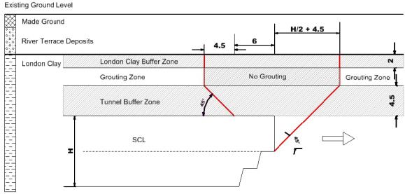
Figure 2. Grout exclusion zone for SCL tunnels
The exclusion zone shown in Figure 2 shows a minimum clearance above the crown of the tunnel, below the upper surface of the London Clay, in advance of and behind the excavation. An assessment of the anticipated zone of influence was made, which defined the outer limits of the specific grouting ports which may be used in a particular grout pass. Figure 3 shows an example excavation advance with the inner exclusion zone and the outer zone of influence along with some proposed injection locations.
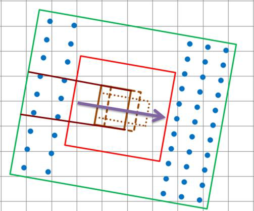
Figure 3. Example plan view of ideal injection locations in relation to a tunnel advance
From the volume of ground to be excavated, the anticipated volume loss and grout efficiency factor, a total volume of grout to be injected was calculated, to compensate for the predicted settlement. Having established the limits of the grouting and the exclusion zone, a distribution of grout was designed. This took into account the distribution between the injections carried out ahead of the excavation and those which could take place after the excavation has passed. The
cross sectional distribution of grout used a higher intensity of grouting along the excavation axis, where the settlements were predicted to be at their greatest and tapered towards the outer edges to minimise the gradient at the outskirts of
the treatment area.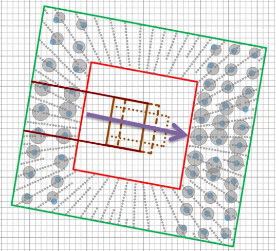
Figure 4. Example plan view of actual injection locations in relation to a tunnel advance
The final step in the process was to select actual grout ports for the injections. Figure 4 shows the same example grout pass as Figure 3, but with the as-built grout ports highlighted. Efficiencies could be gained by selecting grout ports within the same TàM pipe as this reduced the time required to place the packer at each of the required ports.
Each designed grout pass was presented in tabular and graphical format, along with the accompanying excavation information. The proposed grout passes were circulated to both technical and non-technical members of the team so the information was presented accordingly.
7.3 Injection control
The high level of control required for these grout injections required the use of a computer controlled bank of pumps known as a grout module. Once a grout pass had been approved, it was then passed on to the grout module operator for implementation. The data behind the grout pass was used to generate a paper pro-forma for the module operator as well as a data file for the module computer. Once ready, the file was loaded and each grout injection was then able to terminate automatically at the required volume, without exceeding the pressure limits set.
In addition to controlling the grout injections, the computer in the grout module also displayed the surface level monitoring in real-time. As injections were being carried out, the module operator was able to observe the effect of the injection on the ground and, if necessary, he would terminate the injection manually if he observed that an unexpected amount of heave was being generated.
7.4 Monitoring feedback
On completion of each grout pass, the actual heave generated was monitored and assessed against the settlement which occurred. From these results, an assessment was made of the effectiveness of the concurrent grouting pass and any changes made to subsequent pass designs as required. This could be a global change, a change in grout distribution or a localised factor unique to a particular part of the site.
The system which collated all the monitoring data also included the as-built TàM positions, street maps and the location of the proposed tunnels and excavations. Having all the data in a single system made it easy to correlate settlement and heave with specific grout ports. An area could even be selected on screen, which generated a list of all the grout ports within a drawn area.
8 Conclusion
The process of generating heave by grouting, to balance the settlement caused by excavation requires a continual flow of information. By working together in a collaborative way and sharing information, the process can be refined to an efficient and accurate means of mitigating settlement.
By using current technologies, we have been able to analyse, produce and share vast quantities of data. As the construction of Europe’s largest construction project continues, much of the general public remain blissfully unaware of the works going on under the feet.
-
Authors