Control Narratives for Heating Ventilation and Air Conditioning System for Stations Shafts and Portals
Document
type: Technical Paper
Author:
Wing Fung PhD MSc BSc(Eng) CEng MCIBSE, ICE Publishing
Publication
Date: 30/09/2017
-
Read the full document
Introduction
System narratives provide a functional description of the manner in which plant or systems will be controlled. A good understanding of the system narratives is important to allow development of an appropriate local and remote control regime to meet the following system operation and maintenance requirements:
- Remote monitoring and control of building services installation from maintenance depots and railway control centre. It is noted that timely detection and response to failures is becoming more and more important in modern day’s metro operation and maintenance criteria
- Critical services have to be ‘self-contained’ so that their service will not be disrupted in an event of breakdown in communication system (namely station LAN, WAN and public internet).
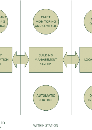
They also provide consistency for operation and maintenance of similar systems in Crossrail stations, shafts and portals. In Crossrail, a Building Management System (BMS) is used to integrate the local control of building services installations with the railway/ public communication systems. Figure 1 provides a typical system interface diagram for BMS.

Figure 1 – System interface diagram for a BMS
The design of BMS is to provide monitoring, alarm and control functionality for a wide range of Station Mechanical and Electrical equipment. The primary function of the BMS is as an operation and maintenance tool for Station building services plant and equipment, such as ventilation and cooling plant, LV distribution, lighting systems, pumping and drainage equipment. The BMS does not control or directly monitor any Life-Safety plant or equipment such as Tunnel Ventilation Fans and Dampers, Station Smoke Extract or Stair Pressurisation Systems. The BMS will provide the Station Maintainer with the facility to locally, or remotely, set-up, adjust, monitor and interrogate the operational and maintenance parameters of the Station Mechanical and Electrical building services systems. The BMS will have interfaces with the Station Fire Alarm Panel (FAP) and the SCADA system. These interfaces enable the BMS to be notified of any Fire Alarm signals and to relay selected high-level plant and equipment alarms to the Station Operations Room (SOR), Route Control Centre (RCC), Station Maintainers Remote Monitoring Facility or any other selected location, via the SCADA system.
This paper describes in the following sections, how remote control and monitoring functions are fully integrated into the system narratives for the heating ventilation and air conditioning (HVAC) system in Crossrail stations shafts and portals. The HVAC system is comprised of:
- Supply and extract air system
- Platform smoke extraction and ventilation system
- Fire fighting staircase pressurisation system
- Air release system
- Primary and secondary chilled water system
For each system, the narrative analyse the functionalities of the system in terms of motor control, control interlock, automatic control and plant remote control and monitoring. This is illustrated in Figure 2 below:
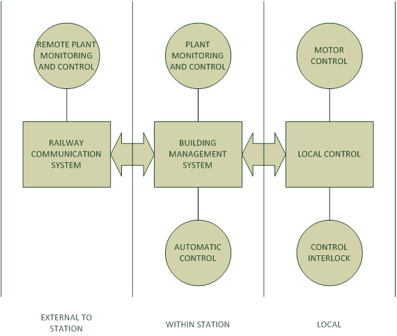
Figure 2 – Key functional blocks in a system narrative
Supply and Extract Air System
The system comprises a duty / standby pair of air handling units (AHU). As stipulated in the design, each AHU may consist of fresh air inlet modulating damper, electric heater battery, panel filters and bag filters, chilled water cooler battery, variable speed supply fan (constant volume application), supply duct motorised isolation damper, extract duct motorised isolation damper, variable speed extract fan (constant volume application). Where provided, energy reclaim devices can be in the form of thermal wheels, run-arounds coil or plate heat exchangers. Each of these devices will be provided with filters, pipes, circulation pumps, sensor and integral controller as appropriate to manage heat recovery and frost control.
A typical system configuration of supply and extract air system is shown in Figure 3.

Figure 3 – Typical system configuration of supply and extract air system
Motor Control Centre Requirements
Selector switches for each AHU will be incorporated on the fascia of the motor control cubicle (MCC).
Each fan will be provided with a Test/Off/Auto switch. ‘Test’ will allow the fan to be operated independently of the BMS providing all safety interlocks are healthy. ‘Off’ will shut down the fan. On ‘Auto’ the fan will be stopped / started at the dictates of the BMS. When the selector switch is in the auto position the control strategy as detailed under Automatic Control will apply. The switch position is monitored by the BMS. If not in auto an alarm will be raised at the BMS Operator’s Workstation.
Each heater battery will be provided with an Off/Auto switch. ‘Off’ will shut down the heater battery via hardwired and software interlocks. On ‘Auto’ the heater battery will be enabled / disabled and controlled at the dictates of the BMS. When the selector switch is in the auto position the control strategy as detailed under Automatic Control will apply. The switch position is monitored by the BMS. If not in auto an alarm will be raised at the BMS Operator’s Workstation.
Energy Reclaim Device will be provided with an Off/Auto switch. ‘Off’ will shut down the reclaim device. On ‘Auto’ the reclaim device will be enabled / disabled and controlled at the dictates of the BMS. When the selector switch is in the auto position the control strategy as detailed under Automatic Control will apply. The switch position is monitored by the BMS. If not in auto an alarm will be raised at the BMS Operator’s Workstation.
A reset pushbutton will be provided to de-latch the frost protection interlock.
Automatic Control
To start up, the BMS will determine which AHU is duty. When the duty AHU is required to operate, providing all safety interlocks are healthy and the associated switch is in Auto, the BMS will command open the supply and extract duct isolation dampers. Once the supply duct and extract isolation dampers are proved open, the BMS will enable the supply and extract fans to run. Once running the supply and extract fan speed will be set by the BMS to the required setting as determined at the time of commissioning. Once the supply fan has been proved running the temperature control loops and Energy Reclaim Device will be enabled. To shutdown, the temperature control loops and Energy Reclaim Device will be disabled. The supply fan will be commanded to stop. Note that the fan may continue to operate for a period as dictated by the heat dissipation timer. Once the supply fan has stopped, the extract fan will be commanded to stop. Once the supply and extract fans are stopped, the supply and extract duct isolation dampers will be commanded to close.
A fixed time program will be provided to configure the operational times of the AHUs. This time clock will initially be configured to operate on a 24/ 7 basis. The time program will be easily adjustable from the BMS Operator’s Workstation and will be accessed via a ‘click box’ on the associated plant graphic. The supply fan speed will be set by the BMS according to the required volume as determined at the time of commissioning. The BMS will display both the required and actual speeds of the fan on the associated graphic in Hz. The BMS will compare the required and actual speeds for a mismatch condition. Should the mismatch exceed {5} % for greater than {5} minutes an alarm will be raised at the BMS Operator’s Workstation. On system start-up sufficient grace time will be applied to allow the fan to run up to speed.
The extract fan speed will be set by the BMS according to the required volume as determined at the time of commissioning. The BMS will display both the required and actual speeds of the fan on the associated graphic in Hz. The BMS will compare the required and actual speeds for a mismatch condition. Should the mismatch exceed {5} % for greater than {5} minutes an alarm will be raised at the BMS Operator’s Workstation. On system start-up sufficient grace time will be applied to allow the fan to run up to speed.
Plant Monitoring and General Control Interlocks
The hours run for the AHU supply and extract fans will be derived from the individual fan running status and indicated on the system graphic. An operator should be able to configure a limit alarm for the hours run for each fan.
An automatic reset type frost protection thermostat with averaging capillary will be installed prior to the cooling coil. The frost protection thermostat will be set to operate (trip) at 2 °C. The frost protection thermostat will provide a hardwired interlock to the supply fan enable. The interlock will prevent the fan from being enabled in Test, Auto or Local at the inverter. Indication of trip will be provided on the MCC fascia. An alarm will be generated at the BMS Operator’s Workstation should the frost protection thermostat trip. The interlock will form a latching circuit. The latched interlock will be de-latched via a BMS digital output (pulse) via a command from a BMS operator. The latched interlock will be de-latched via a pushbutton on the MCC fascia. The latched interlock will be automatically de-latched following a power failure and resumption to the MCC.
The supply fan will be monitored for a running status via the associated frequency inverter’s running status and a differential pressure switch piped across the fan wired in series. In the event of a fan failure, as detected by a mismatch between the BMS command to the fan and the fan status, an alarm will be raised on the BMS Operator’s Workstation and the fan will be commanded off. The remaining associated air handling unit equipment will be configured as described under Plant Shutdown. A fault flag for the fan will be set in software. The AHU will remain shut down until the fan failure flag has been reset. The standby AHU will be started. The fan failure alarm will be inhibited for a grace time after the enable command is given to allow time for the fan to start and run up to speed. The failed fan will remain out of automatic control until the fault flag is reset by an operator at the BMS Operator’s Workstation. In the event of an inverter fault being reported, an alarm will be raised on the BMS Operator’s station but the fan will continue to run, unless the fault is of a nature to fail the fan, in which case the normal fan failure shut down applies. Fan ‘running’ and ‘fault’ indication will be provided on the MCC facia derived from the run and fault contacts respectively in the applicable fan inverter.
The output of the electric heater battery will be modulated via a thyristor controller. When required to operate the thyristor controller will be energised via a power contactor switched via a BMS controller binary output. The contactor will be energised (providing all safety interlocks are healthy) once the BMS signal exceeds 1%. The BMS controller will then signal the required output from the thyristor controller via a 0-10V DC signal, 0V being 0% output, 10V being 100% output. Indication will be provided on the MCC facia indicating the enabled condition. Once the output of the heater battery is at 0% for greater than {5} minutes, the enabling contactor will be de-energised. The BMS controller will monitor the condition of the electric heater battery high limit thermostat, for a heater battery high limit condition. In the event of a high limit condition occurring, a critical alarm will be raised on the BMS operator’s station. The interlock to disable the electric heater battery thyristor controller will be hardwired to de-energise the controlling power contactor. Indication will be provided on the MCC facia indicating the trip condition. The failed electric heater battery will not re-enter the normal automatic control sequence until an operator acknowledges that the high limit condition on the heater battery has been re-set in the field. A hardwired delay off timer will be incorporated in the electric heater battery thyristor enclosure. The timer will be configured to time out whenever the output to the heater battery falls to zero. The timer will be set at 5 minutes. The timer will be configured to hold the supply fan on whether set to Test or Auto. At the end of the time delay, providing the output to the electric heater battery is still at zero, the AHU can shut down if required. The AHU will not shut down – unless by a failure, if the heat dissipation timer has not expired. The status of the flag will be displayed on the associated system graphic.
The electric heater battery thyristor will be prevented from operating until air flow is proved by a running status from the supply fan inverter wired in series with the supply fan air flow differential pressure switch whenever the fan is selected to Test or Auto. The electric heater battery will not be enabled if the inverter is selected to Local.
The status of the filter set will be monitored by the BMS via a common differential pressure switch installed to measure the pressure drop across the filter set. In the event of a filter dirty status, an alarm will be raised at the BMS operator’s station.
Motorised isolation dampers will be provided in each AHU’s supply and extract ducts. The dampers of the AHU will be commanded to open as described earlier. The AHU supply and extract fans will be hardwired to the associated dampers so that the fans cannot be started unless the associated dampers are proved open.
Platform Smoke Extract and Ventilation Systems
The system comprises of duty and standby air extract fans, MCC, motorised intake and discharge isolation dampers, motorised air control dampers and damper control panels. One of the fans is always the duty fan. The system is primarily intended for platform smoke extraction. In the event that the platform condition is becoming untenable, the system can also be used for ventilation.
Figure 4 provides the schematic of a typical platform smoke extract and ventilation system in Crossrail.
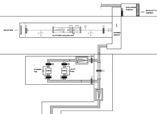
Figure 4 – Schematic of a typical platform smoke extract and ventilation system
Motor Control Centre Requirements
Selector switches will be incorporated on the fascia of the MCC. Auto/ Manual switch to disable automatic forced ventilation control. Each fan will be provided with an Off/Auto key operated switch that will spring return to auto. The key will only be removable in the Auto position. ‘Off’ will shut down the fan. On ‘Auto’ operation of the fan and associated control dampers will be at the dictates of the PLC (Programmable Logic Controller) in the MCC. When the selector switch is in the auto position the control strategy as detailed under Automatic Control will apply.
Automatic Control
In the smoke extraction mode, the fans and associated control dampers are enabled to operate automatically by the fire alarm system through activation of the smoke detectors over the platform. Upon receipt of run signal at the MCC, the appropriate smoke control and isolation dampers will be commanded open and the duty fan start, all via hardwired interlocks, and as described below. Ramp up time to full speed should take no more than 15 sec. Smoke extract mode will always take precedence over the ventilation mode. The ventilation shut down control logic will be executed once the smoke extraction run command is received.
In the forced ventilation mode, the fans and the associated control dampers are enabled to operate automatically by BMS through action of high temperature or carbon dioxide concentration sensors at the platforms. Forced ventilation modes will allow air circulation for both platforms together (whereas only the selected platform has air extracted in the smoke extract mode). In a fire condition, the forced ventilation will shut down.
In the natural ventilation mode (where provided), all dampers in the air path are opened to allow natural ventilation to both eastbound and westbound platforms. In a fire condition, the natural ventilation will shut down.
A system run signal will be received at the MCC for the standby fan by a second locally mounted fire interface unit at the same time as the duty fan. A delay-on timer will prevent the standby fan from starting immediately. A hard-wired ‘running’ interlock will be provided from the duty fan to the standby fan. The circuit will be configured as failsafe. If the duty fan has not been proved running before the standby fan delay-on timer expires, (or the running status is subsequently lost after the time delay), the standby fan will start via a hardwired latched interlock. The duty fan will be disabled and remain shut down.
The fan speed will be set on the inverter. The speed setting for the required volume will be determined at the time of commissioning. Each fan will be provided with a normally closed motorised isolation damper. Whenever a fan is required to run, its associated isolation damper will be commanded to open. The dampers will provide a hardwired interlock to the associated fan inverter (open status). The normal position of the dampers is shown in Figure 4 below. The damper open and closed status will be monitored. Once a normally closed damper is no longer closed, as detected by the end switch, the fan will be enabled to start.
Figure 5 shows the Damper Control Logic Table for the Ventilation and Smoke Extraction System for Station Platform.
Mode Normal Natural Ventilation Forced Ventilation Smoke Extraction Isolation damper- Duty Fan C O O O Isolation damper- Standby Fan C C C C Flow Control damper (Southbound) C O O O/C (as per command) Flow Control damper (Northbound) C O O O/C (as per command) Figure 5 – Damper Control Logic Table (O- Open, C- Closed)
Plant Monitoring and General Control Interlocks
Each fan will be monitored for a running status via the associated frequency inverter. Each fan will be monitored for a running status via an individual air flow proving differential pressure switch. The inverter running status and the air flow DPS (Differential Pressure Switch) will be wired in series. The running status will be indicated on the MCC fascia. The running status of the duty fan will be used as the fan failed interlock to the standby fan as earlier described. Each fan will be monitored for an inverter fault status via the associated frequency inverter. The inverter fault status will be indicated on the MCC fascia. The fan failed status will be indicated on the MCC fascia.
Volt free changeover contacts will be provided for the duty/ standby fan at the MCC to be monitored by the fire alarm system.
Firefighting Staircase Pressurisation Systems
The firefighting staircases, lobbies and lift shaft are all pressurised by duty/standby pressurisation fans. As stipulated in the design, the system may comprise of pressurisation fans, MCC, motorised control dampers and motorised intake and discharge dampers. One of the fans is always the duty fan. The fans are enabled to operate directly from the fire alarm system. There is no BMS interface.
Figure 6 shows a typical staircase pressurisation system in Crossrail.
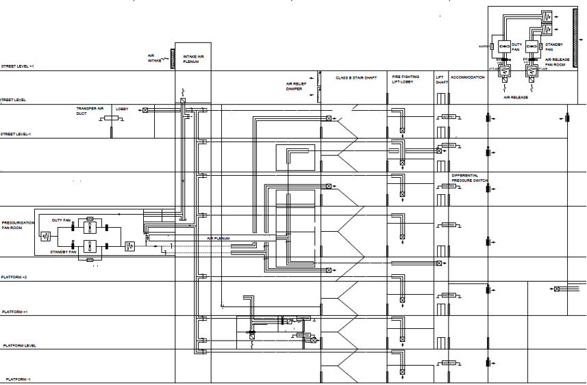
Figure 6 – A Typical Staircase Pressurisation and Air release System
Motor Control Centre Requirements
Selector switches for each fan will be incorporated on the fascia of each MCC. Each fan will be provided with an Off/Auto key operated switch that will spring return to auto. The key will only be removable in the Auto position. ‘Off’ will shut down the fan. On ‘Auto’ the fan will be stopped / started at the dictates of the fire alarm system. When the selector switch is in the auto position the control strategy as detailed under Automatic Control will apply.
In the event a fire is detected by the building’s fire alarm system, a system run signal will be received at the MCC for the duty fan by a locally mounted fire interface unit. This will start the duty fan via a hardwired interlock. The system will remain operational until the fire alarm system returns to normal. A fire man’s override will be provided to allow fire-fighters to override the fans’ automatic fire operation. For shafts and portals, provision will be made for remote on-off via SCADA.
A system run signal will be received at the MCC for the standby fan by a second locally mounted fire interface unit at the same time as the duty fan. A delay-on timer will prevent the standby fan from starting immediately. A hard-wired ‘running’ interlock will be provided from the duty fan to the standby fan. The circuit will be configured as failsafe. If the duty fan has not been proved running before the standby fan delay-on timer expires, (or the running status is subsequently lost after the time delay), the standby fan will start via a hardwired latched interlock. The duty fan will be disabled and remain shut down. The system will remain operational until the fire alarm system returns to normal.
The fan speed will be set on the inverter. The speed setting for the required volume will be determined at the time of commissioning.
Each fan will be provided with a normally closed motorised isolation damper. Whenever a fan is required to run, its associated isolation damper will be commanded to open. The dampers will provide a hardwired interlock to the associated fan inverter (open status).
Plant Monitoring and General Control Interlocks
Each fan will be monitored for a running status via the associated frequency inverter. Each fan will be monitored for a running status via an individual air flow proving differential pressure switch. The inverter running status and the air flow DPS will be wired in series. The running status will be indicated on the MCC fascia. The running status of the duty fan will be used as the fan failed interlock to the standby fan as earlier described. Each fan will be monitored for an inverter fault status via the associated frequency inverter. The inverter fault statuses will be indicated on the MCC fascia. The fan failed statuses will be indicated on the MCC fascia.
Air Release System
While the firefighting staircases, lobbies and lift shaft are pressurised by air pressurisation system, an air release system provides an air path to atmosphere for air escape from the pressurised staircase and lobby. As stipulated in the design, the system may comprise of air release fans, MCC, motorised isolation dampers, motorised control dampers, damper control panels, differential pressure sensors and air relief damper. One of the air release fans is always the duty fan. The fans are enabled to operate directly from the fire alarm system, there is no BMS interface. Figure 6 shows a typical air release system in Crossrail.
Motor Control Centre Requirements
Selector switches for each fan will be incorporated on the fascia of each MCC. Each fan will be provided with an Off/Auto key operated switch that will spring return to auto. The key will only be removable in the Auto position. ‘Off’ will shut down the fan. On ‘Auto’ the fan will be stopped / started at the dictates of the fire alarm system. When the selector switch is in the auto position the control strategy as detailed under Automatic Control will apply.
In the event a fire is detected by the building’s fire alarm system, a system run signal will be received at the MCC for the duty fan by a locally mounted fire interface unit. This will start the duty fan via a hardwired interlock. The system will remain operational until the fire alarm system returns to normal. A fire man’s override will be provided to allow fire-fighters to override the fans automatic fire operation. For shafts and portals, provision will be made for remote on-off via SCADA.
A system run signal will be received at the MCC for the standby fan by a second locally mounted fire interface unit at the same time as the duty fan. A delay-on timer will prevent the standby fan from starting immediately. A hard-wired ‘running’ interlock will be provided from the duty fan to the standby fan. The circuit will be configured as failsafe. If the duty fan has not been proved running before the standby fan delay-on timer expires, (or the running status is subsequently lost after the time delay), the standby fan will start via a hardwired latched interlock. The duty fan will be disabled and remain shut down. The system will remain operational until the fire alarm system returns to normal.
The fan speed will be set on the inverter. The speed setting for the required volume will be determined at the time of commissioning.
Air relief control will be provided to prevent over/under pressure at the accommodations. This can be achieved through the use of air relief dampers or fan speed modulation in response to door open signal (from differential pressure sensors).
Each fan will be provided with a normally closed motorised isolation damper. Whenever a fan is required to run, its associated isolation damper will be commanded to open. The dampers will provide a hardwired interlock to the associated fan inverter (open status).
Motorised control dampers in the system are used to provide an air release path from the accommodation adjacent to the firefighting stairs at the fire floor. Operation of the dampers is controlled by damper control panels via the PLC at the MCC. Address of the fire floor will be obtained from FIU at the MCC.
Plant Monitoring and General Control Interlocks
Each fan will be monitored for a running status via the associated frequency inverter. Each fan will be monitored for a running status via an individual air flow proving differential pressure switch. The inverter running status and the air flow DPS will be wired in series. The running status will be indicated on the MCC fascia. The running status of the duty fan will be used as the fan failed interlock to the standby fan as earlier described. Each fan will be monitored for an inverter fault status via the associated frequency inverter. The inverter fault status will be indicated on the MCC fascia. The fan failed status will be indicated on the MCC fascia.
Volt free changeover contacts will be provided for the duty/ standby fan at the MCC to be monitored by the fire alarm system.
Primary chilled water system
This system provides chilled water to the secondary chilled water systems. The system comprises of circulation pumps, chillers, packaged pressurisation unit, water conditioner. Each chiller will have a motorised two port isolation valve. Each chiller will have a differential pressure sensor installed across an orifice plate in order to monitor and control the flow rate through the chiller when on line. A flow measuring station is fitted in a bypass pipe between the flow and return headers. The logic is to ensure that the primary circuit supplies the secondary circuit demand, with some flow to spare, which passes through the bypass and flow meter in a positive direction (from the flow header to the return). The flow meter therefore measures the excess of supply over demand. The incremental steps of primary water are each equal to one chiller’s required flow of water. To achieve stability the system is arranged such that the flow meter enables the next chiller in the sequence on when the flow through the meter falls to around {1} l/ s and switches the pump off when the flow exceeds 120% of one chiller’s volume.
Figure 7 provides the configuration of a typical primary chilled water system in Crossrail.
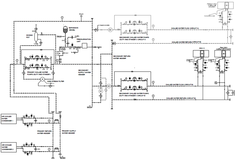
Figure 7 – Configuration of a typical primary and secondary chilled water system
Motor Control Centre Requirements
Selector switches will be incorporated on the fascia of the MCC. Each primary pump will be provided with an Off/Auto switch. ‘Off’ will shut down the device. On ‘Auto’ the device will be stopped / started at the dictates of the BMS. When the selector switch is in the auto position the control strategy as detailed under Automatic Control will apply. The switch position is monitored by the BMS. If not in auto an alarm will be raised at the BMS Operator’s Workstation. The device will be removed from the automatic control sequence.
Automatic Control
The system will be enabled via a cooling demand from any of the secondary circuit systems or a manual command by a BMS operator via the system graphic.
Following an initial cooling plant start the plant will be configured such that the lead chillers isolation valve will be commanded to open. Upon the valve being proved open by its integral end-of-travel switch, the duty primary pump will be enabled. The pump speed will be modulated as described under Primary Pump Speed Control. Upon flow being proved through the lead chiller, the chiller will be enabled to operate to the dictates of its integral controls. During this period the secondary distribution circuits will be inhibited from operating. Once the primary flow temperature has fallen to a temperature of {6} °C the secondary distribution systems will be permitted to start. Once this temperature has been achieved, this interlock will be latched for the remainder of the operating period. Subsequent chillers will be enabled / disabled as described under Chiller Sequence Control.
When the primary pumps are enabled, the speed of the pump will be modulated via proportional plus integral control loops in order to maintain the required flow rate through the chillers. An orifice plate will be located within the flow pipework of each chiller. Connected to each of the orifice plates will be a differential pressure transmitter that will measure the flow rate through chiller. The flow signal will be calibrated in l/s and will be displayed on the BMS Operator’s Workstation system graphic. As each chillers isolation valve reaches the open position, a control loop for that chiller will be enabled. The primary pumps speed will be modulated to the dictates of the control loop with the maximum demand. When a valve is commanded to close, its associated control loop will be disabled when the valve open switch breaks.
The lead chiller will be enabled permanently whilst the system is required providing all safety interlocks are healthy. The lag chillers will be enabled and disabled under the dictates of the measured flow rate through the flow measuring station located across the primary flow and return headers as follows:
On increasing demand, the lag chiller will be enabled when the primary flow, as sensed by the flow measuring station, falls to a set point of {1} l/s and is sustained at or below this level for a period of {1} minute. The increasing demand control logic will be frozen at this point. Once the lag chiller has been enabled for greater than {10} minutes, the demand based control logic will be re-enabled. On decreasing demand, the lag chiller will be disabled when the primary flow, as detected by the flow measuring station, rises to a set point of {120} % of one chillers required flow rate duty and is sustained at or above this level for a period of {1} minute. Once the lag chiller enabled has been disabled for greater than {10} minutes, the demand based control logic will be re-enabled. The lead chiller will always remain enabled whilst the system is required. When a chiller is no longer required, the chiller will first be disabled. After a suitable run-on time the associated isolation valve will be commanded to close.
When the system is required to shut down, the secondary distribution systems will be commanded to stop if not already stopped. All enabled chillers will be disabled. After a suitable run time, the lag chiller isolation valve will be commanded to close if open. Once the lag valve is closed, the primary pumps will be shut down. Once the primary pumps are shut down, the lead chiller valve will be commanded to close.
The lead/ lag selection will be rotated on an hours run or failure basis. The sequence selection will rotate on an hours run basis set at [200] hrs. The current sequence will be indicated on the BMS Operator’s Workstation system graphic. The BMS operator will be able to change the sequence via a command at the BMS Operator’s Workstation system graphic. The BMS operator will be able to inhibit the automatic hours run sequence changeover function via a command at the BMS Operator’s Workstation system graphic. The sequence changeover function will be inhibited if any chiller is not available or in a failed condition.
Plant Monitoring and General Control Interlocks
The hours run for each pump and chiller will be derived from the individual device running status and indicated on the BMS Operator’s Workstation system graphic. An operator should be able to configure a limit alarm for the hours run for each device. The BMS will monitor each chiller for a running status. Indication will be provided on the BMS Operator’s Workstation system graphic and the MCC fascia.
The BMS will monitor each chiller for a common fault. Should the common fault operate, a ‘fault’ lamp will illuminate on the MCC fascia and an alarm will be raised on the BMS Operator’s Workstation. The BMS will disable the chiller enable command. The chillers lead sequencing will be set so that the failed chiller is last in the sequence, i.e. the lag chiller. Subsequent changes of the lead changeover function will be inhibited. After a suitable run-on period, the failed chiller’s isolation valve will be commanded to close.
When any chiller is required to operate, a chiller will only be permitted to run when all of the required interlocks are satisfied. These interlocks will be monitored on the BMS and will be duplicated by the BMS software to prevent unnecessary alarms.
Each of the primary pumps will be monitored for a running status via the associated frequency inverter’s running status and a common differential pressure switch piped across the pump set wired in series. In the event of a pump failure, as detected by a mismatch between the BMS command to the pump and the pump status, an alarm will be raised on the BMS Operator’s Workstation and the pump will be commanded off. A fault flag for the pump will be set in software. The pump will remain shut down until the pump failure flag has been reset. The standby pump will be started. The pump failure alarm will be inhibited for a grace time after the enable command is given to allow time for the pump to start and run up to speed. The failed pump will remain out of automatic control until the fault flag is reset by an operator at the BMS Operator’s Workstation. In the event of an inverter fault being reported, an alarm will be raised on the BMS Operator’s Workstation but the pump will continue to run, unless the fault is of a nature to fail the pump, in which case the normal pump failure shut down applies. Pump ‘running’ and ‘fault’ indication will be provided on the MCC fascia derived from the run and fault contacts respectively in the applicable inverter.
An independent low pressure switch will be located in the primary CHW (Chilled Water) circuit common return pipework for low water interlocking purposes. The chillers and all primary and secondary CHW pumps will be shut down by the BMS in a controlled manner. Indication will be provided on the MCC fascia of ‘low pressure’. A general alarm will be raised at the BMS Operator’s Workstation. The BMS will restart the plant automatically once the low pressure condition returns to normal. If the low pressure condition is still present after 15 minutes, as determined by a hard-wired timer, a hard-wired interlock will isolate all pumps and chillers immediately. This will be a latching circuit which will be reset by a fascia mounted pushbutton once the low pressure condition has returned to normal. The circuit will be arranged so as not to latch following a power failure.
An independent high pressure switch, located in the primary CHW circuit common return pipework, will be provided for high pressure interlocking purposes. In a high pressure condition, the chillers and all primary and secondary CHW pumps will be shut down by the BMS in a controlled manner. Indication will be provided on the MCC fascia of ‘high pressure’. An alarm will be raised at the BMS Operator’s Workstation. The BMS will restart the chillers automatically once the high pressure condition returns to normal.
The BMS will monitor the individual chiller flow temperatures, the common flow temperature and the common return temperature. The temperature sensor located in the primary chilled water circuit flow pipework will provide ‘High Temperature’ alarms when the measured temperature exceeds [8] °C. These alarms will be inhibited for {15} minutes on a normal initial start-up.
Secondary Chilled Water Systems
This system provides chilled water to AHUs, Fan Coils and CCUs as applicable in the design. As stipulated in the design, the system may comprise of duty/ standby variable volume pumps, remote differential pressure sensor, flow and return water temperature sensors. Figure 7 provides the configuration of a typical secondary chilled water system in Crossrail.
Motor Control Centre Requirements
Selector switches will be incorporated on the fascia of the MCC. Each pump will be provided with an Off/Auto switch. ‘Off’ will shut down the device. On ‘Auto’ the device will be stopped / started at the dictates of the BMS. When the selector switch is in the auto position the control strategy as detailed under Automatic Control will apply. The switch position is monitored by the BMS. If not in auto an alarm will be raised at the BMS Operator’s Workstation. The device will be removed from the automatic control sequence.
Automatic Control
The system will be enabled via a cooling demand from AHU, fan coil or CCU (Close Control Unit) or a manual command by a BMS operator via the system graphic. The system will be disabled when no cooling demand exists or via a manual ‘Off’ command from the BMS Operator’s Workstation or any safety interlocks operating.
Upon a demand to start, a cooling demand signal will be sent to the CHW primary system to start. The secondary pump system will remain disabled. Once the CHW primary system has started and proved running, and the CHW flow temperature has reached set point, the duty secondary pump will be enabled, and the speed modulated as described under System Differential Pressure Control.
When the system is required to shut down, the cooling demand signal will be removed from the primary system. Then the secondary pump system will be shut down.
Differential pressure sensors will be installed across the flow and return pipework at AHU and used to modulate the speed of the pumps. The BMS will modulate the speed of the running pump to maintain the differential pressure at a set point of {***} kPa via a proportional plus integral action control loop. Where more than one differential pressure sensor is installed, the pump speed will be modulated to satisfy the sensor most in demand, either too high a pressure to decrease speed or too low a pressure to increase speed. In the event of a differential pressure sensor failure or field wiring open or short circuit, the sensors control loop will be removed from the automatic control regime and not used in the speed control function. An alarm will be raised at the BMS operator’s station indicating the sensor fault. The pumps speed will be set at a default value of {25} Hz.
Plant Monitoring and General Control Interlocks
The hours run for the each pump will be derived from the individual pump running status and indicated on the BMS Operator’s Workstation system graphic. An operator should be able to configure a limit alarm for the hours run for each pump.
The pump set will be interlocked with the systems high and low pressure switches. During cooling plant shut down periods and where any part of the system is exposed to outside air conditions, should the outside air temperature fall to {1} °C, the secondary chilled water system will be enabled to circulate water around the system. A cooling demand will not be generated to the primary systems. The secondary system will continue to operate until either the outside air temperature rises to above {3} °C or a cooling demand is received from the associated AHUs, FCUs or CCUs, where the system will revert to normal control. The frost protection status will be indicated on the system graphic. The BMS, via the communication network, will command an appropriate number of AHUs’, FCUs’ or CCUs’ valves to the fully open position.
The duty selection will be carried out on hours run basis. The duty/ standby selection will rotate on an hours run basis set at [200] hrs. The current duty will be indicated on the BMS Operator’s Workstation system graphic. The BMS operator will be able to change the duty via a command at the BMS Operator’s Workstation system graphic. The BMS operator will be able to inhibit the automatic hours run duty changeover function via a command at the BMS Operator’s Workstation system graphic. The duty changeover function will be inhibited if either pump if is not available or in a failed condition.
Each of the secondary pumps will be monitored for a running status via the associated frequency inverter’s running status and a common differential pressure switch piped across the pump set wired in series. In the event of a pump failure, as detected by a mismatch between the BMS command to the pump and the pump status, an alarm will be raised on the BMS Operator’s Workstation and the pump will be commanded off. A fault flag for the pump will be set in software. The pump will remain shut down until the fan failure flag has been reset. The standby pump will be started. The pump failure alarm will be inhibited for a grace time after the enable command is given to allow time for the pump to start and run up to speed. The failed pump will remain out of automatic control until the fault flag is reset by an operator at the BMS Operator’s Workstation. In the event of an inverter fault being reported, an alarm will be raised on the BMS Operator’s Workstation but the pump will continue to run, unless the fault is of a nature to fail the pump, in which case the normal pump failure shut down applies. Pump ‘running’ and ‘fault’ indication will be provided on the MCC fascia derived from the run and fault contacts respectively in the applicable inverter.
The BMS will monitor the common flow temperature and the common return temperature. The temperature sensor located in the secondary chilled water circuit flow pipework will provide ‘High Temperature’ alarms when the measured temperature exceeds [8] °C. These alarms will be inhibited for {15} minutes on a normal initial start-up.
-
Authors

Wing Fung PhD MSc BSc(Eng) CEng MCIBSE - Arcadis
Technical Director (MEP), Arcadis
Wing is is a Chartered Engineer with over 30 years’ experience as a technical specialist engaged in mass transit system planning, design, project management, technical assurance, commissioning, energy management, operation and maintenance, and asset renewal. Wing has been with the Crossrail project in the CRL Chief Engineer Group since 2013, overseeing mechanical design, systems integration and T&C.
Specialties: Building Services, Mechanical Engineering, Computational Fluid Dynamics, RAM studies, Systems Integration, Requirement Management, Testing and Commissioning.
