Corrosion Control in a Tunnel Environment
Document
type: Technical Paper
Author:
Tom Grady, ICE Publishing
Publication
Date: 30/09/2017
-
Read the full document
Introduction
This paper builds upon the work previously undertaken to determine the corrosion classification of MEP equipment at various Stations, Shafts and Portals [1] by extending this study into a tunnel environment. Using processes and definitions set by British and International Standards in conjunction with geological data, ground water chemical analysis and tunnel environmental operating conditions, the corrosive classification of a tunnel environment can be determined.
In addition to the general tunnel environment conclusions drawn and outlined later in this paper, specific locations have been addressed that may require special consideration due to particularly corrosive processes. Analysis of a number of factors contributing to corrosive processes have been addressed, most notably the geological implications of the ground surrounding a tunnel drives and the material selection within the tunnels, possibly leading to galvanic corrosion. Any specific areas throughout a tunnel environment that may require an increased level of corrosion protection have been addressed, detailing both the conditions of the localised areas and requirements necessary to achieve the desired operating life.
Purpose
- To determine how corrosive the general tunnel environment is, considering all contributory factors including humidity, particulate pollution, chemical pollution and tunnel water seepage.
- To review relevant geological surveys and chemical analysis of ground water to determine key areas of a tunnel that may have an increased risk of water seepage and a more corrosive atmosphere.
- To present information regarding the use of metallic materials and the potential for aggressive galvanic corrosion in certain circumstances, and to present mitigating actions to limit the effect of this. Any known cases where galvanic corrosion is likely to occur will also be described.
- To outline key areas that are at particular risk of corrosion due to any of the factors described in the paper.
- To present clear recommendations as to how metallic materials should be protected from corrosion using corrosion ratings set out in British and International Standards, and to describe what further measures may be required in sections of a tunnel that are deemed to be highly corrosive.
Scope
This paper provides a more justified approach to corrosion classification of MEP equipment in differing tunnel environments. The method through which classifications are made will be backed up by relevant standards and industrial information.
Definitions
BS British Standard
CEG Chief Engineer’s Group
CRL Crossrail
E/B Eastbound
MCR Material Compliance Report
MEP Mechanical, Electrical & Public Health
OHLE Over Head Line Equipment
PML Pudding Mill Lane
RH Relative Humidity
ROP Royal Oak Portal
SCL Sprayed Concrete Lining
SGS Stepney Green Shaft
SS&P Stations, Shafts & Portals
W/B Westbound
Procedure
Fundamentals & Background Information behind Corrosion
Equipment Life Requirements
Crossrail assets are designed for a life of 120 years, with appropriate maintenance/replacement strategies in place. Within reason, the life of equipment within a tunnel environment must be maximised; i.e. expensive methods of applying corrosion protection should not be applied to relatively cheap components for small gains in fixture life expectancy. The minimum life to fixture replacement is deemed to be 30 years [1].
Corrosion Categories
Table 1 outlines the corrosion categories C1 to C5 in accordance with BS EN ISO 12944-2:2009 [2]. , and the typical environmental conditions these categories refer to.
Table 1: Description of typical atmospheric environments related to the estimation of corrosivity categories

Table 2 outlines typical corrosive values, from BS EN ISO 9223:2012 [3], for carbon steel, zinc, copper and aluminium at each of these conditions, displaying values in both loss of mass (g/m2/year) and loss of thickness (μm/year). The values displayed in Table 2 are of particular importance, given that after determining the corrosivity of the atmosphere and applying a C-rating, the final component is likely to be coated in one of the anodic metals displayed in this table (zinc, copper and aluminium), meaning the determination of the thickness of this coating is crucial to ensuring components achieve their design life.
Table 2: Corrosion rates, rcorr, for the first year of exposure for the corrosivity categories outlined in Table 1
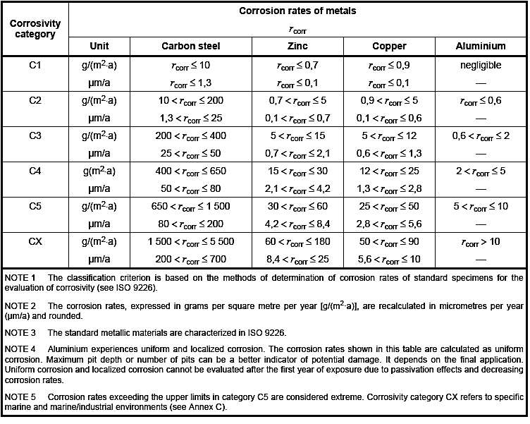
In Table 2, CX can be taken to represent C5 (M), and C5 to represent C5 (I), which indicate marine and industrial environments respectively.
Contributory Factors to a Corrosive Atmosphere
The corrosivity of the atmosphere within a tunnel environment is dependent on a number of key factors; the relative humidity (RH), the deposition of sulphur dioxide (SO2), the deposition of Chlorine anions (Cl–), and the presence of particulate contaminants that can act as a catalyst and accelerate corrosion on a surface. SO2 and Cl– deposition is dependent upon the atmospheric condition and how much of these chemical substances it carries from sources like evaporated ground water. In a tunnel environment, particulate contaminants can arise from a number of sources including but not limited to metallic dust from the railway OHLE equipment (aluminium, copper and brass) and carbon steel dust from friction between the train wheel and track as well as the brake pads utilised on the rolling stock.
BS EN ISO 9223:2012 [3] sets out a method of estimating how corrosive an atmosphere is, taking the factors outlined above into account. Section 8.2 outlines an equation to determine the corrosive rate of a number of different metals. Equation 1 outlines this relationship for carbon steel.
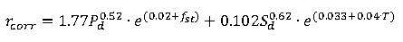 Where:
rcorr =
First year corrosion rate of metal, in micrometres per year (μm/a) Pd = Annual average SO2 deposition, in milligrams per metre square per day (mg/m2d) fst = Steel specific factor (equation found in BS EN ISO 9223:2012) Sd = Annual average Cl– deposition, in milligrams per metre square per day (mg/m2d) RH = Relative humidity (%) T = Annual average temperature (°C) Similar equations are published to determine first year corrosion losses for zinc, copper and aluminium. These losses can be used in conjunction with the mathematical analysis outlined in BS EN ISO 9224:2012 [4] to determine the total loss of material experienced over a given number of years; due to the changing rate of corrosion. Experimental methods for determining the SO2 and Cl– deposition rates are outlined in BS EN ISO 9225:2012 [5].
While the rate of corrosion within a tunnel environment has not been determined to the level of accuracy outlined, this information is provided in order to carry out a more detailed analysis of the corrosivity of a tunnel atmosphere in the future should resources allow. Some empirically based assumptions can be made. A system specification for tunnel ventilation states the following assumptions for the temperature and relative humidity of different generic tunnel environments.
Table 3: Temperature & humidity estimates for areas within a tunnel environment
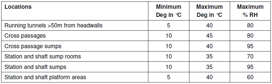
The maximum relative humidity is estimated to be relatively high throughout the tunnels and cross passages at 80%. Whilst this estimation is not backed up in terms of potential sources of moisture that may increase the relative humidity at higher temperatures, e.g. evaporating rainwater as a train enters a tunnel environment or expelled condensate from rolling stock’s on board air conditioning system, it is taken from the report’s context that this estimation is conservative; i.e. it estimates the relative humidity of a tunnel environment to be higher than in practice.
Ground water Seepage
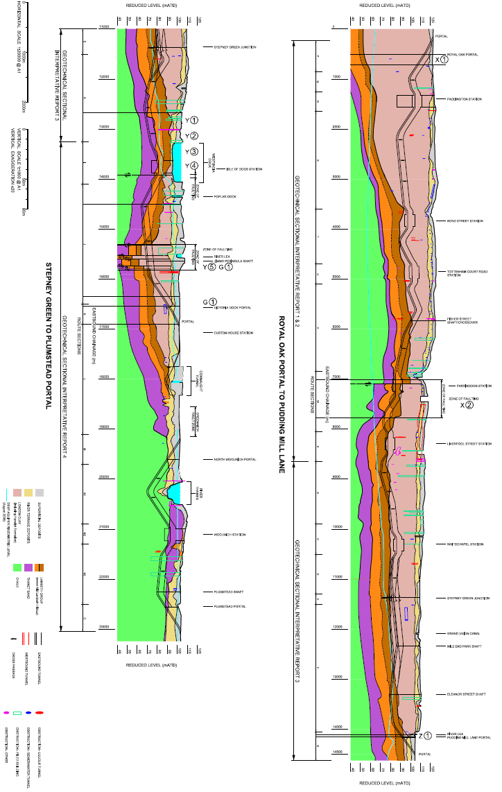
The severity of corrosion within a tunnel environment is enhanced significantly where tunnel seepage of ground water occurs. The risk of this taking place depends on a number of factors; the type of ground the tunnels are constructed within, the depth of the tunnels, the condition of the tunnels and the location within a tunnel. The last of these factors refers to places like shafts, cross passages and stations where the concrete tunnel segments interface with SCL or other materials which increase the risk of seepage. A geological survey of the ground through which the tunnels are constructed was undertaken by the Crossrail geotechnical department, and is shown in Figure 1.

Figure 1: Geotechnical survey of stratigraphic units Crossrail tunnels run through
Figure 1 shows the various stratigraphic units of the London landscape the Crossrail tunnels encounter, and this can aid in determining the areas where tunnel seepage is likely to occur. Table 4 shows the superficial fluid flow velocity for each of the stratigraphic units shown in Figure 1, which gives an indication as to how much resistance the earth provides to moving water.
Table 4: Superficial Fluid Flow Velocities for different stratigraphic units of London terrain.
Type of Ground Superficial Fluid Flow Velocity, us (m/s) London Clay 10-10 Lambeth Group (Clay) 10-10 Lambeth Group (Sand) 10-6 Thanet Sand 10-6 Chalk (Intact) 10-7 Chalk (Fissured) 10-4 Given the information outlined in Table 4 and the known properties of each type of terrain as described in Section 4 of the Environment Agency’s report ‘Ground water Quality Review: London Basin’ [6], it can be established that tunnels constructed through clay terrain are unlikely to experience seepage problems, whilst all other types of geology pose a risk of tunnel seepage. The areas where a tunnel is surrounded by chalk are of particular concern.
It should also be noted that the deeper a tunnel is beneath the water table, labelled as the ‘deep aquifer piezometric level’ in Figure 1, the higher the water pressure upon a tunnel, increasing the risk of tunnel seepage.
Galvanic (Bimetallic) Corrosion
An important factor to take into consideration in material selection for metallic fixings within a tunnel environment is the occurrence of galvanic corrosion. Galvanic or bimetallic corrosion is an electrochemical process that causes one metal to corrode preferentially when in contact with a different metal, in the presence of an electrolyte. The severity of this effect is governed by two important factors; the electro-potential difference between the two metals, a direct result of different metals possessing different electrode potentials, as well as the conductivity of the electrolyte. The nobler of the metals will act as a cathode, whilst the other acts as an anode and will corrode preferentially. In a conductive electrolyte, such as salty water, this reaction is accelerated.
An example of how this process operates is the galvanisation of steel components using an anodic zinc layer. This not only increases corrosion resistance, as the corrosion rate of zinc is significantly lower than steel, as shown in Table 2, but it means that if the zinc layer were to be damaged and expose the steel, the steel would not be targeted by corrosive attack until the zinc layer had disintegrated, as both metals are in contact with an electrolyte.
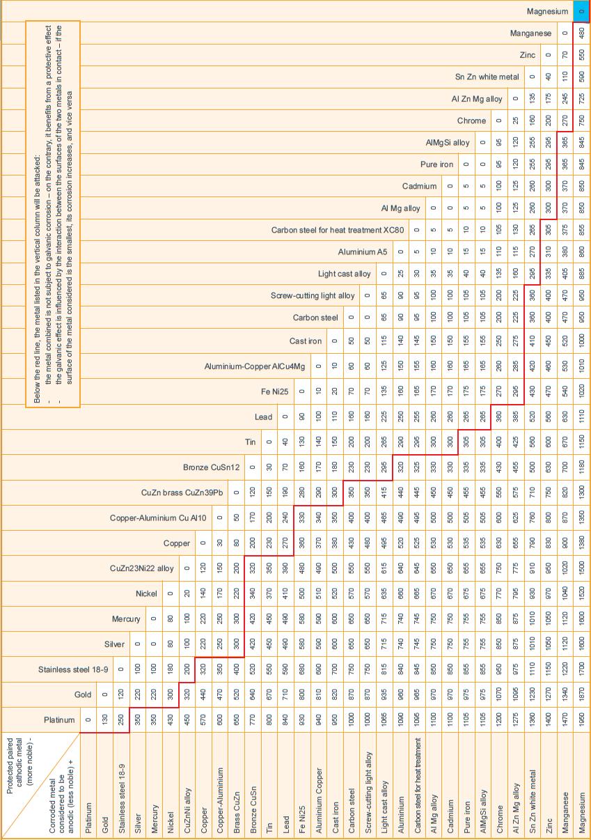
Figure 2 presents a chart extracted from industry guidelines to aid in determining the effect galvanic corrosion may have upon certain metals. The anodic metals displayed in the left hand column will (noticeably) corrode preferentially if they are placed into contact with a dissimilar metal and the corresponding number appears below the red line. The magnitude of this number is the electrochemical potential between the metals (in mV), and therefore proportionate to the severity of the corrosive attack upon the anode. It should be noted that this electrochemical potential is dependent upon a number of factors including temperature, and may vary in different circumstances.
To give an example, if Magnesium and Platinum are placed in contact with each other in the presence of an electrolyte, Magnesium will corrode preferentially at a very high rate; whereas it will corrode at a much lower rate if it is placed into contact with Silver.
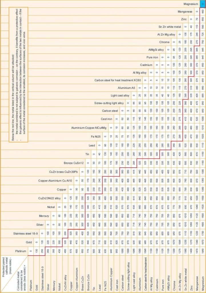
Figure 2: Table to show electro-potential between different metals, leading to galvanic corrosion
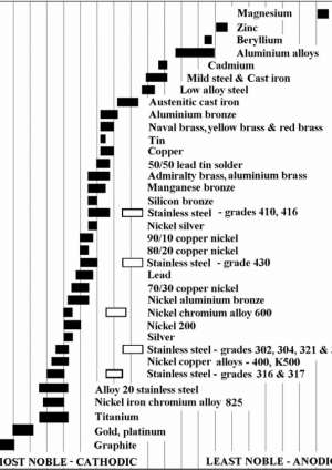
Figure 3 presents a chart designed to aid in determining the anodic metal in a given bimetallic couple. Whilst this can also be done using Figure 2, Figure 3 can be utilised as a quick and easy to use guide on the nobility of metallic materials. It should be noted that chromium based alloys, specifically stainless steels, have two different states; the black box representing an active state, and white box passive. This is owed to a passive alloy exhibiting a chromium rich oxide layer on the surface offering much improved corrosion resistance. For these purposes, stainless steels should always be assumed to be passive.

Figure 3: Guide to nobility of metallic materials used in construction
Ratio of Areas
To describe the importance of the ratio of areas of the anode to the cathode, the process by which galvanic corrosion occurs must first be understood. The process occurs as the electrochemical potential between the two metals causes a current to flow between them; this current flows through an electrolyte. The higher the potential and the more conductive the electrolyte, the larger the driving force behind the current and the less resistance there is to current flow. It should be noted that in the absence of an electrolyte, this current cannot flow so galvanic corrosion would not occur. Owing to this current travelling between the metals, 2 reactions occur, anodic and cathodic. The anodic reaction is the dissolution of the metal, i.e. the corrosion, while the cathodic, or reduction, reaction usually takes the form of reducing either dissolved oxygen or hydrogen ions within the electrolyte solution upon the cathode’s surface.
For every anodic reaction that takes place, a cathodic reaction must also occur. In a static situation, the rate of anodic reaction, and therefore corrosion rate, is proportional to the cathode surface area exposed to the electrolyte; the larger the cathodic area in contact with the electrolyte, the larger the available area for cathodic reactions to take place. Figure 4 illustrates this principle in a practical situation.
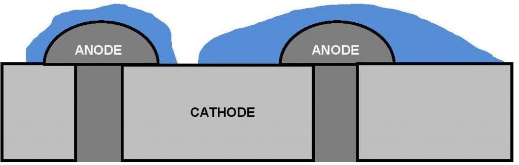
Figure 4: Pictorial representation of different corrosion rates
Figure 4 shows 2 galvanised anodic bolts, zinc, secured into a cathodic metallic body, e.g. stainless steel. The anodic area in contact with the electrolyte is the same in both situations, but the electrolyte in the situation on the right hand side is in contact with a much larger cathodic surface area than that on the left. The rate of corrosion upon the anode will be much higher on the head of the right hand bolt than the left, as there are a higher number cathodic reactions, which in turn produces more anodic reactions which are concentrated upon the same anodic surface area. Figure 5 illustrates a more useful example, given this particular use of materials is proposed for potential use in the Crossrail project.

Figure 5: Example of material selection proposed for lighting fixtures within a tunnel environment
In this example, stainless steel bolts are placed into contact with an aluminium retaining structure. Given the situation where water leaks into the structure, a scenario similar to that shown in Figure 5 may occur. In this particular example, it is clear to see that the anodic area in contact with the electrolyte is relatively small in comparison with the cathodic area; this gives rise to an accelerated attack upon the aluminium retaining structure which could potentially fail as the corrosion would be concentrated in the areas where the electrolyte is in contact.
The scenarios outlined in Figures 4 and 5 serve as an example of how the ratio of anodic to cathodic materials can intentsify the problem of galvanic corrosion; they are in no way accurate to real life situations. When selecting materials for use in a tunnel environment, the anodic/cathodic area ratio should be maximised (especially in areas where tunnel seepage is deemed to be high risk), and structures should be designed to minimise the collection of water so there is no build up of potential electrolyte. Further details about galvanic corrosion, and the chemsitry behind it, can be found in BS PD 6484:1979 [7].
Corrosion Classification
General Corrosion Classification
Taking the information outlined previously, a corrosion category for the general tunnel environment can be determined. In the absence of a detailed study to determine location specific values for relative humidity, SO2 pollution and Cl– pollution, some assumptions are made to determine how the environment should be classified. In the absence of tunnel seepage, the sources of SO2 and Cl– pollution within a tunnel are limited. With this in mind and momentarily neglecting areas where the tunnel seepage is likely to occur and taking the assumption that the maximum relative humidity within a tunnel environment is 80%, the general tunnel environment should be rated at C3; i.e. ‘[areas] with high humidity and some air pollution’ in reference to Table 1.
BS EN ISO 14713-1:2009 [8] provides details for different methods of zinc coating components and the life to first maintenance for varying thicknesses.
Table 5: Life to first maintenance for a selection of zinc coating systems in a range of corrosivity categories [8]
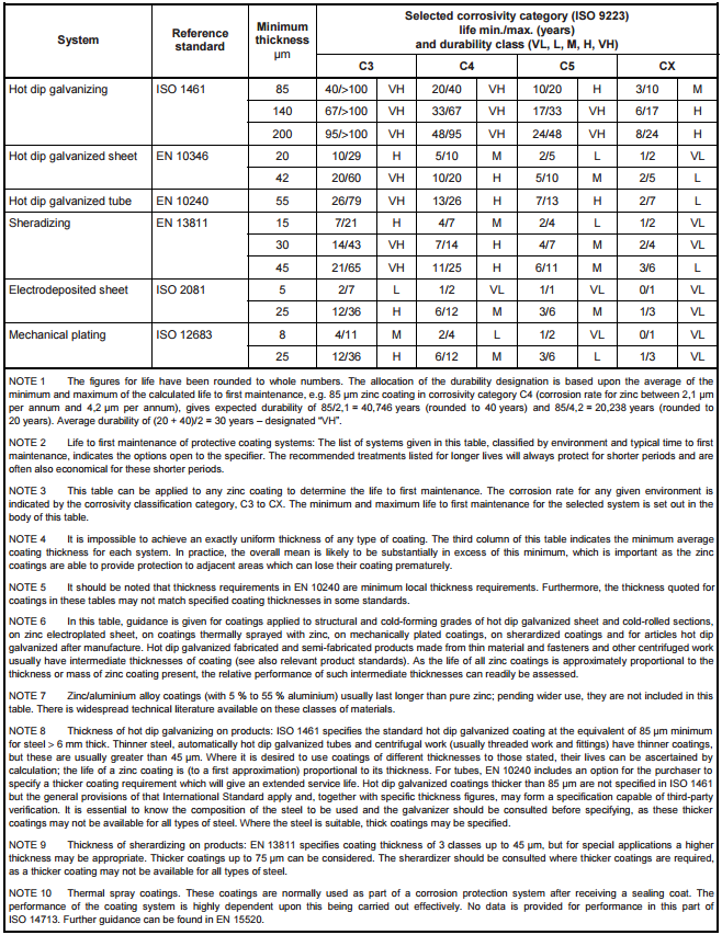
Table 5 presents useful information regarding the requirements of metallic coating thicknesses required for different corrosive conditions; however, there are some issues with the practicality of applying these coatings. In practice, it is difficult to achieve a zinc coating of much thicker than 140μm through hot dip galvanizing. This paper outlines only the corrosion ratings of a tunnel environment.
Corrosion Classification with Tunnel Seepage
Where there is a risk of ground water seeping into a tunnel bore, the corrosivity of the environment increases. Areas deemed to have a higher risk of tunnel seepage will be rated at C4, while certain areas deemed to be high risk will have corrosion ratings of C5. A schedule of specific tunnel drives and associated corrosion classifications is provided in the corrosion protection schedule, but as a general rule:
- Tunnel drives through London Clay are deemed to be at low risk of tunnel seepage and will be designated a corrosion rating of C3.
- Tunnel drives through Lambeth group, Thanet sand and Chalk are at a higher risk of tunnel seepage, and will be designated a corrosion rating of C4.
- Areas where leakage has occurred previously, where a tunnel has been damaged during construction or have been designated at high risk of tunnel seepage, such as tunnel interfaces at SS&P, will be designated a corrosion rating of C5.
Table 1 outlines the general environmental conditions for a C5 classification as ‘areas with almost permanent condensation and high pollution’. It also compares it to ‘coastal areas with high salinity’. C5 is a relatively extreme corrosive category that technically should not apply to many areas which have been designated as such in this report. These measures have been taken as a precaution where tunnel seepage is more unpredictable.
It should be noted that at the time of publishing, tunnel seepage recorded is well below the limit of 0.12 litres/day/m2, as indicated in KT10.1301 – Performance Requirements (Water tightness of Non-SCL Tunnels and Shafts) [9]. Even if seepage levels were higher, the salinity of this ingress is estimated to be around 0.4%. This is around 1/10th the salinity of seawater; further evidence that a C5 corrosion rating may be excessive in a majority of tunnel sections.
Corrosion Protection Schedule
Taking into account the information outlined previously, and the geological survey presented on ground water seepage; a schedule of corrosion protection recommendations is presented below in Table 6. In order to produce this schedule, a number of key locations at high risk of tunnel seepage, and therefore C5 corrosion category, have been identified:
- Areas where a tunnel has been damaged and seepage is deemed likely to occur, or areas where noticeable leaks have occurred already. These can be obtained from tunnel repair records.
- Interfaces between the concrete tunnel segments and the SCL in SS&P and cross-passages extending 10m down a tunnelled section from the demarcation line. It should be noted here that all cut and cover sections of portals leading up to a tunnel eye should also be rated C5.
- Cross-passages CP13 to CP15, where a zone of faulting may cause earth and therefore tunnel segments to shift, increasing risk of damage and seepage.
- Connaught tunnel (portal to portal).
- Thames tunnel (North Woolwich Portal to Woolwich station).
Whilst this report provides a researched guide to corrosion protection throughout the Crossrail tunnels, a risk based approach must always be used when assessing protection on site. If site engineers deem a stretch of tunnel to be particularly risky, or a certain section of tunnel is found to exhibit leaks, which is not outlined in this report, C5 protection should be applied accordingly.
Table 6: Schedule of corrosion ratings for different sections of tunnel
C3
C4
C5
Central Section
(ROP – SGS)
Royal Oak Portal – Fisher Street Shaft
(E/B & W/B)
Fisher Street Shaft – CP8
(E/B & W/B)
CP8 – Whitechapel Station
(E/B & W/B)
Whitechapel Station – Stepney Green Shaft
(W/B ONLY)
Whitechapel Station – Stepney Green Shaft
(E/B ONLY)
Eastern Section
(SGS – PML)
Stepney Green Shaft – Mile End Park Shaft
(E/B ONLY)
Stepney Green Shaft – Mile End Park Shaft
(W/B ONLY)
Mile End Park Shaft – Pudding Mill Lane Portal
(E/B & W/B)
Eastern Section
(SGS – PLUMSTEAD)
Stepney Green Shaft – CP13
(E/B & W/B)
CP13 – CP15
(E/B & W/B)
CP15 – Victoria Dock Portal
(E/B & W/B)
Connaught Tunnel
(E/B & W/B)
North Woolwich Portal – Woolwich Station
(E/B & W/B)
Woolwich Station – Plumstead Portal
(E/B & W/B)
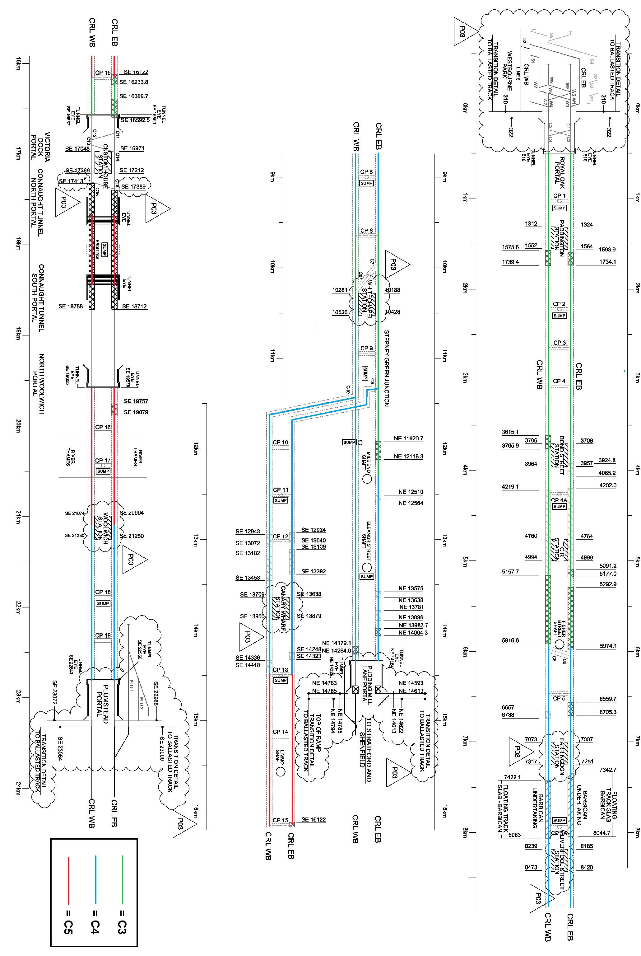
Figure 6 shows tunnel drives and their associated corrosive environments on a schematic, as an aid to understand the designations. This schematic was created using an altered version of the trackform extents map C610-ATC-R4-DDE-CR001-Z-76001 [10]. Tunnel sections highlighted green are to be rated C3, blue to be C4 and red to be C5. This schematic must be viewed in colour to be understood.
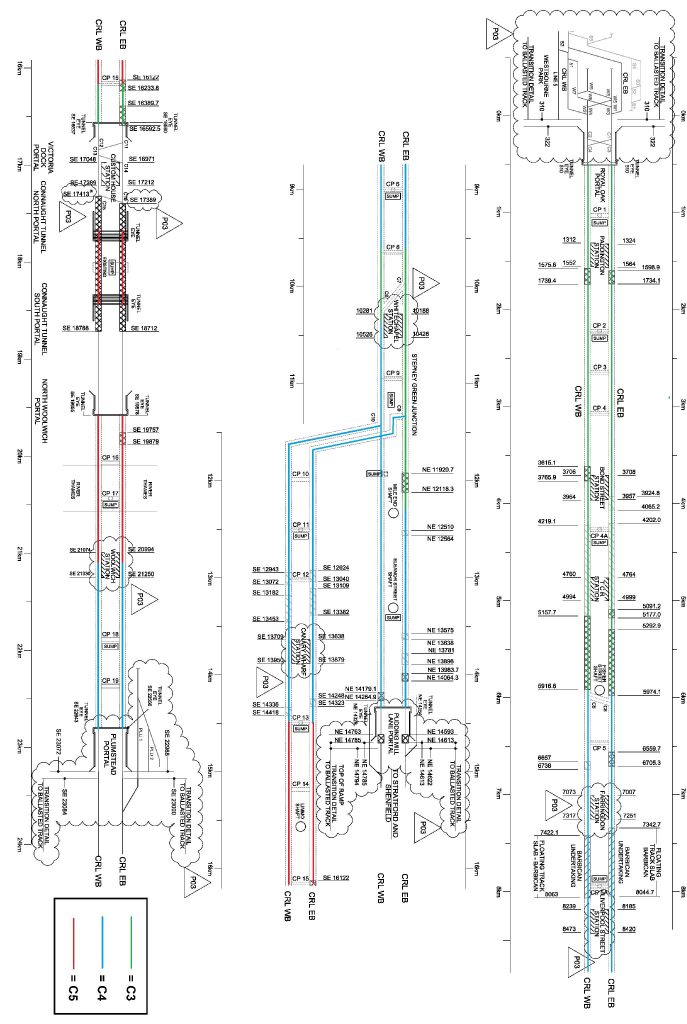
Figure 6: Schematic to show corrosion ratings for different tunnel sections
In addition to the corrosion specifications for the different tunnel sections outlined in Table 6, the specifications for areas where tunnel damage, pre-existing leaks and interfaces must also be taken into account.
Galvanic Corrosion Classification & Mitigation
The possible occurrence of galvanic corrosion must be considered when selecting materials for use within a tunnel environment. This is especially true where seepage is deemed likely to occur, i.e. tunnel sections designated C5 in Table 6. Connaught tunnel is perhaps the most important of these areas, given the high degree of the water ingress into this tunnel.
If dissimilar metallic components are going to be in contact the electrochemical potential between the metals must be determined using Figure 2. It should be noted that carbon steel components will almost always be protected in some form using a zinc coating.
If the contact between dissimilar metals is deemed to be a problem in its given environment, there are two different actions that can be taken. The first is to simply change one of the materials to reduce the galvanic potential that may exist; the other is to make use of an electrical insulator between the metals (such as a neoprene washer or barrier), which would guarantee that no galvanic corrosion would occur in the presence of an electrolyte.
It should be noted that while the table presented in Figure 2 provides a basic standard to understand the galvanic potential between different metals, it should be used with care. To illustrate this, the example of a tunnel’s walkway, constructed from aluminium and galvanised steel, and which is perhaps the most prominent example of dissimilar metals being used. Using Figure two and matching zinc and aluminium, the conclusion is drawn that the number lies below the red line and the zinc will therefore be attacked. This may not necessarily be true; the potential is actually relatively small (only 10 mV above the threshold for this critical line), and there are given industrial examples where zinc and aluminium have been in contact in a damp/wet environment and no galvanic corrosion has occurred. Nevertheless, the potential does still exist, and if there is any risk of tunnel seepage that could lead to a situation in which the electrolyte covers a larger area of cathodic aluminium to anodic zinc, which is likely given the size of bolt heads, mitigation may be needed.
The key to avoiding corrosion is to understand what materials are in contact, and with this knowledge to determine whether further protection is required; a risk based approach. Many components are galvanised with zinc and some have further protection in chemically inert coatings which would eliminate the risk of galvanic corrosion.
Whilst the circumstances of each individual situation must be taken into account, the following list outlines pairs of metals that may appear in a tunnel environment that are not advised, with those in bold italic as particularly high risk. The figure in brackets preceding the bimetallic pairs is the estimated galvanic potential.
- Copper & Stainless Steel (320 mV)
- Copper & Carbon Steel (430 mV)
- Copper & Aluminium (520 mV)
- Brass & Carbon Steel (350 mV)
- Brass & Aluminium (440 mV)
- Aluminium & Stainless Steel (840 mV)
- Zinc & Stainless Steel (1150 mV)
- Zinc & Copper (830 mV)
- Zinc & Brass (750 mV)
- Zinc & Carbon Steel (400 mV)
- Zinc & Aluminium (310 mV)
- Carbon Steel & Stainless Steel (750 mV)
Considering the relatively common use of stainless steel in bolts and other components in construction, and the clearly high risk it poses, using both the example outlined in the section on Galvanic Corrosion and the high risk combinations outlined in this section, the use of stainless steel in a tunnel environment is not advised where other common structural metallic materials are being used. This is not true in all circumstances, but should be applied as a general rule.
Conclusion
Using definitions and guidance taken from a number of British and International standards, the general tunnel environment is deemed to be C3. This definition applies where tunnels are deemed to be relatively safe from ground water seepage, which, from geotechnical research, is the case when tunnels are bored through London Clay. Where the risk of tunnel seepage increases as a tunnel is bored through Lambeth group and Thanet sand geology, the corrosive category rises to C4. In areas where tunnel seepage is deemed likely to occur, such as where a tunnel is damaged, interfaces with cross passages and SS&P or areas where ground faulting occurs, or where there is a known ingress of water, such as Connaught tunnel, the corrosive category rises to C5. The required thickness of corrosion protection coating upon fixings in each of these environments should be determined using the British Standards outlined in this paper in conjunction with industrial knowledge of the limitations of different methods.
The second aspect of corrosion, this technical paper has addressed, is galvanic. Where two dissimilar metals meet in the presence of an electrolyte such as salty water, and an electrochemical potential exists between them, the more anodic of these metals will experience preferential corrosion. Potentially accelerated by the ratio of areas of the fixings covered by the electrolyte, this can cause rapid disintegration of metals and needs to be assessed where different metals are to be placed in contact in a tunnel environment, specifically where tunnel seepage is deemed to be likely. One particular example worth noting is that of an anodic bolt in a cathodic structure, e.g. stainless steel bolts clamped to an aluminium bracket. In this instance, the galvanic potential is relatively high, and if tunnel seepage occurs the likelihood is that the anodic to cathodic area covered by the electrolyte will be relatively low, given the size of a bolt head; this presents a high risk situation. As a general rule, the anodic to cathodic area must be maximised, particularly in areas where tunnel seepage is deemed likely. In addition to this, the use of stainless steel within a tunnel environment where there are other common structural metals should be avoided. A risk based approach is required with regards to tunnel seepage and use of dissimilar metals; if particular areas or combinations are deemed to be high risk, the corrosion protection category should be raised.
References
[1] CRL-XRL-M-RGN-CR001-500143 Corrosion Classification on MEP Equipment at Various SS&P
[2] BS EN ISO 12944-2:2009 Paints and varnishes – Corrosion protection of steel structures by protective paint systems
[3] BS EN ISO 9223:2012 Corrosion of metals and alloys. Corrosivity of atmospheres. Classification, determination and estimation
[4] BS EN ISO 9224:2012 Corrosion of metals and alloys. Corrosivity of atmospheres. Guiding values for the corrosivity categories
[5] BS EN ISO 9225:2012 Corrosion of metals and alloys. Corrosivity of atmospheres. Measurement of environmental parameters affecting corrosivity of atmospheres
[6] Environment Agency’s report ‘Ground water Quality Review: London Basin’
[7] BS PD 6484:1979 Commentary on corrosion at bimetallic contacts and its alleviation
[8] BS EN ISO 14713-1:2009 Zinc coatings. Guidelines and recommendations for the protection against corrosion of iron and steel in structures. General principles of design and corrosion resistance
[9] KT10.1301 Performance requirements (Water tightness of non-SCL tunnels and shafts).
[10] C610-ATC-R4-DDE-CR001_Z-76001 Central Section, Trackform Extents, C610 (Drawing)
-
Authors

Tom Grady - Crossrail Ltd
Mechanical Engineer