Crossrail Tunnel Cross Passages – Construction methods and geology
Document
type: Dataset
Author:
Crossrail Ltd, John Davis EurGeol CGeol MSc DIC
Publication
Date: 27/09/2016
-
Abstract
19 cross passages have been constructed between the two Crossrail running tunnels. Information about the geological conditions, the form of construction and the nature of any ground treatment or dewatering at each cross passage is presented here for reference. It will be of interest to designers and contractors constructing similar tunnel projects.
-
Read the full document
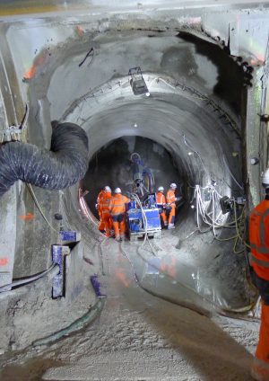
Running tunnel cross passages are short tunnels that connect the two running tunnels. Their purpose is to allow access from one tunnel to another in an emergency or for maintenance purposes. Some cross passages are deliberately placed at low points within the alignment so they can host drainage sumps and sump pumps. The Crossrail running tunnels were mined and constructed using TBMs and the cross passages were built after the running tunnels. They were all hand mined using a variety of temporary and permanent support measures determined by the geology and groundwater conditions.
The locations of cross passages were pre-determined and these locations were provided with special segment rings by the TBMs. These rings (‘opening sets’) were designed to temporarily support the openings made to construct the cross passage tunnel. These opening sets were either constructed from spheroidal graphite iron segments (on contracts C300 – Western Running Tunnels and C305 – Eastern Running Tunnels) or pre-cast concrete rings (contract C310 – Thames Tunnel) containing reinforcement cages (rather than fibre reinforcement).
Some cross passages in or close to permeable strata (parts of the Lambeth Group, the Thanet Sand Formation and the Chalk) containing groundwater under pressure required local depressurisation and/or dewatering. In some cases this requirement was assisted by larger scale dewatering undertaken by Crossrail (at the Limmo peninsula) or Canary Wharf Group (at Canary Wharf). Additionally dewatering provided at CP11 and CP13 also provided some assistance in dewatering/depressurisation at neighbouring cross passages. These relationships are set out in the table.
Cross passages are positioned between permanent shafts, portals and stations such that the spacing between opportunities to cross from one track to another is in the range 600m to 800m. In many cases the cross passages replaced permanent intervention and escape shafts that were initially proposed for Crossrail.
The following table summarises for each running tunnel cross passage:
- The relevant geology
- The construction methodology
- The nature of any temporary dewatering or depressurisation (surface or in-tunnel)
- The nature of any grouting
Ground freezing was not adopted at any of the cross passages.
Cross passages within stations and crossover tunnels are not covered by this report.
Running Tunnel Cross Passage Location Geology
HF – Harwich Formation
SU – HF Sand Unit
UMB = Upper Mottled Beds
LSB = Lower Shelly Beds,
LTB = Laminated Beds, LMB = Lower Mottled Beds,
UF= Upnor Formation
TS = Thanet Sand Formation
Contractor Construction methodology Local surface dewatering Assistance from remote deep aquifer dewatering In tunnel depressurisation Grouting CP1 & Sump West of Paddington London Clay B C300 BFK SCL (primary and secondary) for the cross passage and sump walls. Cast in situ RC for the collars, including the sump collar and for the sump base. No No No No CP2 & Sump Hyde Park – North West London Clay B and A3 C300 BFK SCL (primary and secondary) for the cross passage and sump walls. Cast in situ RC for the collars, including the sump collar and for the sump base. No No No No CP3 Hyde Park – Centre London Clay B and A3 C300 BFK SCL (primary and secondary) for the cross passage. Cast in situ RC for the collars. No No No No CP4 Hyde Park – East London Clay A3 and A2 C300 BFK SCL (primary and secondary) for the cross passage. Cast in situ RC for the collars. No No No No CP4A & Sump Between Bond St. and Tottenham Court Road London Clay A3 and A2, Lambeth Group UMB. C300 BFK SCL (primary and secondary) for the cross. Cast in situ RC for the collars, including the sump walls, collar and for the sump base. No No Yes No CP5 Grays Inn Lambeth Group UMB, LSB LTB and LMB with LTB Sand Channel C300 BFK SCL (primary and secondary) for the cross passage. Cast in situ RC for the collars. No No Yes No CP5A & sump Barbican Water bearing LTB sand channel in the face & above the crown
C305 DSJV Timber temporary works, SGI cross passage lining, cast RC collars and sump base. Pre-cast segmental rings used for the sump walls. No No Yes No CP6 & sump Spitalfields LTB sand channel in the face
C305 DSJV Timber temporary works, SGI cross passage lining, cast RC collars and sump base. Pre-cast segmental rings used for the sump walls. No No Yes – LTB sand channel No CP8 Stepney London Clay
C305 DSJV Timber temporary works, SGI cross passage lining, cast RC collars and sump base. Pre-cast segmental rings used for the sump walls. No No No No CP9 & sump West of Stepney Green LTB sand channel below the sump base
C305 DSJV Timber temporary works, SGI cross passage lining, cast RC collars and sump base. Pre-cast segmental rings used for the sump walls. No No Yes – LTB sand channel, for the sump only No Niche 3 & sump East of Stepney Green, Pudding Mill Lane Branch LTB sand channel above crown and UF/TS below invert.
C305 DSJV Timber temporary works, SGI cross passage lining, cast RC collars and sump base. Pre-cast segmental rings used for the sump walls. Yes – TS Yes – benefit obtained from concurrent CP11, CW and CP13 dewatering. Yes, LTB sand channel. No CP10 West of Limehouse LTB sand channel above crown and UF/TS below invert.
C305 DSJV Timber temporary works, SGI cross passage lining, cast RC collars and sump base. Pre-cast segmental rings used for the sump walls. No No Yes – LTB sand channel and UF/TS No CP11 & sump East of Limehouse UF & TS C305 DSJV Timber temporary works, SGI cross passage lining, cast RC collars and sump base. Pre-cast segmental rings used for the sump walls. Yes – Chalk and TS Yes – benefit obtained from concurrent CW pumping Planned as optional in the TS for the sump construction and required in practice
No CP12 West of Canary Wharf Station TS C305 DSJV Timber temporary works, SGI cross passage lining, cast RC collars and sump base. Pre-cast segmental rings used for the sump walls. No Yes – benefit obtained from concurrent CW pumping.
Yes – TS No CP13 & sump Blackwall TS C305 DSJV Timber temporary works, SGI cross passage lining, cast RC collars and sump base. Pre-cast segmental rings used for the sump walls. Yes – TS & Chalk Yes– benefit obtained from concurrent pumping at Limmo and CW.
Yes – TS
No CP14 Near East India Dock Basin HF SU in upper face and above crown C305 DSJV Timber temporary works, SGI cross passage lining, cast RC collars and sump base. Pre-cast segmental rings used for the sump walls. Yes – HF SU Yes – benefit obtained from concurrent pumping at Limmo and CP13.
Yes – UF & TS
Yes CP15 Near Royal Victoria DLR Station HF SU below invert
C305 DSJV Timber temporary works, SGI cross passage lining, cast RC collars and sump base. Pre-cast segmental rings used for the sump walls. No Yes – Limmo Yes – HF SU No CP16 North Woolwich Chalk in the CP face with water bearing RTD above. C310 HMJV Cross passages: SCL temporary lining, cast in-situ RC permanent lining No No No Fissure and in- tunnel grouting of the Chalk from the surface CP17 & sump.
Under the River Thames Chalk in the CP face with water bearing Alluvium above. C310 HMJV Cross passages: SCL temporary lining, cast in-situ RC permanent lining No No In-tunnel passive drainage provided within the fissure grouted Chalk In-tunnel fissure grouting of the Chalk CP18 & sump.
Between Plumstead and Woolwich Chalk in the CP face with water bearing TS & RTD above. C310 HMJV Cross passages: SCL temporary lining, cast in-situ RC permanent lining No No No In-tunnel fissure grouting of the Chalk CP19 Plumstead Chalk in the CP face with water bearing RTD & TS above. C310 HMJV Cross passages: SCL temporary lining, cast in-situ RC permanent lining No No No Jet grouting from ground level to 1m in to the Chalk. Fissure grouting of the Chalk below this. -
Authors
John Davis EurGeol CGeol MSc DIC - Geotechnical Consulting Group
John was seconded to the Chief Engineers Group within Crossrail from Geotechnical Consulting Group LLP from 2009 until July 2016.
Within the Chief Engineers Group John was responsible for all Crossrail geotechnical matters east of Farringdon. Whilst at Crossrail John was also closely involved with the production of Geotechnical Baseline Reports for all the major Civils contracts. Prior to Crossrail John spent 20+ years as a geotechnical designer working on a diverse range of structures across the world, these included deep basements, embankments, tunnels, slopes and retaining walls. John was seconded to London Underground for a couple of years in the mid 90’s where he led a research programme on the impact of rising groundwater on the tube network.

