Crossrail Sprayed Concrete Lining Depressurisation at Stepney Green Caverns
Document
type: Technical Paper
Author:
David Harris BSc MSc DIC CGeol FGS, Andrew Davis BSc, MSc, C Geol, FGS, Emilio Linde BSc MSc DIC EurGeol FGS, ICE Publishing
Publication
Date: 03/11/2014
-
Read the full document
Introduction
Crossrail is a new railway currently under construction in London and when completed will significantly reduce journey times across the capital. It includes approximately 10 km of Sprayed Concrete Lining (SCL) tunnels at station, ventilation shaft and junction locations. One of the largest of these tunnels is being constructed at Stepney Green, East London, to facilitate construction of a sub-surface junction. This will allow Crossrail trains from Maidenhead and the west to travel to Shenfield and Woolwich in the east. The excavation and installation of primary sprayed concrete lining at Stepney Green was completed in August 2013.
The east- and west-bound cavern crowns lie 17 m and 21 m respectively below ground level in a constrained urban site and are situated within the London Clay and underlying Lambeth Group formations. The Lambeth Group is a variable series of clays, silts and sands and the higher permeability sands contain high pore pressures which are hazardous to SCL construction (CIRIA, 2004). Depressurisation of these high pore pressures was crucial to the safe construction of the caverns and compliance with the zero harm Crossrail ethos.
On the Crossrail project a distinction was made between use of the terms dewatering and depressurisation in order to facilitate discussions with third parties regarding the likely impact of any measures affecting groundwater. Dewatering was considered as applying to any pumping undertaken within the Lower Aquifer, with wider environmental implications, and depressurisation for pumping undertaken in the overlying Lambeth Group. For the purposes of consistency the term depressurisation has been used in this paper.
The SCL permanent works were designed by Mott MacDonald (Contract C121) with the construction undertaken by the contractor, Dragados Sisk Joint Venture (DSJV) under Contract C305. Temporary works design was provided to DSJV by OTB Engineering with the well systems being provided by WJ Groundwater.
Geology
The geology at Stepney Green is typical for that of east central London; comprising of a sequence of strata from Thanet Sand, the complex Lambeth Group strata, Harwich Formation and the lower A2 & A3 units of the London Clay. A summary is provided in Table 1 and a longitudinal section as Figure 1.
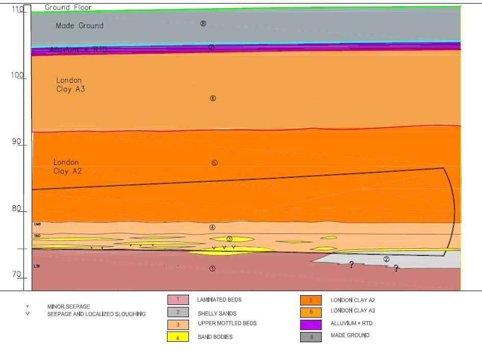
Figure 1 – Schematic geological section along the westbound cavern
The eastbound SCL cavern is located predominantly within the London Clay A2 unit with Upper Mottled Beds at invert level. The westbound cavern is approximately 4 m deeper, causing the excavation to be within London Clay, Harwich Formation, with up to 4 m of Lambeth Group below axis level.
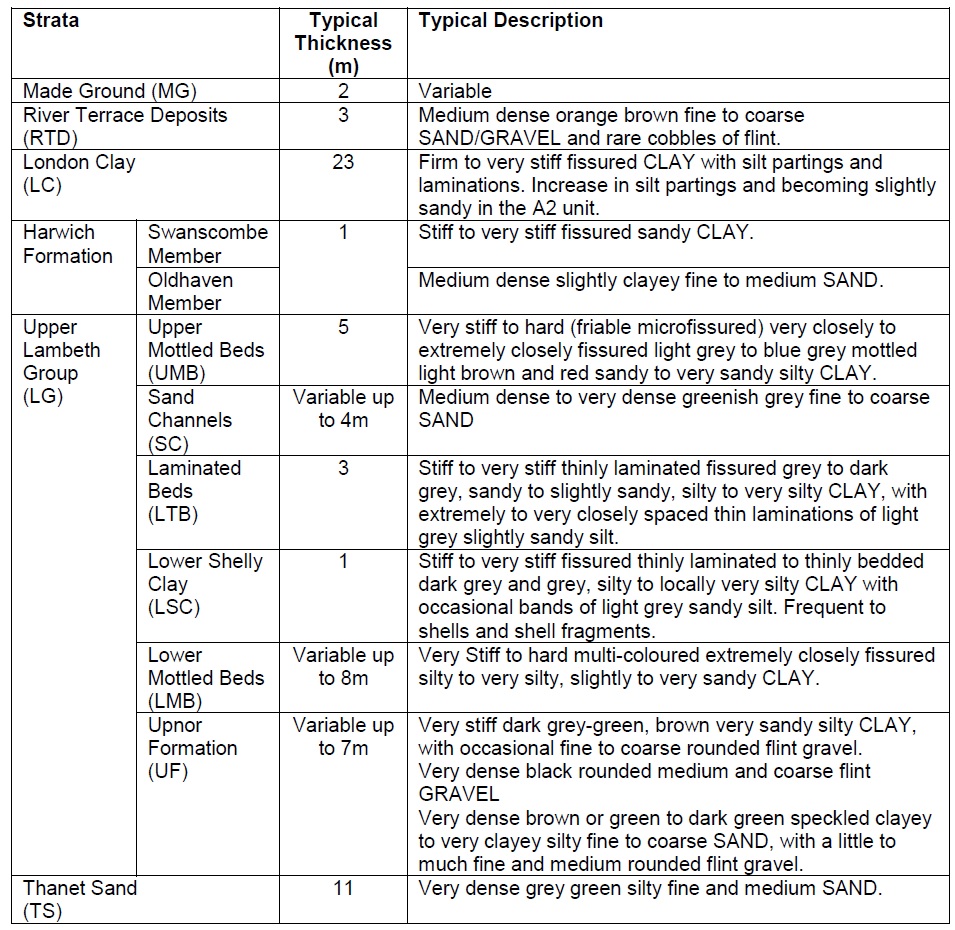
Table 1 – Summary strata at Stepney Green
Within the Lambeth Group there occur relict sand channel deposits related to the paleo-environment present during the geological period of deposition, representing a series of meandering channels in an estuarine type environment. These channels vary in frequency, width, depth, length and infill material and, as a result, are spatially unpredictable and therefore problematic to identify by Ground Investigation (GI) with any degree of certainty. There are examples of large extensive channels proven by Crossrail ground investigations, such as below Bond Street station where identification and extrapolation is more certain. The size of channels identified at Stepney Green however tend to be thinner, typically to a maximum thickness of 4 m, less extensive and encountered variably throughout the Lambeth Group. It was known from the GI that to the west of Stepney Green there was a thick persistent sand unit but towards the east, where the major caverns were to be excavated, the sand units became thinner and laterally impersistent.
Groundwater
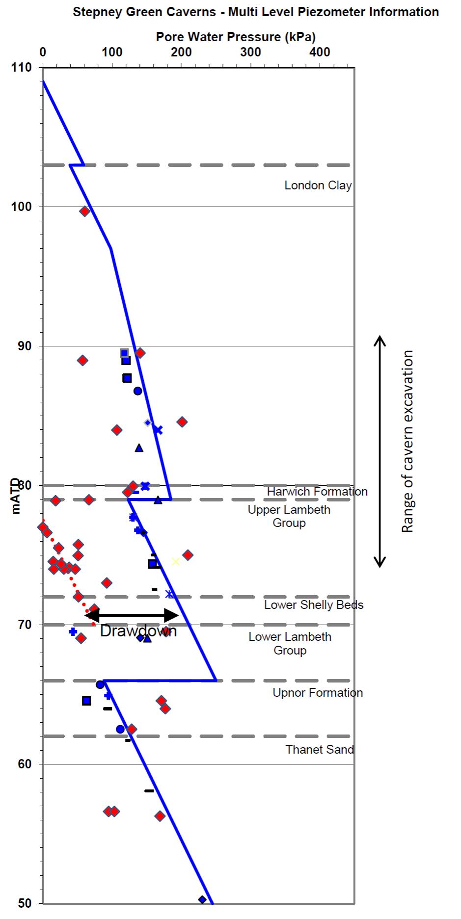
The groundwater profile at Stepney Green (figure 2) is typical for the London area comprising of an upper aquifer located in the superficial deposits and a lower aquifer within the Chalk, Thanet Sand and Upnor Formation. The historical effects of groundwater abstraction from the Lower Aquifer has resulted in an underdrained profile with pore pressures within the Thanet Sand and Upnor Formation being much lower than those above in the London Clay and Upper Lambeth Group. The pore pressures within the SCL excavation depth range were variable and related to the underdrainage effects with maximum values of approximately 180 kPa at the base of the London Clay dropping to 120 kPa at the top of the Lambeth Group. The expected groundwater pressures to be encountered in any sand channels in the vicinity of the SCL works was therefore considered to be in the range 120 kPa to 150k Pa.This detailed profile was able to be determined due to the inclusion of several high quality multi-point monitoring systems included within the GI.
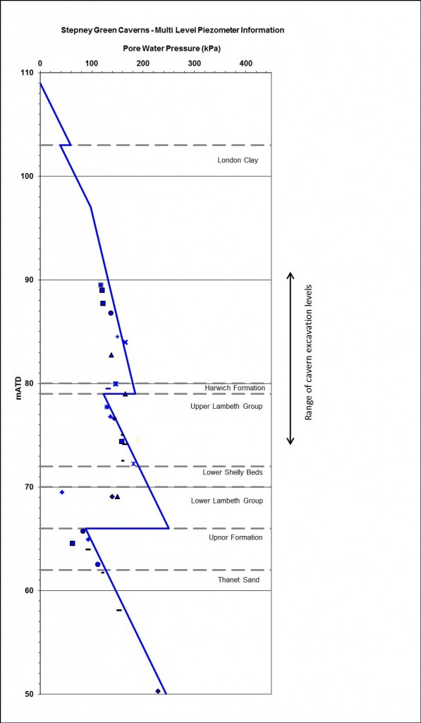
Figure 2 – Muliti-point piezometer readings and adopted pore pressure profile.
Ground Investigation
Due to the relatively long planning stages of Crossrail, four phases of ground investigation were undertaken at Stepney Green over an eight year period to obtain geotechnical and groundwater information. The ground investigations included cable percussion and rotary boreholes, two in-situ pressuremeter testing boreholes and concluded in the final phase with a pumping test within the Lambeth Group. A total of 32 boreholes were drilled within 100 m of the proposed cavern locations.
Groundwater monitoring installations are summarised in Table 2 and consisted of conventional 25mm Casagrande piezometers, 50mm standpipes, vibrating wire piezometers, Continuous Multichannel Tubing (CMT) and a Multi-Port Sampling System (MPSS). Construction of groundwater monitoring installations was carefully supervised with none of the piezometers exhibiting erroneous hydraulic connectivity between aquifers. The multi-port systems proved particularly useful, as well as economic despite initially longer installation times.
Type Total 19mm piezometer 22 50mm standpipe 5 150mm standpipe (well) 3 Vibrating Wire 14 Continuous Multichannel Tubing system 12 Multi Port Sampling System 6 Total 62 Table 2 – Summary of groundwater installation details at Stepney Green
Pumping test
A pumping test was specified to determine the permeability of sand channels within the Lambeth Group and to provide data to allow design of the depressurisation requirements. The pumping test comprised three pumping wells with 7 days pumping and 7 days recovery monitoring. This was considered to more closely reflect the likely actual multiple pumping set up to be used during construction, rather than using a traditional single pumped well. The three pumping wells comprised 150mm slotted pipe constructed in 300 mm diameter boreholes. Each well had a screen length of between 8 m and 8.5 m length through the Upper Mottled Beds and Laminated Beds including sand channels. The wells terminated in the Lower Shelly Beds which were below the invert levels of the two caverns. The Harwich Formation was sealed off from the well screens to avoid potential misleading results.
Monitoring of piezometers, standpipes, CMT and VW piezometers was undertaken prior to and during the test at intervals in accordance with BS EN ISO 14686:2003. These were supplemented by manual monitoring of key installations, to ensure that in the event of a datalogger breakdown, manual data could be used to supplement the results.
A series of three step tests were undertaken to determine the maximum yield of each well. A constant discharge test was then undertaken using three submersible pumps. The headworks of the three wells were sealed and a vacuum pump used to improve yield. The test commenced with one well pumped at approximately 1litre/second with a vacuum applied. After one day a second well also commenced pumping under vacuum, increasing the combined flow rate to 1.3 l/s. Finally, the third well commenced pumping under vacuum, with a slight reduction in flow rate. Pumping stopped after 7 days at a final combined flow rate of 1.17 l/s. The maximum yields obtained during the test were from the three separate wells were:
First well 1.06 l/s with partial vacuum of -7.3 m H2O,
Second well 0.58 l/s with partial vacuum of -8.1 m H2O and,
Third well 0.45 l/s with partial vacuum of -6.0 m H2O.The maximum drawdown within the Upper Lambeth Group achieved at the end of the 7 day pumping period was typically 8m at a distance of 10m, and 3m at a larger distance of 85m. There was insignificant drawdown in the underlying Lower Aquifer.
The wells took approximately 10 days to recover to pre-test levels, with the majority recovering within the first 7 days. The test showed that the sand channels generally had connectivity within the Lambeth Group, which provided confidence in the ability to successfully depressurise the Lambeth Group from surface wells. As expected there was insignificant drawdown in the overlying River Terrace Deposits or London Clay. Although the pumping test was not anticipated to produce surface settlement due to the limited duration and relatively small volumes of discharge, precise levelling was undertaken to demonstrate this, which could subsequently be used to assure adjacent stakeholders.
The pumping test results were analysed using a range of methods. The main method of analysis was the Cooper-Jacob Well Field Method (Kruseman and de Ridder, 1994) due to the pumping rate increasing in steps as the second and third wells were added. The conventional Theis curve fitting method was also used and the Theis’ recovery and the steady state Theim’s method were used (Kruseman and de Ridder, 1994). The results of the analysis indicated a transmissivity between 5 to 12 m2/d (permeability of 6×10⁻⁵ to 1×10⁻⁴m/s) and a storativity of 7×10⁻⁴ to 6×10⁻³.
SCL Ground Related Risks
SCL tunnel excavation is undertaken by spraying concrete directly onto exposed excavated ground, forming an immediate bond with the strata. The lining can follow complex profiles and layouts, in-fill over-break, and forms a strong, durable and watertight shell. As such it is an ideal method for the construction of complex geometrical layouts such as the Stepney Green caverns. The method does however require that the excavated ground remains stable in order that the sprayed concrete can be applied. Although the geology and groundwater conditions at Stepney Green are not unusual for east London, SCL introduces greater ground risk than conventional bored tunnelling. The need to control groundwater ingress and pressures where sandy materials occur in an open face or at invert is very important if stability, and safe conditions, are to be maintained prior to application of the sprayed concrete.
If the groundwater pressures at the face of the excavation are not reduced adequately they will cause instability of sand layers, resulting in the sand running into the excavation. If sand comprises a significant proportion of the face then direct face instability can occur. In situations where minor sand/silt strata occur (such as laminae) the wash in of soil may cause local undermining of the face and subsequent indirect instability. Any such loss of material from the face could trigger a fall of ground from the face, overbreak and cause additional settlement. Where the invert is within sandy material, the presence of elevated pore pressures can lead to the development of running sand conditions. In addition to stability concerns, groundwater ingress can result in poor working conditions which are unacceptable on health and safety grounds.
The extent of the risk and the form of the mitigation depend on a number of variables:
• The size of sand units that control the quantity of potentially stored groundwater;
• Their permeability which controls the rate of water inflow;
• Their ability to recharge which controls the time for which inflow may occur,
• The magnitude of the pore water pressures present which affects the amount of inflow
• The location of the sand channel in relation to the tunnel excavation profileThe risk of instability at Stepney Green was particularly hazardous due to the unusual size of the excavations required to construct the 17m diameter caverns.
Depressurisation Strategy and Design
Preliminary Design
Depressurisation works were considered as temporary works and the responsibility for the design and implementation lay with the contractor. However in order that the tender process could be assessed on an even basis, the designer derived an indicative preliminary design for pricing purposes. The successful contractor was then responsible for taking forward the design to suit their own assessment and programme of work to satisfy a performance specification.
The key aims of the preliminary depressurisation strategy were to address both the unpredictable nature and location of the water bearing strata, and the high pore pressures that would influence the practicality of maintaining safe excavations. To adequately reduce the level of risk there was a need to undertake SCL excavation with a degree of confidence that unexpected water bearing sandy materials were unlikely to be encountered. In order that the risk could be maintained As Low As Reasonably Practicable (ALARP) there was a requirement that construction investigation works were comprehensive.
To address that risk an extensive investigation and depressurisation scheme was developed combining both surface and in-tunnel works. The Stepney Green worksite is small and the adjacent third party land (including an urban farm, protected archaeological area and an all- weather sports facility) was not considered appropriate for undertaking construction based activities. The potential for surface depressurisation was optimised where possible by the inclusion of inclined wells drilled from within the worksite but terminating at tunnel level beyond the site. The potential to maximise use of surface well sites was therefore constrained and it was therefore considered that it was not possible to confidently identify and depressurise all water bearing materials by surface works alone.
Based on previous experience a maximum pore pressure of 100 kPa was adopted in the indicative designs as the limit at which sub-surface in-tunnel wells could practically be installed. This value was related to the difficulty of controlling groundwater ingress and bore stability during drilling, and the ability to subsequently install a well within the bore. Given the expected pore pressure values of up to 150 kPa it was considered that pore water pressures would need to be reduced, as a minimum, to less than 100 kPa by surface wells in advance of SCL tunnel excavation.
As it was considered that surface wells alone could not produce a dry excavation, it was envisaged that additional wells would be installed from within the shaft and/or tunnels. As the sand channels were not accurately known it was considered that a robust array of investigatory probing would be taken ahead of the advancing SCL face to identify any groundwater bearing strata. Wells would then target those locations where groundwater was identified. The number of wellpoints and wells required, and the time required to obtain the necessary depressurisation, would depend on the extent of the water bearing materials, their permeability, pore water pressure and amount of recharge potential. It was expected that different drilling patterns and numbers of probe holes would relate to the different excavation sequences.
The indicative tender design comprised a total of 25 surface wells and 140 in-tunnel gravity and vacuum wells. The surface well spacing was based on a typical 8 m drawdown cone being achieved around each well such that individual well spacing was 16 m. Surface wells were anticipated to comprise pumped and/or ejector wells, depending on the permeability of the strata to be depressurised. The combined depressurisation was considered to occur as a temporary “moving front” of depressurisation ahead of the excavation face, with the wells being redundant once the primary lining has been completed and gained adequate strength.
Contractor’s Design
The contractor reviewed the preliminary design and revised the strategy to reduce the potential need for in-tunnel depressurisation measures by maximising the surface well layout. The intention was to reduce water levels to as low as possible from surface such that smaller quantities of in-tunnel measures were required. The increase in surface well coverage was possible due to the greater control that the Contractor had upon the location and timing of site access constraints. In-tunnel depressurisation mitigation measures were retained as part of the overall design to supplement the surface depressurisation measures. This revised approach was beneficial as it would reduce programme critical and expensive delays to tunnel excavation works by reducing the number of in-tunnel wells required.
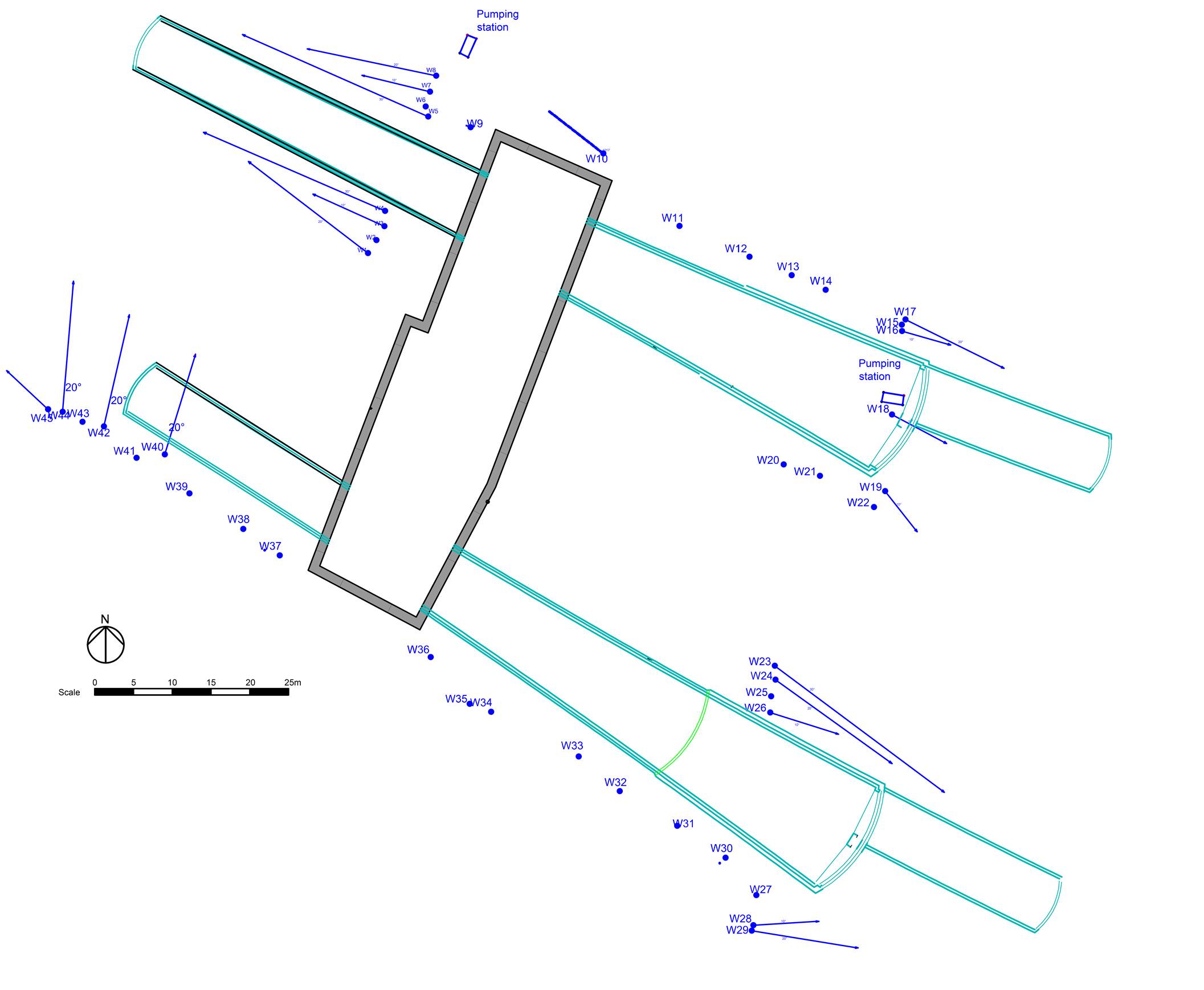
An ejector spacing of approximately 8 m was implemented based on the pumping test data, experience of working in these conditions at other sites, the constraints imposed by surface access and the application of engineering judgement. This spacing was approximately half that provided in the preliminary design. Ejectors were located in two separate rings to surround the caverns where possible. The location of the ejectors depended upon the layout of the site and other existing surface constraints. Inclined wells (up to 30 degrees from vertical) were retained in the layout to achieve the desired coverage outside the boundaries of the site. Figure 3 illustrates the design layout of the scheme.

Figure 3 – Surface well layout plan
The main features of the implemented depressurisation scheme were:
• No. of ejectors: 45 No.
• Depth: 40 m (110 to 70 mTD)
• Vertical installations: 27 No. Inclined at 10 deg: 7 No. Inclined at 20 deg: 8 No. Inclined at 30 deg: 3 No.
• Bore size: 200/250 mm nominal.
• Response zone: 70 to 83 mTD.
• Pumping Ejectors operated from a surface pumping station
Figure 4 – Pore pressure reduction achieved by surface wells
Following commissioning of the surface ejectors a drawdown equivalent to a pore pressure reduction of 140 kPa was observed in the piezometers as shown in figure 4. The monitoring indicated that:
• Most of the piezometers in the Upper Lambeth Group achieved an average drawdown of approximately 14 m (i.e. a pore pressure reduction of 140 kPa).
• Piezometers in the Upper Lambeth Group located close to the base of the London Clay were not significantly affected by the pumping. The likely cause of that was that those piezometers were installed in the Upper Mottled Beds, a cohesive material and therefore of low permeability.
• There was a certain degree of scatter in the drawdown data meaning that the effectiveness of the pumping was variable confirming the variability of the sandy layers within the Lambeth Group.
The average drawdown achieved was considered sufficient for the Eastbound Cavern to be constructed without subsequent in-tunnel depressurisation works, as that was to be constructed in London Clay. However, the drawdown was not sufficient for the deeper Westbound Cavern for which groundwater levels remained typically 1m above invert level. In order to achieve the desired drawdown in the Westbound cavern additional drawdown from within the tunnel was needed.
Initial trials were undertaken by the contractor using wells drilled from the shaft prior to SCL excavation and well layout proposals were derived as summarised in figure 5. Different well layout proposals were derived to suit the different excavation sequences required. Due to the Lambeth Group being only encountered below tunnel axis level, no measures were required for the excavation of the initial top heading, additional measures only being required for subsequent bench and invert excavations.
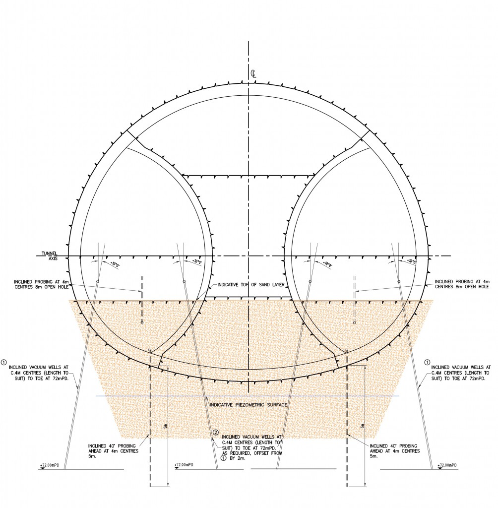
Figure 5 – In-tunnel depressurisation mitigation
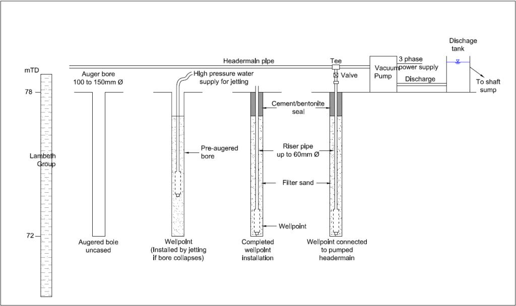
The sequence of in-tunnel wellpoint installation is shown in figure 6 with the main features being as follows:
- Approximately 105 No. Wellpoints were installed in 90mm auger-drilled holes
- Wellpoints consisted of a 38mm Poly Vinyl Chloride (PVC) pipe with a 1m to 2m bonded sand filter screen (54 mm OD)
- Wellpoints were of variable lengths depending on geology/elevation and angle.
- 25 mm PVC pipework was used to carry discharge water along the tunnel.
- A V-notch tank was used to measure the flow of the system.

Figure 6 – Typical in-tunnel well installation and set up
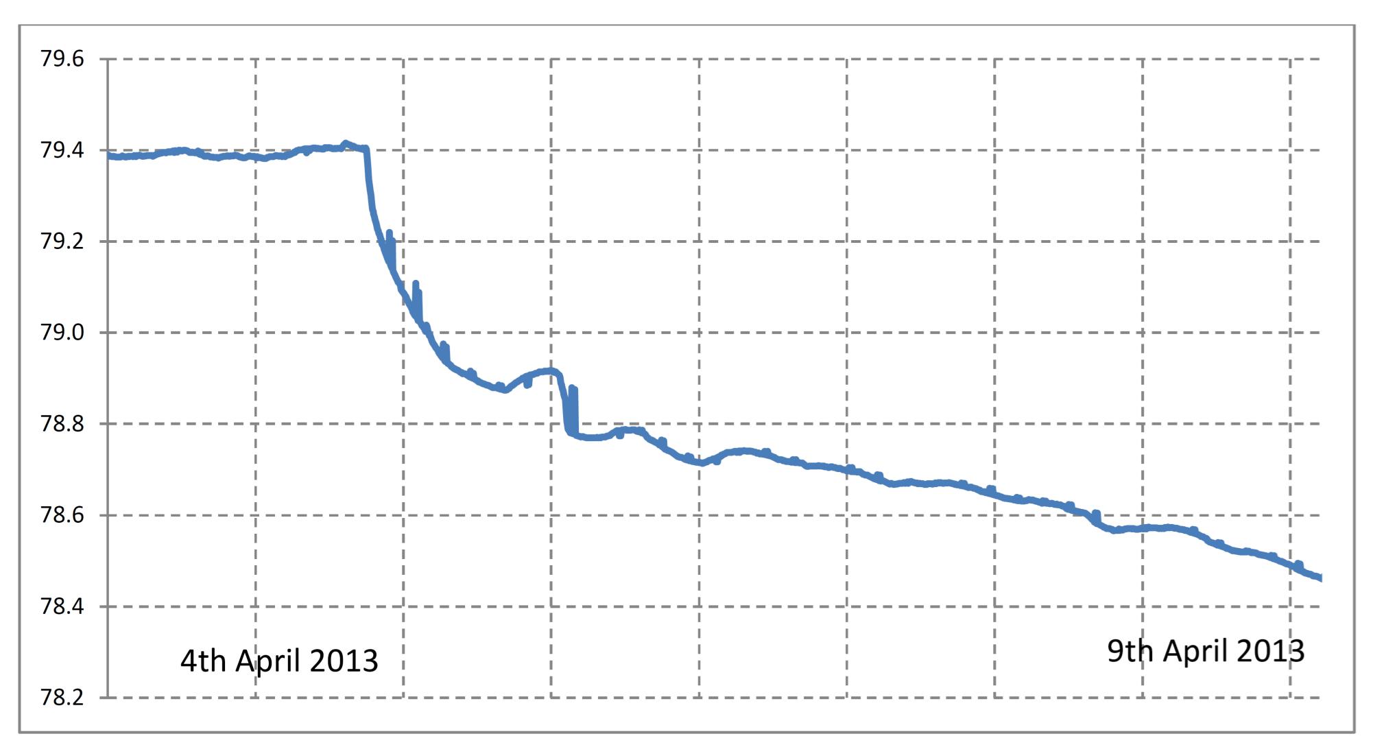
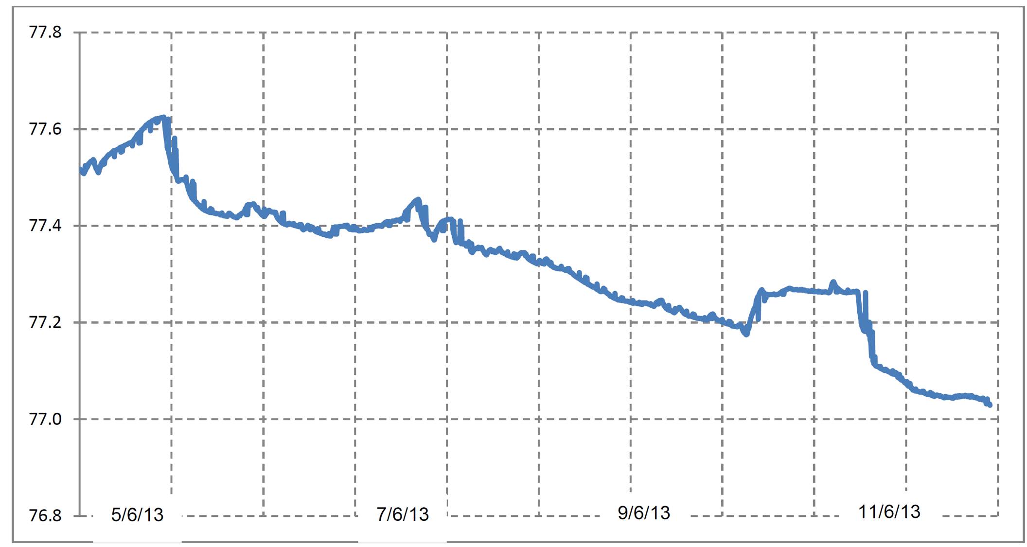
The inclusion of the in-tunnel wellpoints resulted in the depressurisation occurring as expected as a temporary “moving front” of depressurisation with the tunnel wellpoints being installed as the excavation progressed. Figure 7 shows an example of this front of reducing water level as the excavation approaches a piezometer at the end of the Westbound Cavern.

Figure 7 – Example of pore pressure reduction achieved by additional in-tunnel wells
Managing, monitoring and performance during construction
Once installed and operational, a critical aspect of the depressurisation system was the continual monitoring of the piezometric levels, the maintenance of the system and management of the information. Separate strategies were developed for the surface and in-tunnel depressurisation measures.
Surface depressurisation system
Maintenance
The surface system consisted of 45 ejectors divided in two stations with three pumps in each: two duty pumps and a third one acting as a back-up in case of mechanical failure. In case of a power failure each station included stand-by generators. Daily maintenance was carried out by a resident operator with checks of the performance (flows, pressures, condition of the pipes etc.). To provide constant support to the 24/7 tunnelling operations an operator was on call to attend any failure in the system during night shifts.
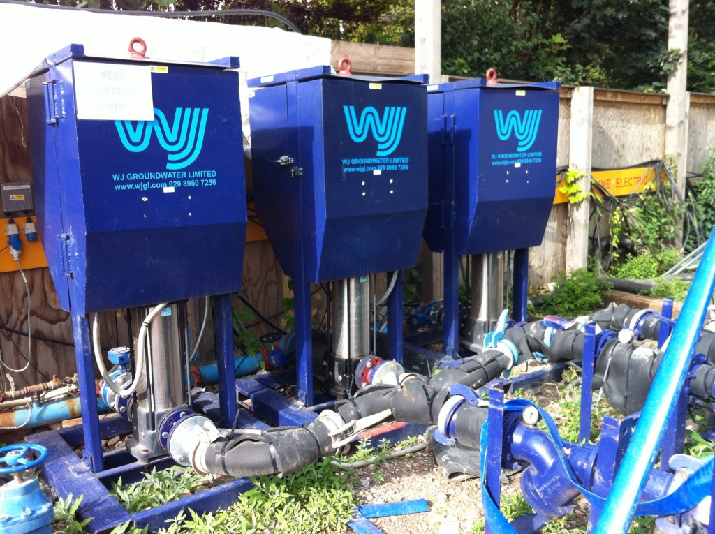
Figure 8 – Multiple surface well pump arrangement
An automated communication system was set up such that any loss of pressure or power failure would immediately be notified by text message to the dewatering operative and the SCL works “Person In Charge”. Additionally a sound alarm would alert the rest of the site personnel to the situation. To ensure safety a “Safe stop” condition would be implemented in the SCL works, with removal of personnel, until remedial action had been taken to re-establish acceptable pore pressures.
Periodic maintenance activities included the removal of deposited iron crust caused by the presence of Gallionella ferruginea bacteria that affected the performance of the ejectors. The gradual reduction in ejector efficiency caused by these materials was noticeable from the piezometer records.
Monitoring & Management
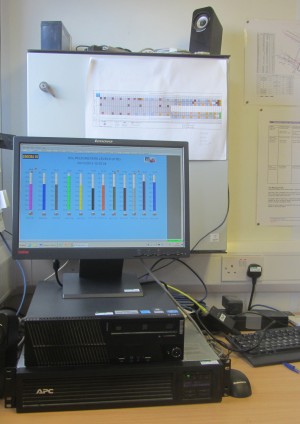
For monitoring the drawdown 12 new piezometers were installed with piezometric level readings taken every two minutes and automatically sent to the Real Time Monitoring Centre (RTMC), where values were instantly visible. A back up unit guaranteed that the RTMC was always operational. Several gradational trigger levels were set to alert site personnel of unexpected changes of water levels that could affect the safety of SCL activities. If a piezometer reading was above a trigger level a text was sent to the dewatering operative and the SCL works “Person In Charge”. Additionally a sound alarm would alert the rest of the site personnel. To ensure safety a “Safe stop” condition would be implemented in the SCL works, with removal of personnel, until remedial action had been taken to re-establish acceptable pore pressures.
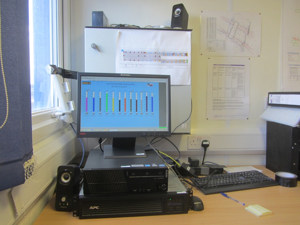
Figure 9 – Real Time Monitoring Centre
A daily review of the piezometric levels was carried out at the Shift Review Group meeting (SRG) in order to confirm the acceptability of continued excavation procedures.
In-tunnel depressurisation system
Maintenance
Similarly to the surface system, daily checks were carried out on the in-tunnel system. However, during excavation difficulties were encountered in achieving a completely dry excavation and a series of reviews and upgrades were undertaken to improve efficiency and performance.
First Upgrade
As a consequence of the presence of sandy material at the base of the invert together with water levels 500 mm above excavation level, some sloughing was observed during the excavation. However, where a sand/clay boundary was encountered in the face some residual water was typically encountered, even when the depressurisation measures appeared to have worked satisfactorily.
On occasions, contingency measures were required (sump pumps and caissons) which led to delays in construction progress. As invert level reduced as the westbound cavern excavation progressed away from the access shaft, there was an increasing risk of encountering “quick sand” phenomena. Due to that increasing risk the in-tunnel depressurisation system was reviewed in order to improve its performance. Several actions were identified and implemented:
• Lowering the vacuum pipework to reduce the suction head of the system.
• Increasing the diameter of the pipework to increase the flow. It was increased from PVC 25mm to PVC 50mm.
• Increasing the length of the porous filter in the well from 1m to 2m.
• New wells were installed with a layer of gravel to allow some ‘breathing’ that could help clean the screens and reduce clogging of the system.
• Back-flushing existing wellpoints to improve their operating efficiency.When the above actions were completed, an immediate effect was observed in the piezometers resulting, as shown in figure 10, in an additional drawdown of 500mm.
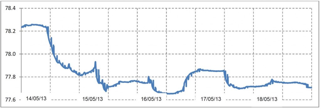
Figure 10 – Pore pressure reduction achieved by additional in-tunnel measures (First Upgrade)
Second Upgrade
After completion of the first side drift of the westbound cavern, it was considered necessary to upgrade the depressurisation system once again to further improve performance and reduce groundwater level for the excavation of the second side drift and central pillar. Several actions were implemented as follows:
• Installation of new pipework and lowering of the pipework to reduce the suction head of the system.
• Upgrading the pipework from 50 mm PVC pipe to 100 mm steel pipe.
• New Geho piston pumps installed to replace the low flow DM-Vex vacuum pumps.
• The well filter specification in fine soils is always a compromise between meeting the conflicting requirement to keep out fines and let in water. As the amount of fines were not significant more permeable ones were specified for the wells. Figure 11 shows the revised wellpoint construction.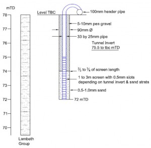
Figure 11 – Revised wellpoint arrangement
These changes were initially tested in three trial wells the improved drawdown being demonstrated by the Figure 12. The changes ensured the remaining inverts of the westbound cavern were completed safely and without further requirements to reduce groundwater.
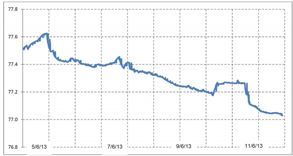
Figure 12 – Pore pressure reduction achieved by additional in-tunnel measures (Second Upgrade)
Monitoring and management
The performance of the tunnel wellpoints was monitored by using un-pumped wellpoints as equivalent standpipe piezometers. This allowed the monitoring location and pumped wellpoints to be altered to suit the progress of the works. In addition, where required, dedicated piezometers were installed to 1 m below invert. Real time information from the piezometers was used to check trends and detect problems in any of the pumps. The invert excavation was the most critical part of the tunnel in terms of water bearing materials so a hold point was implemented within the excavation procedures effectively acting as a “permit to dig”. The hold point required checking of water levels in the closest standpipe prior to the excavation, with the potential for revision of the depressurisation system and adoption of additional mitigation measures.
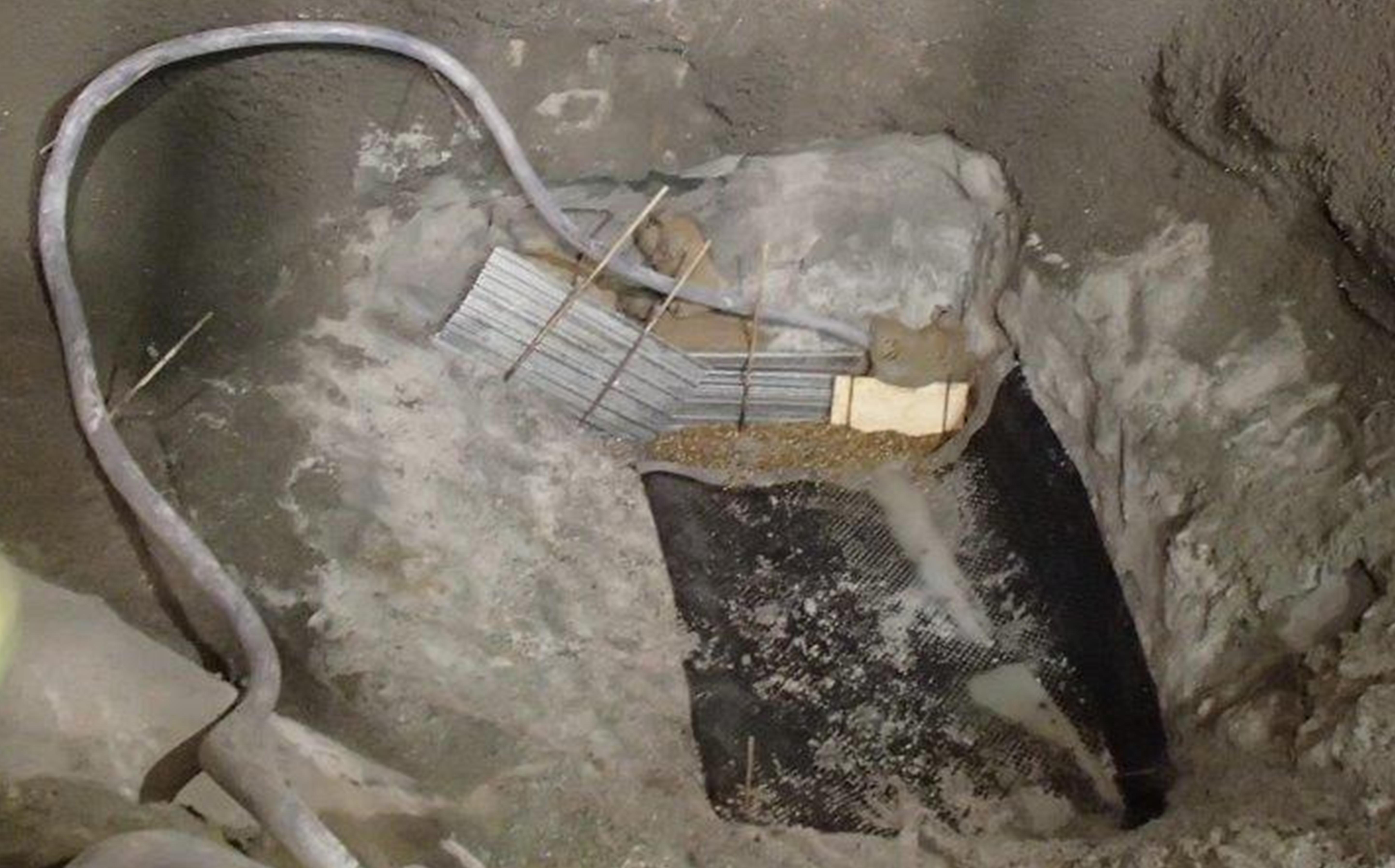
It was anticipated that, given the variability of the permeability and location of the sand channels, the design would have to be locally altered. Figure 13 illustrates an example where several contingency measures were implemented to aid in achieving a dry excavation. The need for such measures was infrequent and eliminated by the upgraded maintenance measures described above, improving both safety and efficiency.
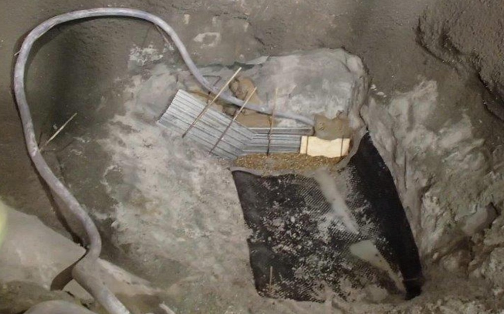
Figure 13 – Additional contingency measures
Conclusions
The ground investigations, pumping test, designer’s outline depressurisation design and final contractor’s depressurisation design allowed the safe SCL construction of Stepney Green caverns in the Lambeth Group. An accurate ground model of the Stepney Green site was essential in understanding where to target investigations and to understand the variability of water bearing sandy materials in the Lambeth Group within which the deeper westbound cavern would be excavated. Close supervision and accurate measurement of pore pressures combined with use of multi-port piezometers ensured the groundwater data was reliable to inform the depressurisation plan.
Connectivity between Lambeth Group sand channels was demonstrated by both the pre-construction pumping test and by the use of surface ejectors and in-tunnel wellpoints. This was a key factor in being able to successfully use the contractors strategy of increased surface wells demonstrating the benefit of the GI work undertaken.
Key lessons learned included:
• Multi-port piezometers can be installed successfully allowing a reduction in the overall number of boreholes in a GI whilst providing reliable data for design purposes.
• Interconnectivity can exist between Lambeth Group sand channels, even if they are small and apparently separated by cohesive material.
• Adjustments and improvements to in-tunnel wellpoints such as increasing discharge pipe diameters can rapidly improve drawdown.
• Regular cleaning of ejectors rapidly improves drawdown.
• A certain residual amount of groundwater in Lambeth Group sandy materials can be expected, even when depressurisation appears to be successful.
• The drawdown response varied in relation to sand channel permeability, interconnectivity and morphology.
• The construction vindicated the requirement for a multi-level depressurisation approach using both surface and in-tunnel wells.
The use of automated instrumentation and communications in a real time context was successful in providing a robust safe action plan to forewarn of potential problems with the system.
The overall success was in part a result of the collaboration shown between the various parties in sharing knowledge of both the original design intent, the perception of the risks and the practical limits of implementing the systems. The knowledge sharing was aided by the ability to ensure continuity of personnel, with staff involved in the original GI’s and pumping test being involved on site throughout construction. The significant improvements in depressurisation achieved with relatively minor changes to the system set-up also demonstrated the benefit of using experienced sub-contractors familiar with local conditions. The efficiency of the operation was such that the daily SCL advance rates improved from the programmed 0.75m/day to 1m/day.
Acknowledgements
The authors would like to acknowledge Crossrail, Dragados –Sisk Joint Venture, OTB Engineering, Mott MacDonald, W. J. Groundwater, ESG Ltd (formerly Soil Mechanics Ltd.), Geotechnical Consulting Group and Miguel Mucientes, formerly of Mott MacDonald, who undertook the pumping test analysis.
References
BS EN ISO 14686 (2003). Hydrometric determinations – Pumping tests for water wells – Considerations and guidelines for design, performance and use. BSI, London, UK.
CIRIA C583 (2004). Engineering in the Lambeth Group. CIRIA, London, UK.
Kruseman GP and de Ridder NA (1994) Analysis and evaluation of pumping test data. IILRI, Wageningen, Netherlands. -
Authors