Design and construction of a hand mined Tunnel
Document
type: Technical Paper
Author:
Christopher Sumsion, Gavin Roche, Thomas Brown, ICE Publishing
Publication
Date: 31/08/2016
-
Read the full document
Notation
AADT Arup Atkins Design Team ALARP As Low As Reasonably Practical AP1 Link Passage between the London Underground and Crossrail Stations at Bond Street BFK Bam Ferrovial Kier Joint Venture BSSU Bond Street Station Upgrade C121 Crossrail Spray Concrete Lining Design Contract C122 Crossrail Bored Tunnels Design Contract C410 Crossrail Bond Street Station Tunnelling Contract CAD Computer Aided Design CI Cast Iron ECI Early Contractor Involvement HAVS Hand Arm Vibration Syndrom LU London Underground OTB BFKs Temporary Works Designer RFI Request for Information SCL Sprayed Concrete Lining SGI Spheroidal Graphite Iron UC Universal Column UK United Kingdom Introduction
A new link passage, AP1, between the new Crossrail station and the existing London Underground (LU) station at Bond Street was required to allow easy pedestrian access between the two stations and hence relieve congestion at surface level and reduce passenger journey times. To enable this, an existing ventilation tunnel servicing the Central line needed to be tunnelled through as the area below ground was particularly congested. As a result, the ventilation required for the Central line tunnels required re-routing. A diversion tunnel was considered the best solution. These structures can be seen in Figure 1.0.
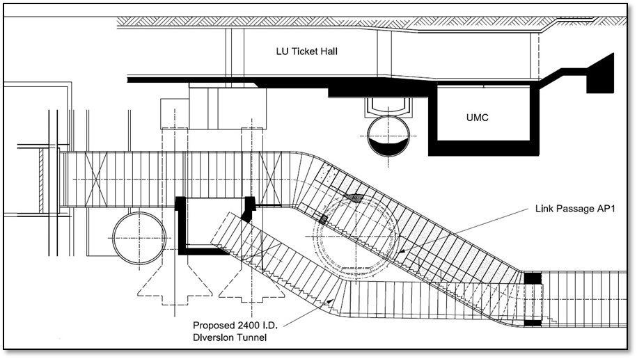
Figure 1.0 – Section view of the link passageway and diversion tunnel This work was programme critical to the opening of the new Crossrail Station. Therefore if this scheme had not demonstrated it could meet key milestone dates it would have been necessary to postpone construction until after the main Crossrail works. Completing these works post Crossrail would have increased costs significantly and presented additional challenging arrangements as well as inconveniencing passengers and pedestrians in the Bond Street area. Alternative schemes were not considered practical because they were less energy efficient and would require significant changes to the Crossrail Act and Environmental statements.
Initially the design and construction of the new ventilation tunnel was to be carried out by LU, but due to the programme requirements outlined above, the work was moved into the Crossrail scheme. The construction and design were awarded to C410 (Bam Ferrovial Kier Joint Venture) and C122 (Arup Atkins Design Team) respectively as a variation. Due to the complex nature of the work the design phase included early contractor involvement to ensure the final design solution could be built safely and efficiently.
Design Considerations
Tunnel Sizing
The diversion tunnel diameter was designed to limit air speed to less than 10 m/s for a design ventilation flow of 33.1m3/s and to allow for maintenance access through the inclusion of a stairway. An internal diameter of 2.4m was chosen to meet these requirements.
Tunnel Alignment
The ground in the area around the works is heavily congested with existing LU infrastructure, piled foundations, and AP1 all resulting in physical limitations to the diversion alignment, see Figure 2.0. While the connection details to each end of the existing ventilation tunnel provided further constraints as they had to take account of maintenance access strategies. The new alignment was also required to remain within the limits of deviation as per the Crossrail Act.
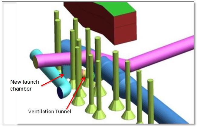
Figure 2.0 – Extract of 3D model of showing the congestion around the division tunnel The existing ventilation tunnel alignment includes two 30 degree bends, one horizontal and the second vertical. Due to the sensitivity of the surrounding structures ground movements from the tunnelling works needed to be minimised. As a consequence of this, and the physical limitations in the area, the tunnel alignment was chosen to sit directly beneath the existing ventilation tunnel as this would remain stiffer than the ground and reduce ground movements above it. As a result the new tunnel had to follow the alignment with similar 30 degree bends and pass beneath the new AP1 passenger tunnel. A plan view of the alignment can be seen in Figure 3.0 with the diversion tunnel appearing to sit within the existing tunnel.
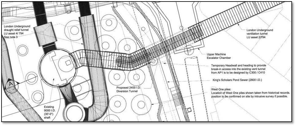
Figure 3.0 – Plan view of work site showing key assets In order to minimise disruption to London Underground, construction access for the diversion works was from the Crossrail Bond Street Station site via the new AP1 passenger tunnel. The diversion tunnel connected to the existing ventilation tunnel by means of a launch chamber at the upper end and by a tunnelled connection detail at the lower end, these connections can be seen in Figure 4.0. Headwalls were created at the connections with AP1 and the existing ventilation tunnel, and the connection between the diversion tunnel and the existing ventilation tunnel.
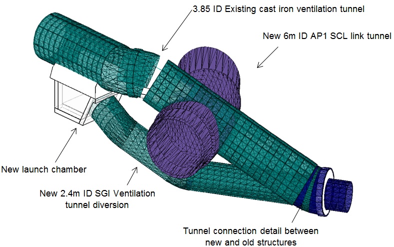
Figure 4.0 – Extract from 3D CAD model showing connection details Ground Conditions
The ground investigation indicated the proposed tunnel was to be driven into a thick seam of London clay, and this was confirmed during construction of the AP1 link tunnel. As well as known tunnelling strata, the excavated face was likely to be dry and the excavation method could be sufficiently flexible during construction if required. Whilst this provided some confidence, caution was still advisable for excavating around the many adjacent structures that had the potential to contain water and/or other localised pockets of soft ground or permeating water.
Tunnelling Method
Various tunnelling methods were considered for the works. The chosen method needed to be suitable for the access arrangements, tunnelling downhill and minimising ground movements while limiting hazards during construction. The options considered included SCL (sprayed concrete lining), SGI (spheroidal graphite iron) segments, pre-cast concrete segments, stainless steel tunnel segments and steel liner plates with a secondary concrete lining.
The tunnelling method chosen was SGI due to the various advantages outlined below.
- The thickness of the lining and its material properties was efficient as it allowed a smaller excavated profile than other methods/ materials.
- The overall method would minimise ground movements as the excavated area would be less compared to SCL.
- The tight alignment could be achieved by use of tapered segments.
- The method is relatively quick to construct onsite, notwithstanding a long lead in is required for procurement and manufacture.
- Waterproofing measures could be installed during the manufacturing process.
Other considerations were in terms of constructability. In particular, the overall design needed to allow for safe movement of the materials down the tunnel incline. It was decided during constructability meetings between Crossrail, the Contractor and the Designers to use a bogey system to allow the movement of materials; however, this required adequate space to be provided within the launch chamber from the existing ventilation tunnel. Another consideration was how close the diversion tunnel could safety be built to the AP1 tunnel. Minimising the distance between the tunnels was critical due to the constrained alignment. It also allowed the depth of the launch chamber to be reduced which minimised ground movements near piled foundations. The SCL lining was designed to accommodate the local loss of support due to the diversion tunnel construction; however, the SGI tunnel was designed to be at least 200mm below the SCL primary lining to allow a compressible material to be placed between the two tunnels. This was to eliminate any potential for point loading of the SCL lining.
Segment Design
The segments were designed to support the ground through this alignment for a 120 year design life. They also were designed to be watertight in line with the LU and Crossrail standards by using a double water proofing system.
The 2.4m internal diameter SGI ring consisted of 6 No. segments and a solid key as seen in Figure 5.0. The segments were bolted both on radial and circumferential joints, with the intention that the circle joint would be rolled. An early design consideration was whether to increase the number of segments per ring to allow for manual handling (below 25kg); however, this proved impractical in design due to the number of segments it would have required. Two sets of 3No. taper rings (each allowing a maximum 10 degree change in bearing) were required to achieve the alignment.
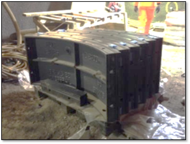
Figure 5.0 – Six segment and a key as delievered to site The design of the SGI segment geometry was driven by the manufacturing process due to the scarcity of specialist suppliers and machining availability in the UK. In particular, the material thicknesses were determined by the machinery processes the specialist suppliers used. As a result, thicknesses of the skin and ribs needed to be a minimum of 16mm.
The SGI segments were designed to incorporate the waterproofing requirements of the specification during the manufacturing process. This consisted of a machined recess to house a hydrophilic gasket detail around the segment perimeter. As a secondary means of waterproofing an internal 20mm deep caulking groove was machined in to the segment joints and accommodated a pure lead strip to be pneumatically packed into the joints on completion of the ring build. Continuity in the waterproofing detail was provided by installing oyster grummets on all bolted connections.
Launch Chamber
A launch chamber beneath the existing cast iron tunnel was required for tunnel construction. The determining factor for the chamber size was for the ring build itself and not the future maintenance access.
The opening was designed to take account of both permanent and temporary load cases. In the permanent case the hoop load from the existing lining was carried via a ring beam. This beam comprised of two curved jamb frames and two cill beams which can be seen in Figure 6.0. Along with these two curved jambs an intermediate prop was to be installed midway along the cill beams to reduce their span.
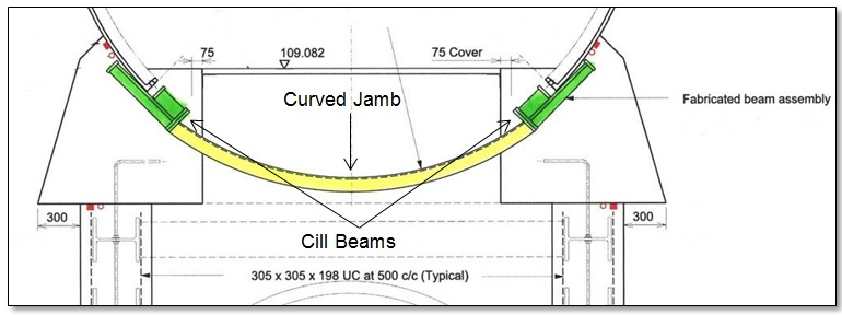
Figure 6.0 – Ring beam consisted of a curved jamb frames and cill beams In the temporary case it was possible to design out this intermediate prop by using the LU Guidance document G-055[1] which allows designs for reduced overburden in the short term during tunnelling works. This reduced the weight of the ring beam during the initial installation and allowed the contractor to maintain the maximum opening during the construction phase
The chamber beneath this opening was sized to allow for the tunnelling operations. The beams used were in fact universal columns (UCs) to reduce to the excavated volume. Soldier beams were considered; however, they were deemed to restrict the tunnel operations and were omitted.
Using Early Contractor Involvement (ECI) on the project, the design was optimised based on agreed methods of work. Therefore the frame was adjusted to suit temporary works proposals and including hanger bars to hold steelwork during construction.
Challenges to Standards
The design was required to meet both London Underground and Crossrail Standards; however, due to the alignment constraints, this was not always practical to achieve. Therefore a number of concessions were obtained from the relevant organisation.
Crossrail Concession
One concession was the omission of drainage, a requirement by Crossrail. As there is no active drainage provision in the existing ventilation tunnel there was no gravity system to connect to and any new system in the diversion would have required a sump and pump system back to the LU station which was not desired by LU as the future owners and maintainers. Given the only source of water within the diversion tunnel is groundwater ingress through the linings joints, which are designed with two methods of waterproofing to all potential water paths, and in the permanent case there would be a flow of hot air through it the tunnel, this drainage requirement was excluded from the design.
London Underground Concession
Another concession related to the maintenance stairway, both for the number of risers and a change in slope. To build a complaint stairway would have meant changing the design significantly (both tunnel size and alignment), which would generate problems with the limits of deviation for the works, planning consents from the Crossrail Act and ground movement impacts to the surrounding assets caused by the larger excavations.
As the tunnel would be accessed for maintenance only on a very infrequent basis, the health and safety risks from the non-compliant staircase, presented in Figure 7.0, were deemed as low as reasonably practical (ALARP) given the impracticality of constructing a complaint stairway.
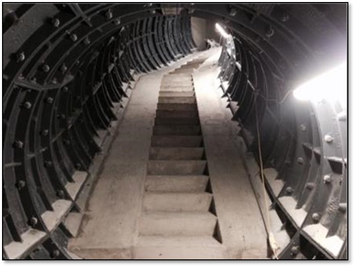
Figure 7.0 – The final staircase which was subject to an LU concession Diversion Construction
Enabling Works
Advanced enabling works were carried out by London Underground within the existing ventilation tunnel. These included asbestos removal, removal of existing M&E services and the erection of 1hr fire separation bulkheads / segregation barriers compliant with LU regulations to allow the remaining works to be carried out 24 hours a day, 7 days a week.
Access to Site
Access to the existing ventilation tunnel was achieved using a temporary heading constructed from the new Crossrail Link Passage AP1, this interface can be seen in Figure 8.0. A small section (two plates, approx. 1m x 1.5m) of existing 3.85m ID cast iron ventilation tunnel were broken through to allow for the backfilling of the existing ventilation tunnel inclined area.
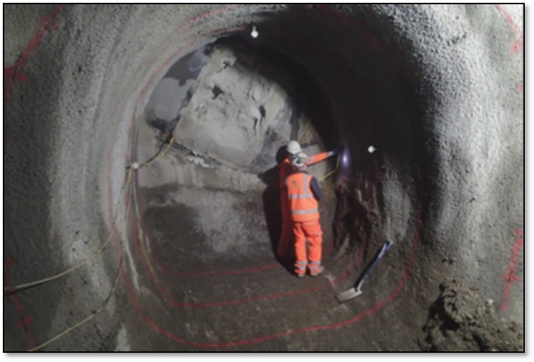
Figure 8.0 – View from within AP1 looking at the exposed ventilation tunnel Once backfilled AP1 was advanced through the foam concrete filled tunnel to the end of the SCL works and the interface with London Underground’s BSSU project. A thickening layer was sprayed around the breakout zone into the existing ventilation tunnel which can be seen in Figure 9.0.
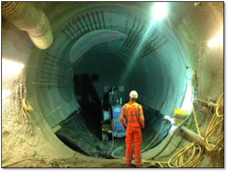
Figure 9.0 – Area of breakout from AP1 into the ventilation tunnel prior to SCL thickening Ring Beam Construction
The build of the existing cast iron tunnel comprised of 8 No. segments with no rolling of the joints. As a result the bottom two segments could be removed from 7 rings resulting in an opening of approximately 4.2m long and 2.1m wide
To create the opening in the existing tunnel required heavy temporary steel propping, as seen in Figure 10.0, to allow for the excavation and completion of the ring beam. BFK were able to shorten the initial temporary works design by using a series of short sequenced excavation and insitu concreting alongside increased frequency of asset monitoring. No significant movement of the lining was recorded and a significant reduction in the excavation programme was achieved.
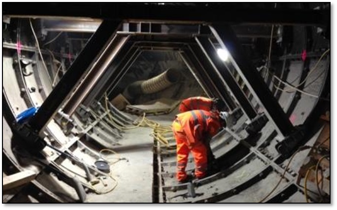
Figure 10.0 – Propping in the existing ventilation tunnel to allow removal of segments Excavation of the ring beam beneath the existing tunnel, shown in Figure 11.0, featured typical back grouted 8”x4” tantalised timbers, wedges and yankee brobs for ground support constructed using hand excavation techniques in sequenced advances.
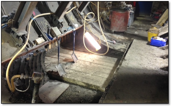
Figure 11.0 – Temporary works timbering for the ring beam beneath the existing tunnel Launch Chamber Construction
The launch chamber excavation used similar ground support, but with the additional of 6” UC temporary steel propping with a step by step sequence. This was excavated in primary and secondary excavations of 1.9m and 1.5m lifts respectively.
In the permanent case the chamber was designed to be supported using universal columns around three edges, as seen in Figure 12.0, and the first SGI ring provided the restraint at the open end. The beams were held on hanger bars from the chamber opening to allow for safe construction. Water proofing was added to the elements using hydrophilic strips and re-injectable grout tubes.
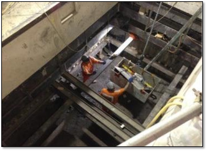
Figure 12.0 – Both permanent and temporary steelwork seen within the launch chamber Tunnel Construction
The hand excavation of the SGI tunnel itself involved the installation of 9×3 headboards across the middle two thirds of the soffit to the profile of the proceeding SGI ring. These headboards spanned forward onto battered faceboards on footblocks to an intermediate bench as can be seen in Figure 13.0.
During the excavation hard dry London clay provided excellent strata for tunnelling with an insignificant scatter of clay stones up to 250mm in diameter holding minimal water. The excavation close to the existing cast iron structures exposed good quality grouting with thickness in excess of 30mm and encountered no water paths to the excavation during construction.
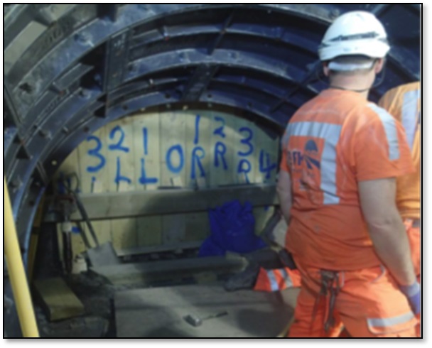
Figure 13.0 – Faceboards and footblocks at the face of the tunnel excavation Construction of the lower junction meant the excavation would have to break into the segments of the existing ventilation tunnel. Despite having removed a series of bolts before backfilling the existing tunnel, the breakout remained a significant challenge, so a track mounted pneumatic breaker, seen in Figure 14.0, was used to limit HAVS exposure.
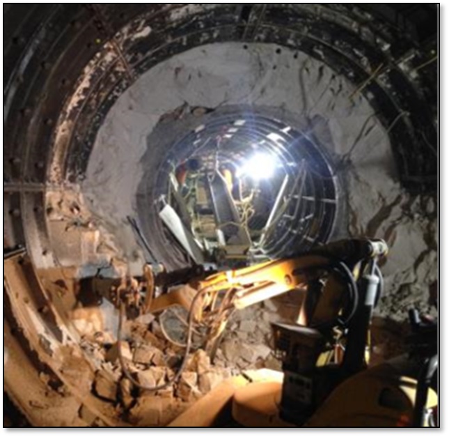
Figure 14.0 – A pneumatic breaker was used in excavation through the existing tunnel Construction Challenges
Access to the Works
Safe access and logistics throughout ventilation tunnel works presented the single most complex challenge to manage. A series of temporary structures were required to facilitate construction, including an access ramp to reach the shoulder of the AP1 tunnel which significantly reduced the height for plant operation. From here a bespoke overhead monorail gantry was fabricated in the existing tunnel allowing for efficient lifting operations. This monorail serviced the launch chamber area which fed a series of air winches and a bogey system, as seen in Figure 15.0.
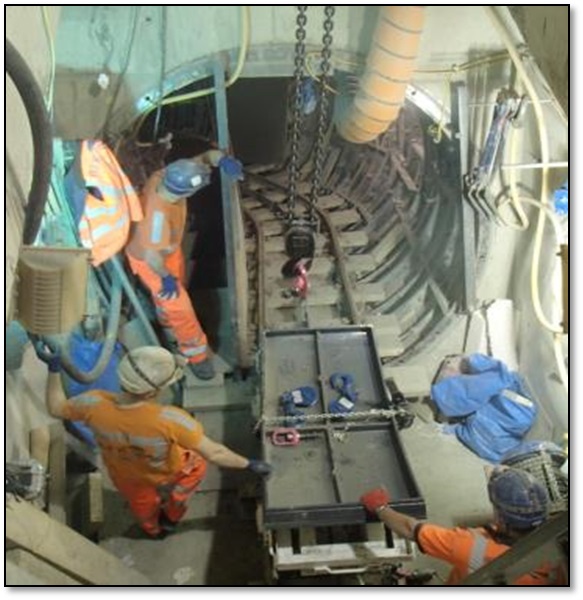
Figure 15.0 – Workers awaiting clearance to operate the bogey Due to the significant hazards involved in its operation the inclusion of the bogey and rail system was only undertaken once all other available options had been ruled out as impractical. In comparison to conveyors and other methods the introduction of bogey and rails increased the risk of a life changing injury or fatality. A detailed risk assessment approach was undertaken to install a system that provided both a practical and safe solution to cater for muck away, segment movement and maintain safe access arrangements for the workforce. The bogey was connected to two independent air winches, a free fall failsafe rack and an advancing stopblock that was extended forward as works progressed. This risk was mitigated further by installing a bespoke raised pedestrian walkway to separate pedestrians from the bogey in the inclined area. Site communication was further improved by an innovation from the workforce who customised a reversing camera from an excavator to provide a screen for the winch operator to clearly monitor the bottom of the incline area before operating the air winches. The operatives involved were commended for improving the safety features of the section.
The provision of emergency access and egress was paramount to maintaining a safe work area during construction. Egress routes through LU back of house and machine chamber areas was provided as a secondary means of escape in the event of the AP1 exit becoming unsafe in an emergency. BFK enacted a mock stretcher evacuation from the SGI excavation works with each shift to ensure familiarity with procedures.
Tunnel Alignment
Following the completion of the first two taper rings in the tunnel’s construction (the 4th and 5th rings into the tunnel drive) it was discovered the alignment was diverging from design. Due to the short length of the tunnel it was not deemed possible to bring the alignment back to design solely using the adjustability present between the remaining rings. A number of alternative solutions were explored to solve the issue which included;
- Construction of the third taper with a ‘birdsmouth’ and a lead packing detail
- Removal of the two existing tapers and rebuilding of the first as an independent ring with the key in a different (and non-standard) position
- Removal of all the constructed rings and rebuilding with the key in a different position from the start.
Rebuilding the two tapered rings with the key in a different position was viewed as the most effective and practicable solution. In the permanent case ring to ring bolts were not required for structural stability. The independent ring was constructed with the aid of clamps and props in the absence of bolted connections to the previous ring. The end result meant the tunnel was constructed as per the design alignment.
Passing under AP1
On review of the excavation profiles for AP1 it was noted that its primary lining had been over excavated in the area above the ventilation tunnel. As a result there was insufficient clearance to the SCL lining for installation of the compressible fill. A number of cores were taken into the SCL lining to confirm the as-built SCL thickness. These cores demonstrated that the primary lining had been over-sprayed and could be broken back to provide the required clearance without reducing the minimum structural thickness.
Corrosion Protection Coating
The SGI rings were specified to be coated with a three layer system in accordance with the LU specification T0005[2] for Bridges and Highways as referenced for in the LU specification T0006[3] for Deep Tubes Tunnels. These coatings were also to be compliant with the LU fire safety standard LU 1-085[4]. During the close out of the project it was discovered the coatings applied, though compliant with T0005, did not have the required test results to demonstrate that the products meet LU 1-085 standard. Tests for this standard involves a 3-4 week lead time and requires large numbers of product samples, applied to SGI, varying in size up to 1.2m x 0.3m. Due to time constraints on projects completion it was agreed between all interested parties the quickest and most certain way to resolve the issue of compliance was to grit blast the existing coating off and recoat with a two part epoxy coating which satisfied LU.
Lessons Learnt
Early Contractor Involvement
The use of ECI allowed for effective project planning and the maximum level of risk reduction possible. Another significant benefit was the fact it allowed for the permanent works design to take account of temporary works requirements and for adjustments to be made in order to maximise the limited space available on-site. It also allowed for the optimisation of the design by looking at the size of elements, such as the cill beams, with respect to the construction sequence and programme.
SGI Segment Design
The availability of specialist suppliers proved to be the driving factor in the design of the SGI segments. Given the limited geometries which could be machined in the UK it proved advantageous both from a programme and cost point of view to bring the supplier on board early in the design process.
Temporary Works
By working with the temporary works designer and optimising the excavation sequence the ring beam construction yielded significant programme benefits. A good working relationship with the design teams, favourable ground conditions, increased monitoring frequencies and the provision of contingency measures on hand were key to delivering an assured approach.
In principle avoiding a rail and bogey system wherever possible should be promoted to reduce hazard exposure to the workforce and reliance on lifting operations; however, if unavoidable the system can be successfully managed with a series of safety considerations, thorough and regular supervision and an experienced workforce. Advancing air winches forward as works progress for building SGI segments reduces loading on lifting points, reduced open tensioned cable length and improved visibility of the lifting operation.
Conclusion
The project was successfully completed overcoming a number of complex engineering and construction challenges. It was done so without any lost time incidents recorded and has demonstrated that traditional handworks can still have a role to play in modern tunnelling projects. Well managed interfaces, early contractor involvement and an effective project delivery team all proved to be key in achieving the success.
References
[1] London Underground Manual of Good Practice G-055: Civil Engineering – Deep Tube.
[2] Tunnels and Shafts London Underground Standard: 1-085 Fire Safety Performance of Materials.
[3] London Underground Technical Specification: T0005 Bridges and Structures Materials and Workmanship .
[4] London Underground Technical Specification: T0006 Deep Tube Tunnels Materials and Workmanship.
-
Authors