Design and Construction of Inclined Escalator Shafts and Stair Adit at Liverpool St and Whitechapel Stations
Document
type: Technical Paper
Author:
Eleanor Sillerico Mayta MSc, Jose Suarez Diaz MSc CEng MICE, Romain Vivier Ing(Fr), Eric Marchand, Sam Ahmad MSc BEng CEng MICE, ICE Publishing
Publication
Date: 09/07/2018
-
Read the full document
Notation
CRL Crossrail
SCL Sprayed Concrete Lining
SFR Steel fibre reinforced
BBMV Balfour Beatty, BeMo, Morgan Sindall, Vinci
NESRS North Eastern Storm Relief Sewer tunnel
LU London Underground
NR Network Rail
WAGN West Anglia and Great Northern
NLL Northern Line Link
SOP Setting out point
RILEM International Union of Laboratories and Experts in Construction Materials, Systems and Structures
FEM Finite Element Model
CEDS Civil Engineering Design Standards
ES Escalator Shaft
Introduction
Crossrail Contract C510’s scope of works covers the Liverpool St and Whitechapel Stations sprayed concrete lining (SCL) structures which include primary lining, waterproofing system and secondary lining including fireproofing protection. Within these structures are the escalator inclined shafts and inclined adit. Crossrail awarded contract C121 (Design) to Mott MacDonald Ltd. and C510 (Construction) to Balfour Beatty, BeMo, Morgan Sindall, Vinci BBMV Joint Venture.
This paper will briefly describe the two escalator shafts and the adit at Liverpool St Station and one escalator shaft at Whitechapel Station; followed by a detailed description of the design and construction of ES3 (as ES1 and ES2 are reasonably similar) and AP10b.
Whitechapel Station
The main and only entrance to Whitechapel Station will be through the new ticket hall providing access from the Durward Street Shaft to the platform tunnels through Escalator ES1, see Figure 1.

Figure 1. Whitechapel Station 3D Model showing Escalator ES1
ES1 is 19 m below ground level, has an inclination of 30° and is situated 1.4 m beneath the existing NESRS (see figure 2).
Figure 2. ES1: Long section (left) and plan view (right)
Liverpool St Station
Liverpool Street Station (42 m below ground level) is the deepest station on the Crossrail Project with two new passenger ticket halls linked via the concourse tunnel (AP7), cross passages and two escalators ES2 and ES3 to the lower CRL platform tunnels providing an interchange with LU Metropolitan and Circle Lines and Network Rail (NR) Services. In addition, the Northern Line Link (NLL) will be provided to interchange with the existing LU Northern Line at Moorgate Station through the construction of an inclined adit AP10b (Figure 3).
Figure 3. Liverpool St Station 3D Model showing the location of Escalator Shafts ES2, ES3 and inclined adit AP10b
Escalator ES2 is located 30 m below ground level, has an inclination of 30°, it is skewed in plan and located only 6 m below “the London Wall Buildings” foundations. See Figure 4.
Figure 4. ES2 Long section and plan view (bottom left)
Due to access issues from Moorgate Shaft the excavation was forced to be uphill. The excavation of ES1, ES2 and ES3 was carried out using an uphill excavator and spraying machine known as the GTA Uphill excavator (www.gta.eu) which is a combined excavation/spraying moving bucket hanging from the tunnel crown. In order to allow the excavator to hang from the crown the primary lining thickness had to be locally increased from 300mm to 800mm in the crown all along the incline as shown in Figure 6.
Escalator ES3 is located 26 m below ground level, has an inclination of 30° and only 8 m below the “Electra and Salisbury House” foundations; and 3m below the river terrace deposits which precisely lead to the installation of 3 groups of pipe arches to prevent any undesired settlements during ES3 excavation.
Figure 5. ES3 Long section and plan view
Figure 6. ES3 Cross Sections: section A (left) and F (right)
AP10b: The connection between the Crossrail station and the existing LU Northern Line is known as the Northern Line Link NLL (see Figure 7).
Figure 7. AP10b long section
AP10b is the only inclined pedestrian adit at Liverpool St Station AND WAS built using SCL for both primary and secondary lining with sprayed waterproofing system. The bottom is located 29m below ground level and is right beneath and parallel to an existing LU Escalator (that links the LU Northern Line with the NR WAGN platforms). AP10b and the LU escalator are separated by less than 500mm from each other representing a serious constraint during the excavation. Additionally, the excavation of AP10b clashed with the existing concrete wall and sump.


Figure 8. AP10b cross sections: section H (left) and G (right)
Table 1: Summary of geometry properties of ES1, ES2, ES3 and AP10b
Tunnel Material Extrados width (mm) Extrados height (mm) Lining thickness (mm) ES1, ES2 & ES3 pilot tunnel SFR SCL 6080 6150 500 (crown) / 325 (sides and invert) ES1 & ES2 Primary lining enlargement SFR SCL 9000 7915 300 ES3 Primary lining enlargement SFR SCL 9000 8077 (sec A) 300 8698 (sec F) AP10b Primary lining SFR SCL 5240 (variable) 6910 (variable) 275 ES1 Secondary lining SCL above axis level 8200 7115 250 (crown) Cast in-situ invert and sides 600 (invert) / 250 (sides) ES2 Secondary lining Cast in-situ except for the upper curve 8200 7115 250 (crown) 600 (invert) / 250 (sides) ES3 Secondary lining Cast in-situ 8200 7150 (sec A) 250 (crown) / 600 (invert) / 250 (sides) 7900 (sec F) 1000 (crown) / 650 (invert) / 250 (sides) AP10b Secondary lining SCL 4400 (variable) 4350 (variable) 225 min (variable) Design Considerations
Primary Lining Design (Ground Support)
The primary lining design of ES1, ES2, ES3 and AP10b were carried out by BeMO and category III checked by Mott Mac Donald Ltd.
To analyse the SCL primary lining of ES1, ES2, ES3 and AP10b; a numerical modelling programme FLAC 2D has been used to develop a 2D plane strain model that allows assessing the interaction between soil and structure considering both elastic and plastic behaviour when needed.
Although, FLAC models SCL as a linear elastic material leading at some cases to get high tensile and flexure stresses; a plastic approach can be introduced in the model redistributing the bending moments through plastic rotations. Once modelling is complete, then the structural capacity of the SFR SCL is checked in line with RILEM[2] and Eurocode 2[1] (although currently EC2 does not contain a section for SCL design, C121 developed a design methodology). The analysis also takes into account the age variation of the material properties, i.e. young modulus, compressive strength, creep and shrinkage of sprayed concrete.
Since the design and construction approaches for ES1, ES2 and ES3 are similar only ES3 will be described in this paper.
Escalators ES3
Figure 9 shows the geological context at Liverpool St Station and locates ES2 and ES3 within London Clay. ES3 upper chamber is in near proximity to the River Terrace Deposits which lead to the installation of three pipe arches on AP9 (see Figure 5) and precisely one of them was installed right above ES3 to avoid undesired movements on buildings due to ES3 excavation but also to increase the safety during the construction of the primary lining.

Figure 9. Geological profile at Liverpool St Station and ES2 & ES3 location
ES3 excavation sequence (Figure 10 and Figure 11):
- Uphill excavation of the pilot tunnel done by 1 m advances.
- Downhill excavation of the top heading enlargement done by 1 m advance leaving the temporary invert in place.
- Downhill excavation of the invert enlargement and removal of temporary invert done by 2m advances.
The design assumption was maximum advance rate for the enlargement 20 m / 5 days with a maximum peak rate of 6m / day which was included in the FLAC model.
Two locations were studied: at the bottom and at the top; analysing 3 different sections per location: pilot tunnel, top heading enlargement and final section.
- Bottom section: CH5 located beneath ES3 invert creates a stiffer area (Figure 10) causing an increase in bending moments and shear stresses especially at the corners of the temporary invert.
- Top section: The impact of the junction between CH5 and CP2 which is right below ES3 invert has been assessed.
Figure 10. ES3 excavation sequence
Figure 11. ES3 Excavation sections A (left: bottom) and B (right: top)
The numerical modelling results and the structural capacity check showed the 300mm primary lining for ES3 was within capacity up to short term stage or un-drained condition of London Clay (Figure 12). In the long term cases where the drained soil properties and groundwater pressures were fully applied the primary lining capacity was slightly out of capacity particularly at the corners of the temporary invert when it was removed to install the final permanent invert. The easy solution would have been to install additional reinforcement in the primary lining impacting the construction programme but at the same time increasing the risk of leaving open excavated sections due to steel bar reinforcement installation works. Therefore, a combined solution was agreed between the designer and contractor: a part of the primary lining long term loads were transferred onto the secondary lining which had to be installed within 9 month after primary lining completion.
Figure 12. ES3 primary lining bending moments on un-drained soil condition (short term)
AP10b Inclined adit
From all 4 inclined tunnels at LIS and WHI, AP10b represented the most challenging in terms of impact on existing LU infrastructure; in particular: LU escalator right above AP10b (see Figure 7) running parallel to AP10b. Figure 13 shows a cross section of all structures involved during the primary lining design. All LU structures were still running while AP10b was excavated; hence why the displacements generated on them as a result of AP10b excavation had to be carefully and continuously monitored.
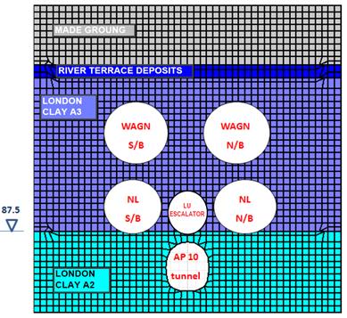
Figure 13. Geological profile at the NLL and AP10b surrounded by existing structures
The AP10 excavation sequence was set up metre by metre and performed uphill by means of sloping full face advances all along the adit using the excavation system known as LasershellTM proposed by the contractor. The maximum excavation advances rates were: from advances 1 to 12: 2m/day and from advances 13 onwards: 1m/day which were considered in the FLAC model.
The cross-sectional geometry of AP10b is changing throughout its full length (Figure 14). Three representative sections (Figure 15) were considered in the design in terms of the structural behaviour in the temporary case during excavation and primary lining installation.
Figure 14. AP10b excavation sequence
Figure 15. AP10b cross sections D1, D3 and D4
The numerical modelling showed the following findings:
- Section D1: 275mm SFR concrete lining is within capacity in the elastic analysis in short and long term stages.
- Section D3:
- 275mm SFR concrete lining fails in the elastic analysis both in short and long term stage.
- Plastic analysis was required introducing plastic hinges in the lining (Figure 16). The bending moments and shear forces have been checked limiting the crack width and rotation at the location of the hinges and found the SFR concrete lining was within capacity.
- Section D4:
- 275mm SFR concrete lining fails in the bending moment/axial force capacity check in the elastic analysis both in short and long term stage.
- Plastic analysis was required as per in section D3 and the lining was found within capacity at the end of the analysis.
Figure 16. Location of plastic hinges in sections D3 and D4
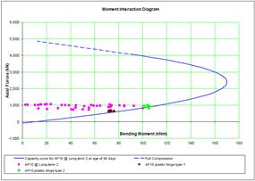
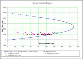
Figure 17. Bending moment – axial force capacity check for section D3 and D4
Secondary Lining (Permanent Lining)
A numerical modelling in a finite element (FE) software “STAAD” has been used for ES3 and AP10b.
ES3
Geometry: ES3 section has variable thickness from bottom to top, with 250 mm of thickness at sides, a variable thickness from 250 mm up to 600 mm at invert and being the crown backfill transferred into the secondary lining creating a variable geometry all along the escalator crown (Figure 5).
Due to variable geometry a FEM 3D model has been developed to analyse the structural behaviour of ES3 and determine the required reinforcement (Figure 18).
Figure 18: ES3 FEM 3D model. Longitudinal half-section
The boundary conditions are influenced by the presence of foam concrete backfill at the bottom of the escalator and transition tunnel (see Figure 10). This block of concrete induces a differential structural behaviour between bottom and upper sections since the ground stiffness confining the tunnels is varying causing an increase of the reinforcement in longitudinal and hoop direction to guaranteed the serviceability (crack width < 0.3 mm[1]):
Material properties: ES3 tunnel has been designed with a grade C32/40 cast in situ SFR concrete. The construction sequence considered in the design is: cast the invert, and then, with the help of a movable shutter, sides and crown. The potential risk of cracking due to the early age thermal crack and long term drying shrinkage has been analysed as per CIRIA 660[3]. This assessment determined to add longitudinal bars B12@100 in both faces above the construction joint invert/wings.
Loading / load combinations: ES3 secondary lining has been designed to carry the full earth pressure since the structural competence of the primary lining in long term condition was compromised according to the numerical analysis carried out previously and full pore water pressure.
The biggest tensile stresses in hoop and longitudinal directions (yellow and red colours contours) are concentrated on near/top face of inverts along ES3 barrel, and on far faces of side walls below axis level. The vault is generally in compression although there are areas with small tensile stress (orange contours) on near face of the crown in the vicinity of contraction joints as a consequence of the model boundaries conditions (Figure 19).
Figure 19: Stress contours on near (left) and far face (right) in escalator barrel.
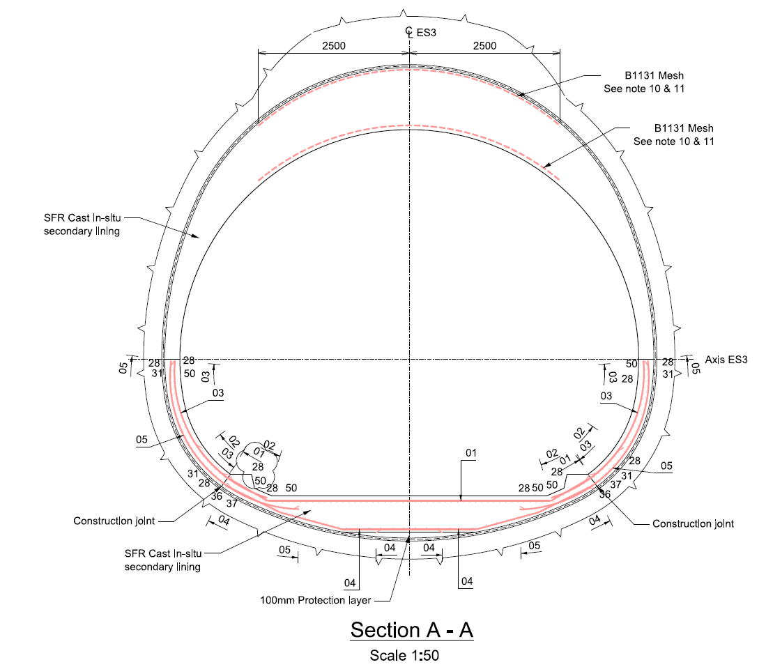
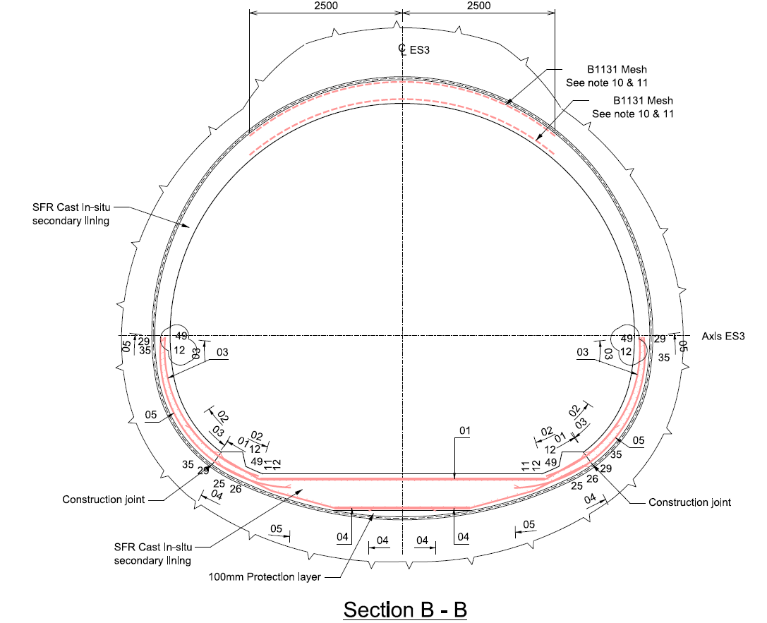
Structural design and reinforcement detailing. According to the numerical modelling results and the structural requirements as per EC2[1], ES3 crown reinforcement required a B1131 mesh to control cracking due to the early age thermal crack effect in accordance to CIRIA 660[3].
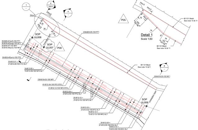
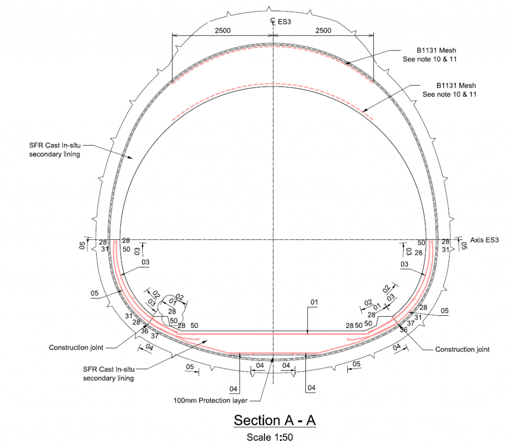

Figure 20: ES3 Reinforcement details set up as per BS 8666 [4]. Long and cross sections
The main reinforcement at the invert top face and side walls far face are B25@100 which provides enough capacity to withstand the pore water pressure in long term conditions. B12s@100 are provided in longitudinal direction to control the crack width due to early age thermal crack effect.
AP10b
AP10b tunnel has a very complex geometry with 16 different cross sections all along it (Figure 21):

Figure 21: Analysed Sections of AP10b
Some AP10b particularities are:
- Between primary and secondary lining there is an infill of mass concrete to follow the profile of this tunnel at the invert level.
- Secondary lining thickness is varying along the tunnel as is detailed in Table 2.
Table 2: Summary of AP10b secondary lining variable thickness
Tunnel
Section
Axis level Ground level to tunnel axis Crown Tunnel Axis Invert (mATD) (m) (mm) (mm) (mm) D1 82.911 31.089 225 225 225 D3 83.903 30.097 225 270 350 D4 86.884 27.116 225 300 350 D5 87.232 26.768 225 300 350 D7 90.396 23.604 225 225 225 Five representative sections were selected to evaluate AP10b structural behaviour (Figure 21). The variable geometry is a determining challenge of this tunnel design.
Two types of C32/40 concrete mixes have been considered in the design; SFR sprayed concrete lining (where no steel bars were needed) and sprayed plain concrete (where steel bars were needed) to prevent encapsulation.
Loading / load combinations:
- Earth pressure varies with the depth and different load sharing between primary and secondary linings in long term conditions as per the outputs of the numerical analysis in FLAC.
- Pore Water Pressure varies with depth and hence is different for each analysed section.
- The proximity of existing tunnels impacts on AP10b structural behaviour and how ground loads are acting on both linings, primary and secondary.
Five separate 2D numerical models have been studied where different loading conditions are considered. In doing so, a complex and time consuming 3D model was discarded. An example of deformed shape and bending moments are shown in Figure 22:
Figure 22: Deformed shape and bending moments for Section D5-D5
Reinforcement detailing: to detail reinforcement in SCL is essential to avoid encapsulation issues such the following need to be considered:
- Maximum bar diameter. For AP10b B16s bars with plain concrete did not present encapsulation issues.
- Minimum bar spacing. For AP10b a 150 mm spacing with plain concrete did not present encapsulation issues.
- Anchorages lengths of rebar have been prioritized over lapping lengths.
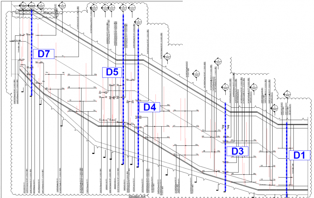
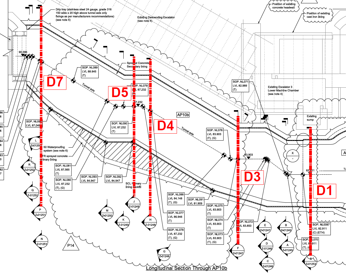
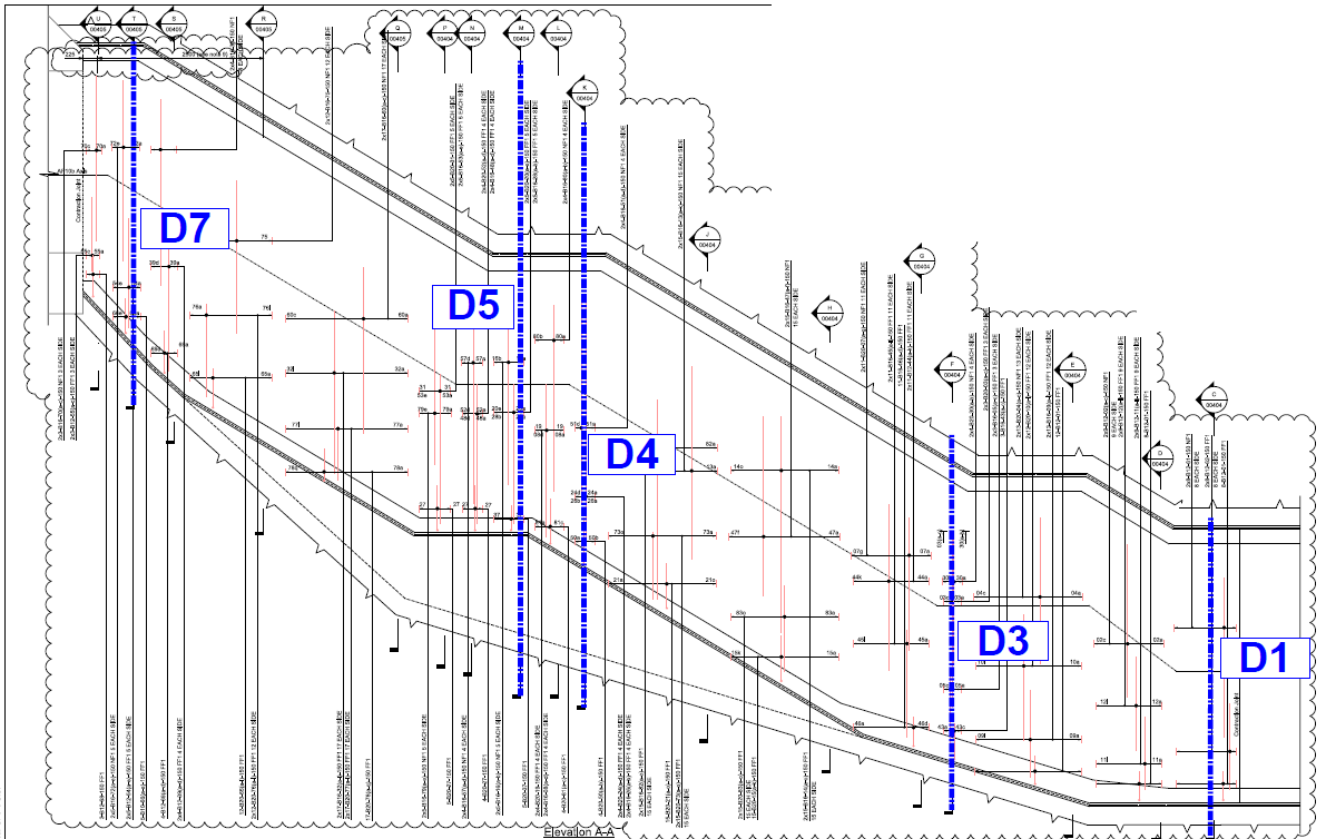
Figure 23. AP10b reinforcement. Long Section
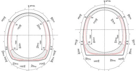
Figure 24: Reinforcement in transition between sections D4-D4 and D5-D5
Above figures show areas where SFRC is sprayed (dashed contours) and areas where plain concrete is sprayed in combination with conventional reinforcement (solid) to ensure the structural competence and serviceability of the tunnel.
Construction Process
ES3:
The main safety challenge for the uphill excavation was to avoid people and equipment to be based on the invert of the inclined shaft, while we carry out its excavation and to eliminate the risk of being hit by muck. It became clear that people and equipment had to be located above the tunnel axis, close to the vault. In partnership with the specialist German plant supplier GTA, a prototype of uphill tunnel excavator was developed.
To allow GTA Uphill excavator to be hung from the crown we had to assemble a steel frame made of an overhead suspension casted into SCL or post drilled supporting chains. Chains support suspended rails and sleepers. To brace the whole system, side chain and turnbuckles were fixed to horizontal anchors.

Figure 25. GTA Uphill excavator suspension arrangement
Pilot tunnel was a 25 m2 section out of 71m2 from the enlarged section. The purpose to sequence the final excavation is to reduce the surface settlements. We observed an average value of 12mm with compensation grouting and 15mm for the enlarged section.
Reinforcement was installed in the pilot tunnel from the basket mounted onto the GTA boom which was highly time consuming.
To move the machine forward sub-carriers were installed at crown. These carriers were sprayed in and to avoid any voids re-injectable hoses were looped that subsequently were back grouted before commencing the enlargement works.
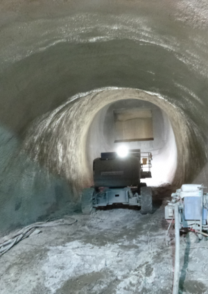
Figure 26. GTA Uphill excavator
In terms of production of the pilot tunnel, the installation and suspension of the GTA from the tunnels crown was intricate and time consuming due to fixings and preparation
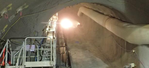
Figure 27. ES3 pilot tunnel completed
The enlargement works have been done in two different phases: top heading and invert. The volume of ground opened has been reduced to limit surface settlement. Excavations have been carried out from top to bottom. It is important to note that two sequences of enlargement were used both at Whitechapel and Liverpool Street Station. At Whitechapel we excavated two top heading followed with one double invert. At Liverpool Street the invert phase did not start before the top heading was finished.

Figure 28. ES3 top heading enlargement (works ongoing)
Figure 29. ES3 invert enlargement (works ongoing)
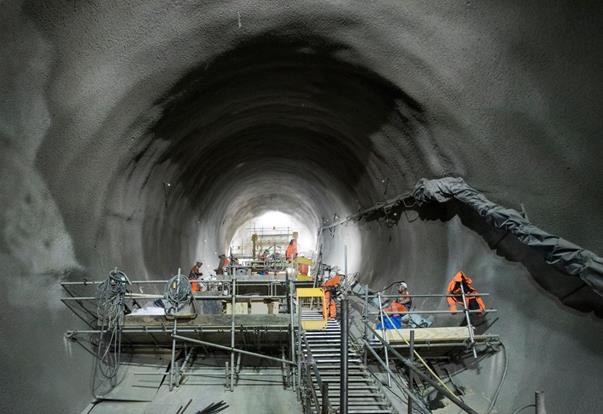
Figure 30. ES3 Primary lining completed
Outputs showed no difference between both sequences although it was found more comfortable to bring all services with us once. The crown of the pilot tunnel has been kept and incorporated into the enlarged crown section.
Breaking out the temporary invert was very time consuming and modified the work programme given the restricted breaking time and noise limits.
A PVC sheet membrane was installed in ES3 and associated water bars and re-injectable hoses at joints. The waterproofing membrane was installed into two phases. First from the invert and using a rope access system, operatives installed membrane as high as it was safe to go. Then, after all inverts were poured; a scaffold wad assembled to connect the waterproofing to the crown.

Figure 31. Sheet waterproofing membrane fully installed in ES3
To cast the invert, a metallic shutter was used that was anchored with two systems. First, 5 spiral dowels installed into each pour. These dowels provided an anchor for the rear of the shutter. Secondly, specific to the invert shutter, a row of dywidag threaded bars were installed and connected to BA anchors chemically fixed into primary lining and welded to sheet membrane. As a collective protection a levelled platform was fixed to eliminate the risk of working on a slope. It was decided to install couplers into the near face reinforcement to eliminate any reinforcement protruding in the leading edge. The installation of steel into wings and crown was completed from the scaffolding platform designed to install the waterproofing membrane.
It is important to note that installing reinforcement onto a sprayed concrete lining gives different back-cover due to the irregularity of the lining. Also the thickness of the crown between primary and secondary lining varied from 400mm to 1200mm.
A KERN shutter was used for the vault. It was set onto rails and had front and back legs to push forward and climb up-slope. It had working platform for both leading and trailing edge to ease the installation of stop-end and up-lift pads.
The full thickness of secondary lining contained polypropylene fibres at 2kg/m3 for fire protection. All concrete pours were successful. The pump rate was limited not to exceed the maximum rate of pours and waited for an increase of temperature of concrete before to load the shutter above axis.
Tunnelling with GTA was safe and major issues were not faced. The overall system needs to be more performing and more durable. There is an excellent feedback on Crossrail C510 that will help creating a beta version of uphill excavator. The cast in situ secondary lining was the only solution available considering the use of sheet membrane at crown and given the density of reinforcement installed.
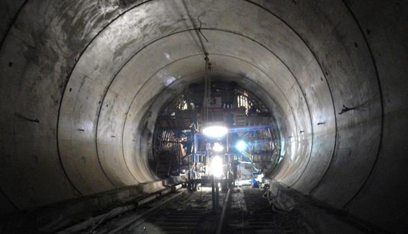
Figure 32. ES3 secondary lining completed
AP10b:
All materials were supplied through Moorgate Shaft. Every lifting landed onto AP6 timber platform and was sent to AP10b. On AP6 deck a concrete boom was installed to regulate and control the concrete supply. All concrete deliveries were supplied from Finsbury Circus Shaft and sent throughout the tunnels. Mucking out was organized with track dumpers and taken away with the crawler crane. AP10a was constructed before AP10b to gain enough space during the completion of excavation and primary lining installation.
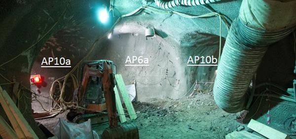
Figure 33. The NLL: AP10a, AP6a and AP10b primary lining
AP10b was excavated using a Kaiser walking excavator. The walking excavator’s main feature is the ability to move in a crab or spider-like fashion and hence overcome the gradient of the tunnel. It is electrically supplied and got large flotation tyres to maximize adherence. It was a determining factor to use a precise excavator with a big supply of power and boom movements to achieve the variable geometry along the tunnel.
To support all exposed faces we used a Meyco POTENZA as a spraying unit. It had to be replaced after the first half of the tunnel was finished as the gradient was too steep. We used a Pulzmeister Wetkret which is designed for small tunnel sections with difficult access. It is mounted on a compact crawler chassis and support legs. It also features a +/-30º tilting system, guaranteeing stable operation in ascending and descending slopes.

Figure 34. Excavation Sequence: Top heading + triple invert and full face excavation
The face was broke-out using Brokk400 and excavated 3 top headings + inverts. The exiting LU sump was exposed at crown and installed fibreboards between our shotcrete and this sump. The spraying activity had to be very precise to target the minimum design thickness without encroaching the outline profile. Then full profile was excavated. Although the steep gradient represented a very complicated constraint, the excavation was successful.
Furthermore there have been no noise, dust or vibration complaints from station staff or the public given the construction took place night and day.
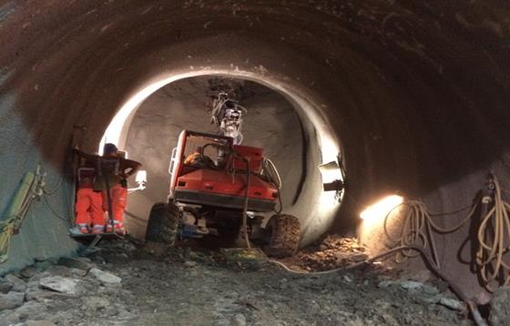
Figure 35. AP10b excavation and primary lining installation
A sprayed applied waterproofing system was used: BASF Masterseal. Previously, a 40mm regulating layer was applied on the primary lining to smooth-out the surface and cover the steel fibres contained in the primary lining mix. The main constraint of this product is the curing time which can take more than 24 hours per 3mm layer.
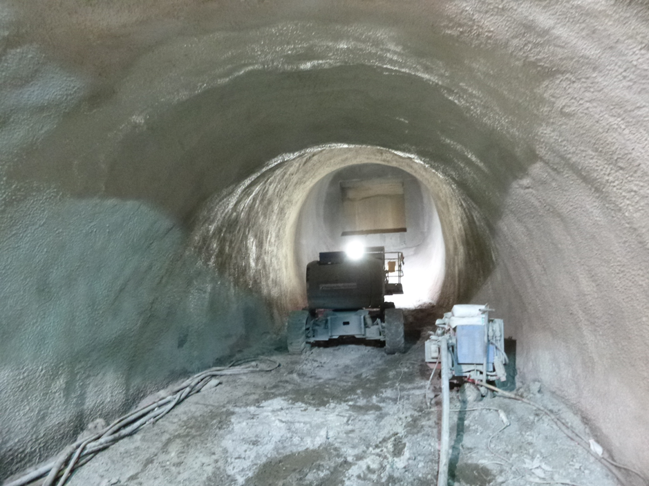
Figure 36. AP10 waterproofing layer installation
The secondary lining reinforcement of AP10b was composed of two layers: far face and near face.
- Installation of the far face reinforcement with a non-steel fibre mix first layer.
- Installation of the near face reinforcement and stainless steel profile bars sprayed with non-steel fibre mix with polypropylene fibres added at 2kg/m3 for fire protection.
The installation of reinforcement was extremely difficult as the reinforcement details were changing along the tunnel and the supply was coming through invert where the waterproofing membrane was already applied. Also working on slope and trying to protect the already installed waterproofing membrane was extremely challenging.
The construction time to complete both primary and secondary lining took a month and a half. From the construction point of view AP10b was a success in terms of safety as no incidents or accident were reported and in terms of quality: rebar encapsulation was reported.
Innovations
- Currently EC2 does not contain a dedicated section for SCL design; therefore, Mott MacDonald developed a tailored design methodology integrating diverse codes of practice such as Eurocode 2, RILEM TC 162 and CIRIA 660 for both structural capacity check (Ultimate Limit State ULS) and crack control (Service Limit State SLS).
- The GTA uphill excavator can in principle be used for any inclined tunnel excavation in certain type of ground conditions. It enables major projects with several interfaces with other contracts to bring independency in terms of planning.
- Use of sloping excavated face in construction of tunnels rather than top heading and invert. The innovative system is known as LasershellTM developed by BeMO.
Lessons learnt
- Although the use of 3D FE models is time consuming it is the best option to accurately model the tunnel longitudinal behaviour, geometry complexity and variable boundary conditions. Furthermore, using 3D FE models enables to a more realistic structural behaviour of the tunnel allowing the refinement of reinforcement.
- Incorporation of poly propylene fibres into the SFR concrete mix for fire protection successfully achieved.
- Detailing of reinforcement in SCL. High concentration of reinforcement can lead to encapsulation issues; therefore, depending on method of spraying: machine or hand spraying, certain limitations need to be considered i.e. maximum bar diameter, minimum bar spacing, number of layers and bending in bars (as per British standard BS8666).
- Tolerances: Contractor BBMV identified the need of 100mm construction tolerance to prevent encroachment into the allowed space-proofing and to reduce to the minimum the milling back operation. Also, BBMV used stain steel profile bars to mark the inner face of primary and secondary lining layer.at Liverpool St and Whitechapel Stations in order to reduce the risk of encroachment into the allowed space-proofing.
Conclusions
- All ES1, ES2, ES3 and AP10b were successfully designed and build in terms of safety and quality thanks to a jointly cooperation between CRL, Contractor and Designer.
- The SCL permanent lining was much more appropriate for AP10b given the complex and variable geometry of the inclined adit.
- The cast in-situ permanent lining in ES3 allowed building the variable thickness at crown successfully as the SCL methodology would have been inappropriate in this case in terms of programme.
References
[1] Eurocode 2. BS EN 1992-1-1 Design of concrete structures. Part 1.1: General rules.
[2] RILEM TC 162-TDF: ‘Test and design methods for steel fibre reinforced concrete’.
[3] CIRIA C660: Early-age thermal crack control in concrete.
[4] BS 8666:2005: Scheduling, dimensioning, bending and cutting of steel reinforcement for concrete – Specification.
-
Authors

Eleanor Sillerico Mayta MSc - Mott MacDonald
C121 Tunnel Design Lead
Jose Suarez Diaz MSc CEng MICE - Mott MacDonald
C121 Design Manager
Romain Vivier Ing(Fr)
Construction Co-ordinator, C510
Sam Ahmad MSc BEng CEng MICE - Crossrail Ltd
Field Engineer