Design of Paddington Station
Document
type: Technical Paper
Author:
Richard Scantlebury MEng MA(Cantab) CEng MICE, Gerard Brennan BE MSc DIC CEng MIStructE, Mark Raiss MA MSc DIC PhD CEng FICE FIStructE FCS, ICE Publishing
Publication
Date: 03/11/2014
-
Read the full document
Introduction
Located to the South-West of the existing mainline station, underneath Eastbourne Terrace and Departures Road, the Crossrail station at Paddington will connect this new railway with an already bustling transport hub. Paddington connects four London Underground (LU) lines and a myriad of bus routes with trains to Heathrow and national mainline destinations. The existing infrastructure is rich in engineering and architectural heritage: Brunel’s mainline station opened in 1854 and was shortly followed in 1863 by the western terminus of the Metropolitan Railway, the first underground railway in the world.
Building a new underground station for Crossrail in this location therefore presents significant challenges and opportunities both for design and construction. The final design has been driven by efficiency, buildability, physical constraints, functionality and the need to provide a station appropriate to this location and historical setting. This discussion considers in turn the constraints which drive so much of the final outcome, an overview of how the design has developed, and a description of the final structure both in terms of design and construction.
Constraints
Existing buildings and infrastructure
As with so many of the Crossrail stations in central London, existing structures provide stringent physical constraints which dictate limits for the new construction. Figures 1 and 2 show the location and surrounding buildings, which are described below:
• Mainline station to the north-east of the site, dates to 1854 and is Grade I listed. Originally the taxi rank servicing the station was located along Departures Road, however this has been relocated to the north of the station by an earlier phase of the project.
• The canopy above the taxi rank in Departures Road is listed by association, although it has been modified many times and is now deemed to have little historical value.
• London Underground (LU) stations for the Bakerloo line to the north-east of the mainline station, and District and Circle lines at the south-eastern end of Eastbourne Terrace.
• ‘Macmillan House’ between Departures Road and the mainline station. These terraced structures, owned by Network Rail, run alongside the original taxi-rank. Macmillan House includes the ‘bomb-gap’ area, a 50 m long portion of the structure which was destroyed during World War II and replaced with a low-rise office block.
• Modern office blocks to the south-west of the site, with thresholds at the Eastbourne Terrace street level some 3.5 m above Departures Road.
• ‘Sub-station N’, located below Macmillan House and providing power for the mainline station and other Network Rail assets.
• Hilton Hotel located at the eastern end of Departures Road.
• A capped brick sewer beneath Eastbourne Terrace, removed as part of the Crossrail works.
• The ‘Osborne Tunnel’ beneath the road at the western end of the site, used for servicing on-board catering for mainline trains.
• A utility corridor beneath the Eastbourne Terrace footpath, into which numerous services have been diverted by a prior contract.
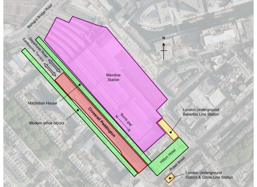
Figure: 1 – Location plan including existing buildings
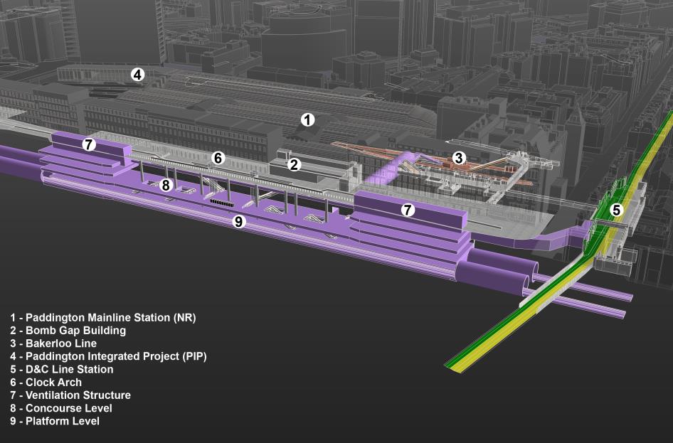
Figure 2: – Schematic graphic showing new structure in context
Geotechnical conditions
The soil profile comprises Made Ground (and some Langley Silt) above River Terrace Deposits over the London Clay.
Limited data shows the London Clay extends to about 60.5 m below Eastbourne Terrace (to elevation 66 mATD) and overlies a thin clayey silt and fine sand layer of the Harwich Formation above the Upper Mottled Beds and Laminated Beds of the Lambeth Group. The elevation of the surface of the London Clay falls from about 122.6 mATD at the west end of the Station box to about 118 mATD at the east. At the east end of the station box there is up to about 4.5 m of River Terrace Gravel above the London Clay.
The River Terrace Deposits become thinner toward the west and appear to be absent at the west end of the station box. Above the River Terrace Gravels the material is predominantly Made Ground. It also appears that the walls supporting Eastbourne Terrace are mainly retaining Made Ground.
As is typical for Central London there are two aquifers beneath the site; a shallow upper aquifer in the River Terrace Deposits and a lower deep aquifer in the Chalk, Thanet Sand and Upnor Formation. The two aquifers are separated by the low permeability London Clay and clay layers in the Lambeth Group.
Programme and interfaces
In addition to these physical constraints, a number of construction aspects, both local to the site and from the wider project, strongly influence the design:
• The proximity of Paddington to Royal Oak Portal from where the first tunnel boring machines (TBMs) were launched means that the tunnel drive passes through the station before perimeter wall installation is complete, and prior to any excavation. These tunnels are required to service the ongoing TBM drive and so must be kept live during all but the final stage of excavation at Paddington.
• Eastbourne Terrace is a heavily traffic part of London’s road. It was decided to close the road completely during the early stages of the programme, but reopen two lanes of traffic after two years, to minimise disruption.
• Handover of the platform area to the system-wide contractor, for works on the Crossrail critical path.
Scheme Development
Preliminary scheme
The preliminary scheme design was taken to RIBA stage C and handed over to URS for further design in August of 2009. This scheme located the station box underneath Eastbourne Terrace, to be constructed using top-down methods.
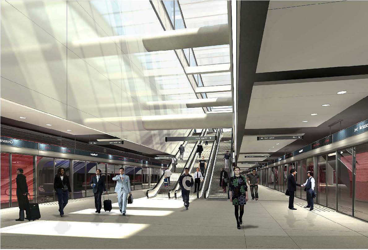
The main station box itself was 264 m long, 25 m wide, 26 m deep, with four permanent slabs propping diaphragm wall panels both during construction and in the permanent case. In the central portion of the station, inclined concrete struts between the main slabs (in back of house areas) formed a ‘structural truss’, transferring vertical loads to the perimeter walls and removing the need for columns at platform level (figure 3). Long voids ran along the box centre line through each of the upper three slabs, creating a ‘light well’ from street level to platform, housing escalators and supplying daylight to the lowest areas of the station. The resultant anticipated view from platform level can be seen in figure 4.
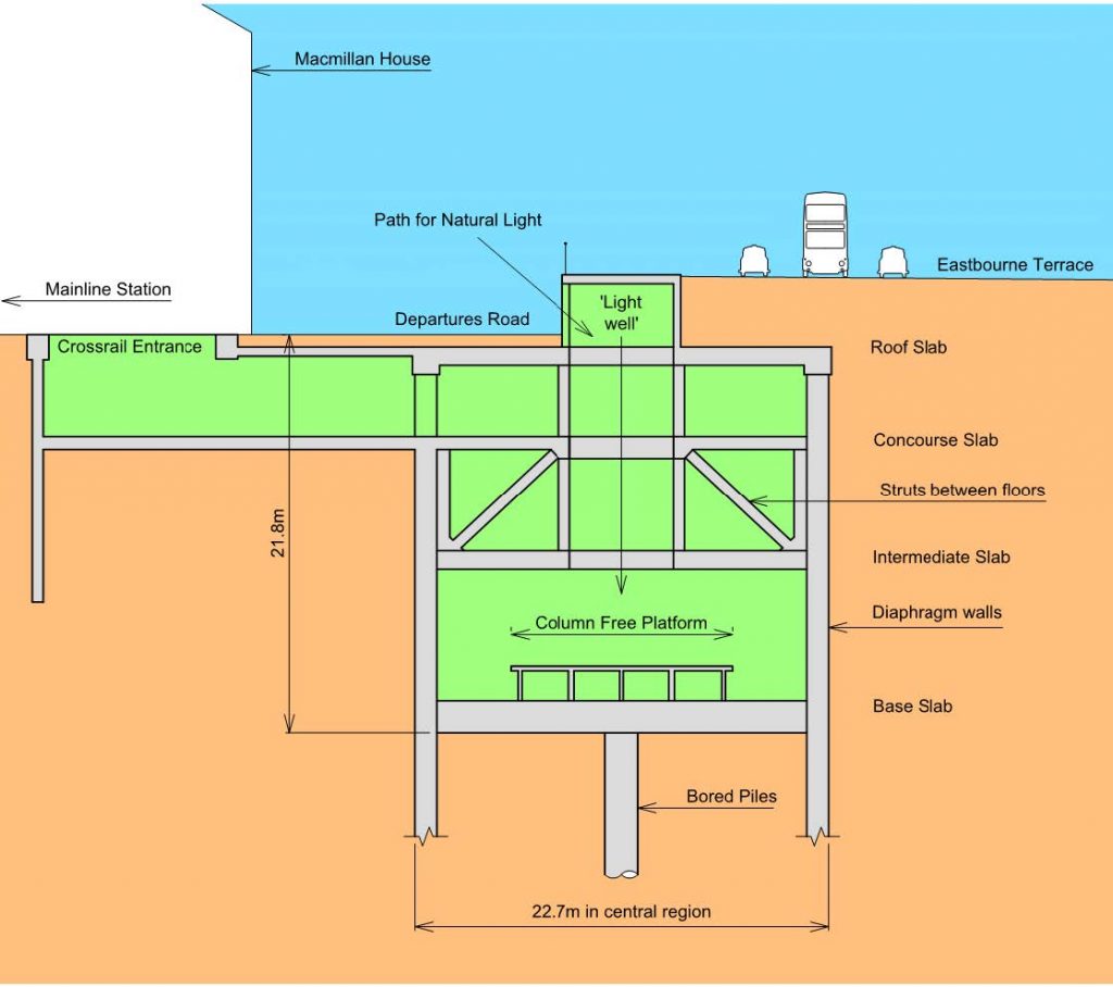
Figure 3: Preliminary design – typical station cross section
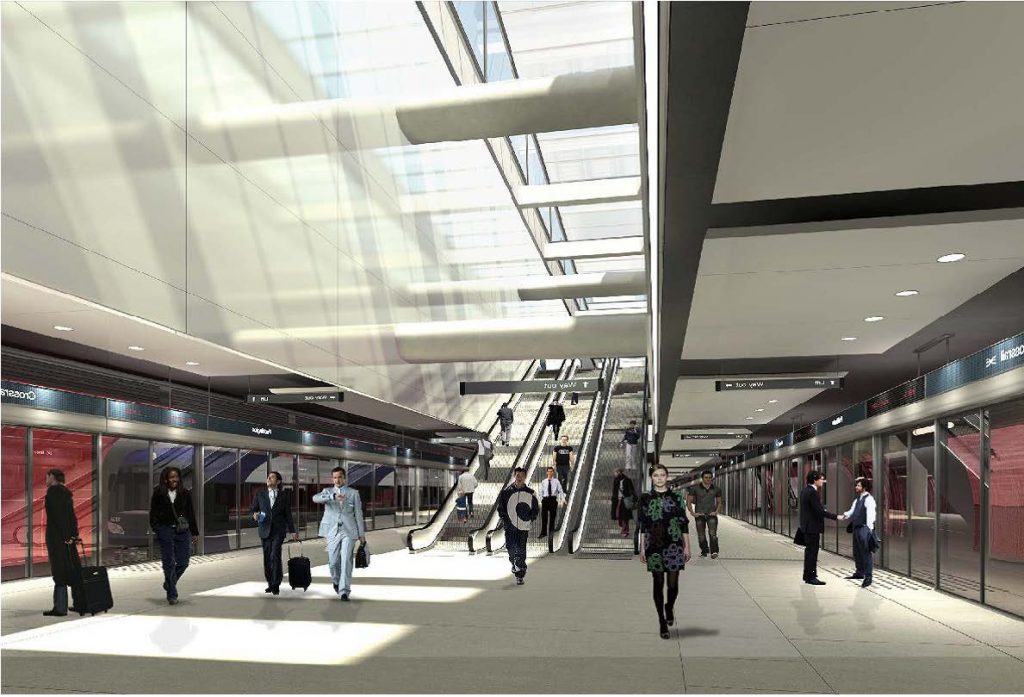
Figure 4: Preliminary design – view from platform
Street level access to the Crossrail station was via an entrance located within the mainline station concourse, behind the bomb-gap area. Passengers descended from the mainline concourse via a bank of escalators, before walking through a link tunnel beneath what is currently the post-war low-rise building, to gain access to the main station box. In order to construct this new entrance and link tunnel, the existing building at the bomb gap would be substantially modified, with large transfer structures introduced to support the structure above the new link. The tunnel would displace existing subterranean toilet blocks and sub-station ‘N’, both therefore relocated and demolished as part of the works.
Access to the LU Bakerloo line was proposed via a bored tunnel from the new concourse level which passed beneath the mainline station, 7 m below ground. A cut and cover link from the eastern end of the main box, underneath Praed St, would connect the new station to the District and Circle Lines.
Departures Road scheme
Whilst taking this preliminary scheme through the RIBA Stage D phase, URS, Weston Williamson and Crossrail worked together to develop an alternative design, known as the ‘Departures Road Scheme’ (DRS). It was recognised from the outset that this alternative could potentially deliver improvements over the preliminary design, and so both the original scheme and DRS were progressed simultaneously to RIBA stage D.
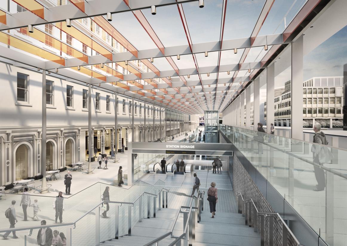
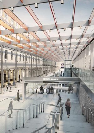
The most significant change in the DRS was to move the street level entrance out of the mainline station, locating it instead within Departures Road itself. This eliminated the need both for construction within the mainline station, and major rework of existing buildings in the bomb gap area, as the link tunnel was no longer required. In addition, a glazed lightweight canopy was proposed above the new Departures Road entrance. This provided cover above the Crossrail access and created an ‘urban realm’ between the mainline and proposed stations. Figures 5 and 6 summarise the revised form.
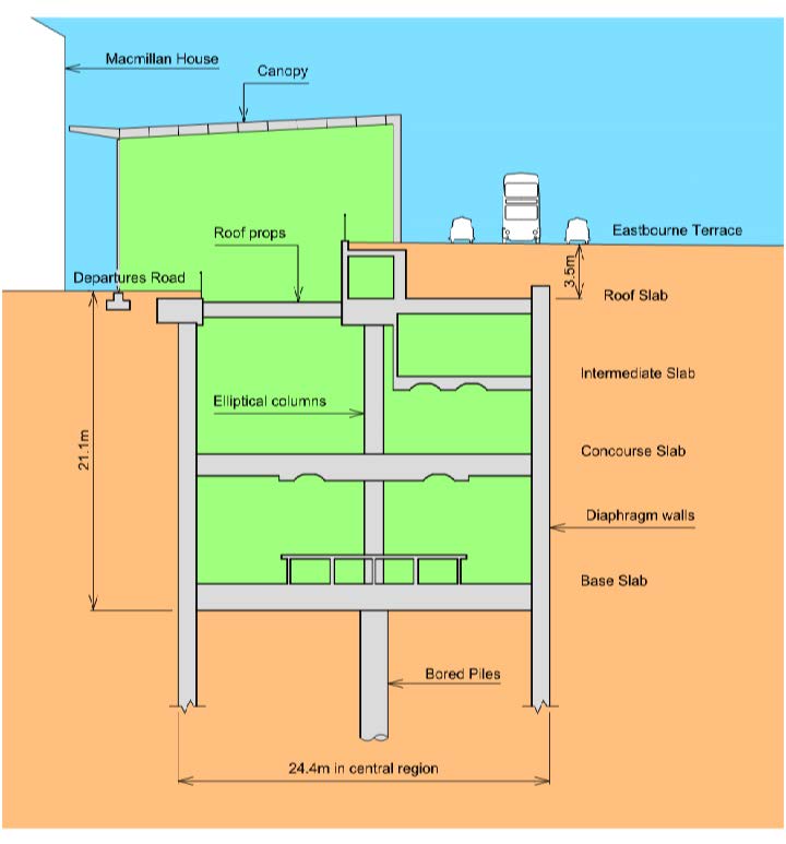
Figure 5: Final design – typical cross section
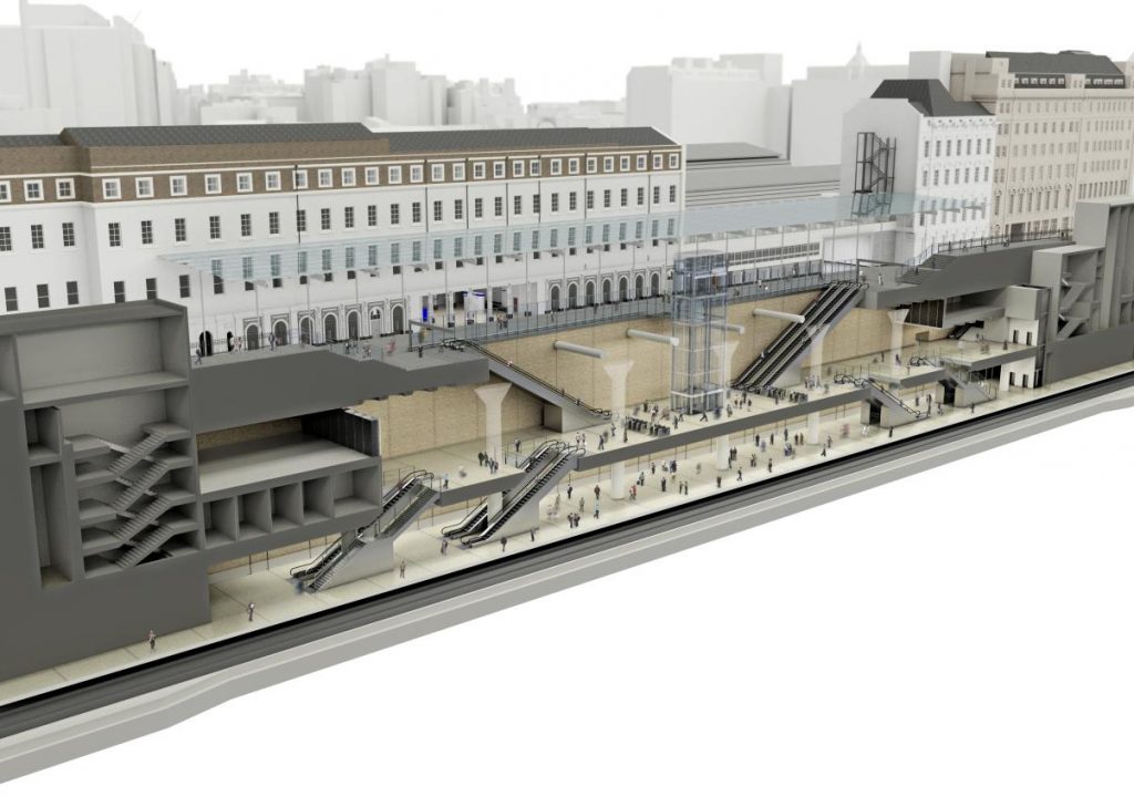
Figure 6: Final design axonometric view
By progressing both schemes to RIBA stage D, a fair comparison could be made between the two. It became clear through this process that the DRS provided significant benefits, including:
• Improved passenger comfort by reducing the time spent, and distance travelled, underground.
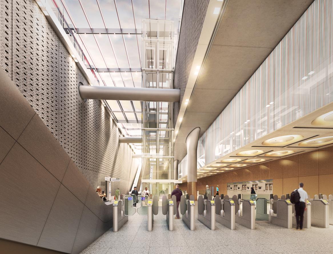
• Improved passenger experience as the Departures Road entrance and canopy create a grand ‘atrium’. Passengers entering the station will enjoy direct line of sight from street level to the gate lines below, whilst those ascending from the platforms will emerge into a large, airy, naturally lit space. See figures 7 and 8.
• Columns are reintroduced in the central region of the station box, removing the inclined struts between slabs and therefore providing more space back of house for equipment and circulation.
• Less disruption to the mainline station during construction as no excavation is required for the entrance within the existing concourse.
• No link tunnel now required so demolition of the toilets and sub-station ‘N’ are no longer required. The major structural works in the bomb gap building are replaced by a refurbishment to accommodate the entrance from Departures Road to the man line station.
• Substantial cost savings as a result of all the above.On this basis the DRS was identified as the preferred option and was progressed to detailed design and construction.
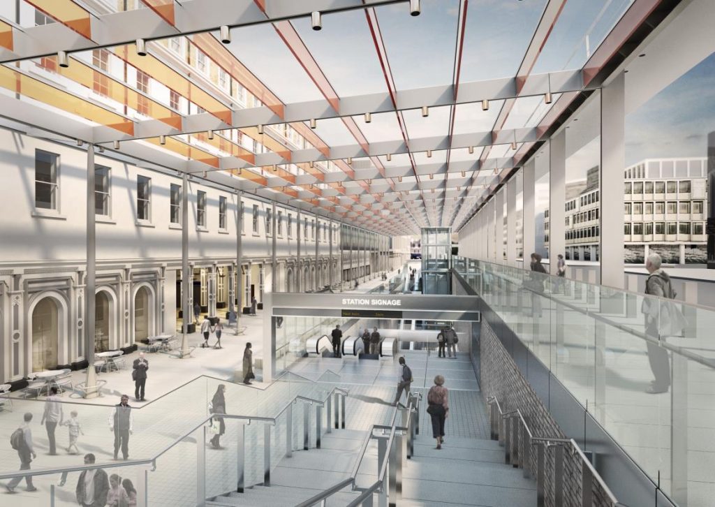
Figure 7: Final design – view of entrance and canopy structure

Figure 8: Final design – view from concourse
Further developments generally did not affect scope with the exception of the link tunnels to LU stations. Following a Crossrail value engineering review in 2011 the District and Circle line link was replaced by passive provision for a future tunnel. The Bakerloo line link was temporarily put on hold and ultimately lowered, as the initial proposed tunnel was located very close to the top of the clay layer and passed in close proximity to the Macmillan House and Brunel shed foundations.
Final Design
Passenger Experience
Despite the developments of the DRS, the overall station geometry and location are similar to the preliminary design stage. The main station box is in the same position, underneath Eastbourne Terrace and Departures Road. Overall plan dimensions are unchanged from the preliminary design, although the excavation depth is reduced by a about a metre. Existing street levels across the width of the station will be restored, with Eastbourne Terrace to the south up to 3.5 m higher than the urban realm at Departures Road.
Passengers descend into Crossrail from street level via a 65 m long void in the station roof, with banks of escalators at either end. These terminate at concourse level some 11 m below ground. Four circular concrete props traversing the roof slab penetration form the only structure between the glass canopy roof and the concourse-level gate lines (see figure 8). From concourse, escalators located along the box centre line provide transit to and from the platform level below.
The effect of this arrangement is to provide passengers entering the station with a pleasant, grand entrance and a sense of space whilst descending to concourse level. Similarly those exiting the platforms ascend into a large ‘entrance hall’ with unimpeded sight lines from concourse to the canopy roof 20 m above, and sky beyond. For passengers in both directions, the wayfinding afforded by the DRS is much clearer and so transit is less stressful.
Departures Road Canopy
The newly developed area in Departures Road (seen in figure 7) is covered by a lightweight steel-framed glass canopy spanning transversely from the change in street level to the mainline station, but remaining independent from the existing, listed buildings. This structure provides cover to the central stretch of the urban realm, and pedestrian route between Crossrail and mainline stations, whilst maintaining an open space flooded with natural light.
The structure itself is planar: 122 m long and 23.29 m wide, with a main span of 18.2 m (perpendicular to Departures Road). The canopy is a minimum of 9.75 m above the Departures Road level and 7.1 m above the Eastbourne Terrace pavement.
Primary structural elements are on a 6.11 m grid, derived from the MacMillan House arcade. The main beams are fabricated H-shaped hollow sections spanning between H columns founded on the upstand structure of the main box along Eastbourne Terrace, and slender circular columns set back 2 m from Macmillan House.
Longitudinal stability is provided through the base moment contribution of the columns adjacent to Eastbourne Terrace, and the roof acting as a plan vierendeel truss in order to distribute any horizontal loads. Secondary longitudinal framing members (parallel with Eastbourne Terrace) consisting of 550 mm deep by 30 mm thick glass fin beams are at 1.9 m centres and provide lateral torsional buckling resistance for the main frame members.
Structural Slabs
As with all top-down construction, the reinforced concrete floor slabs at each level serve to support vertical load and transfer horizontal soil propping forces throughout the full life of the structure, including construction. At Paddington four such slabs are provided:
• Roof slab below street level, 1000 mm thick.
• Intermediate slab, 900 mm thick.
• Concourse slab housing ticket offices and gate lines, up to 1750 mm thick.
• Base slab, 1750 mm thick.At either end of the station box each of these slabs act to prop the walls and so resist horizontal forces. However in order to provide the desired entrance from street level, an alternative solution is required over the central 92 m of the structure, with a different propping arrangement.
At roof level the four props described previously provide the solution. The position of these props directly below the existing ground level allows for provision of a large waling beam along the northern edge of the entrance, below the street. This beam spans horizontally, transferring soil propping loads between the four circular props and thus to the southern side of the excavation, where the roof slab itself acts as a deep, internal waling beam. The one metre diameter concrete props are precast, to provide the high quality finish demanded by their prominent position.
The ‘intermediate’ slab, providing back of house areas for plant and staff, is bypassed by passengers travelling on the escalators between street level and concourse. In order to provide direct passage from street to concourse the intermediate slab is half-width in the central part of the station. In fact the slab stops short of the main central columns in this area; it is supported by the southern wall on one side and on the other by hangers anchored into the roof slab. The result, as can be seen from figure 8, is to give users an uninterrupted view of the main columns extending from concourse to roof level, mirroring the climb of the large entrance escalators. In this area therefore the intermediate slab does not act to prop the walls which span instead from concourse to roof.
Further down, the concourse slab provides transverse propping for the full length of the box. The resultant horizontal loads are significantly increased in line with the entrance, where the intermediate slab does not contribute. As a result the slab depth here is increased to 1750 mm, from 1000 mm in the rest of the station. Voids in the slab along the box centre-line accommodate stairs and escalators to and from platform. The remaining slab area either side acts as an internal deep waling beam, distributing the soil loads around the voids.
Soffits of the elevated slabs will generally be fair faced concrete. In areas accessible to the public, intermediate and concourse slab soffits are coffered, with a curved profile resulting in a ‘spherical cap’ of 420 mm depth removed from the slab, at 3.055 m centres (figure 9). These coffered profiles enable lighting to be recessed into the slab itself, increasing the proportion of reflected light and thus reducing glare. Structurally they serve to reduce the dead load of the slab whilst maintaining the overall depth and so produce an efficient section for bending. The coffered profile will be formed using precast panels, ensuring a high quality of finish for these exposed elements.
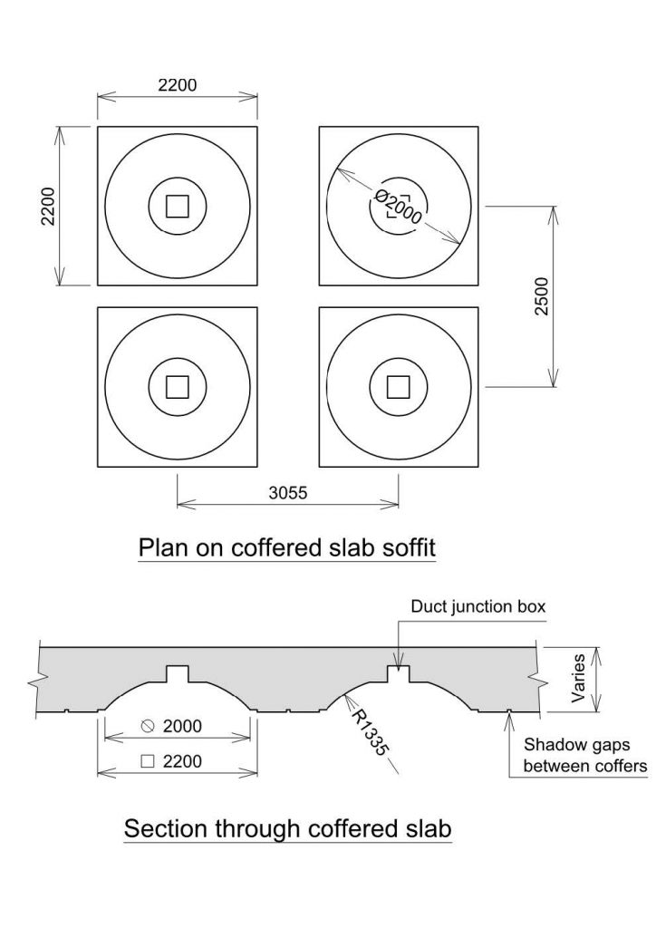
Figure 9: Coffer details at intermediate and concourse slabs
The base slab plays a relatively minor propping role as a result of the top-down sequence of construction, which loads the suspended levels to a much higher degree. Predominantly this deep slab therefore works to resist uplift forces (from water pressure and heave) by bending between diaphragm walls via the central row of piles. The slab itself is penetrated only by sumps at either end of the box, and the local excavation providing access to the Bakerloo line link.
This link, lowered by 12 m since the preliminary scheme, takes passengers down from platform level via escalators and stairs, to a tunnel passing underneath the track and through the diaphragm wall, before travelling beneath the mainline station in a 4900 mm diameter sprayed concrete passageway to the Bakerloo line platforms.
This lowered alternative provides a more direct route for passengers and reduces impact on the historic structures above.Vertical Elements
In the central portion of the station, accessible to the public, a single row of elliptical columns is provided spaced at 18.33 m centres, with oversized flared column heads below the roof slab. The column section is 1250 mm wide throughout, and 1800 mm long increasing to 6200 mm at the head. By providing a solitary row of central columns on such a large grid, platform space is maintained and these elements possess a sense of grandeur which compliments the public areas through which they pass (see figure 8). The elliptical shape provides structural efficiency in bending and against buckling, whilst maintaining a softer aesthetic. The column heads, fundamentally required to provide punching shear resistance at roof level, are sized beyond the structural requirements in order to maintain a sense of proportion responding to the scale of the surrounding elements.
The reintroduction of columns as part of the DRS delivers a number of benefits. The inclined truss members between floors are removed, which increases accessible space for back of house areas and thus makes the most effective use of the slab footprint. The columns provide a simpler structural form, which makes for simpler detailing and reduced reinforcement congestion. Primarily however the multi-level entrance could not be accommodated with the structural layout from the preliminary scheme, and so once again the most obvious benefit is the improved passenger experience.
At the station ends, in back of house areas, the single row is replaced by pairs of columns with a reduced spacing, typically between seven and ten metres. This arrangement suits the requirements in these areas for numerous large slab penetrations accommodating plant and ventilation equipment. One metre square columns are provided in these regions, where visual impact is less of a concern.
Vertical loads around the perimeter of the structure are carried by diaphragm walls which also retain the ground in the temporary and permanent conditions. Diaphragm walls are stiffer and stronger than secant piles of the same thickness, and therefore better suited to this site with existing structures in close proximity. Typically the panels are 1.2 m thick, although at the box ends this reduces to 1.0 m to provide the necessary TBM clearances. The walls extend twenty metres below the base slab, working with the central bored piles to resist long term uplift forces and prevent flotation.
Above ground, the existing Eastbourne Terrace level will be restored during construction. Various alternatives were considered but clearly to minimise disruption to road alignments and thresholds of existing buildings the most favourable solution is to maintain the current ground profile. Two approaches to restoring this level are combined, minimising the impact on the roof slab, 3.5 m below the road:
• Where headroom requirements allow, concrete structures are provided on top of the roof slab, underneath the road. These provide usable space and access routes, whilst significantly reducing the volume of fill supported by the slab.
• Elsewhere lightweight fill is used to minimise loading on the slab. Standard fill is provided for the top metre, the rest made up using lightweight expanded clay aggregate.The Eastbourne Terrace level will be restored after completion of the roof and prior to excavation, in order to open the road to traffic. Therefore these reductions in structural weight above ground yield material savings not only in the permanent slabs and columns but also in the size of plunge columns and piles required during construction.
Construction
Top down Methods
Two factors drove the decision to construct the main station box using top down methods. First, top down construction is stiffer, with smaller wall movements, minimising damage to the surrounding buildings and utility corridor. Second, the desire to reopen Eastbourne Terrace to traffic as early as possible required the roof slab to be constructed at the front end of the construction programme.
Diaphragm walls provide soil retention during the bulk excavation, propped by the permanent slabs. The walls are constructed in panels of 3.35 m width, excavated under bentonite to maintain stability during the two-day construction process. At its heaviest the reinforcement in these panels consists of two layers of 50 mm diameter bars, using couplers to eliminate laps and reduce congestion. Steel stop ends form construction joints between panels and retain concrete during the pour. Diaphragm walls are installed with a verticality tolerance of 1:200, using a hydraulic grab. Figures 10 and 11 show the plant in the context of the narrow site.
Figure 10: Photograph showing diaphragm wall plant on site
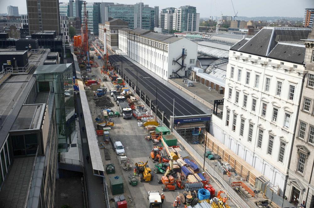
Figure 11: Construction site as mid 2012
During excavation vertical support to the slabs is provided in part by the diaphragm walls and in part by steel plunge columns. Forty-nine such columns support the slabs along the box centre line, typically spaced at 6.11 m longitudinally. All columns are 550 mm square H-sections, with web and flange plate thicknesses varying from 25 mm to 40 mm and 50 mm to 70 mm , respectively, dependant on column location. These steel columns, approximately 23 m long, are installed to a verticality tolerance of 1:400 and supported by 1800 mm diameter piles below the base slab level, founded 60 m below ground. Upon installation of each plunge column the surrounding pile bore is backfilled with pea gravel.
Design of the columns used finite element models and eigenvalue analysis to establish buckling loads for each element, at every stage of construction. Backfill around the column was conservatively assumed to provide no lateral restraint to the column. To limit the effective length during early stages therefore, two 500 mm thick insitu concrete discs are cast at designated levels during the bore backfill to provide temporary lateral restraint. This reduction in effective length enables smaller sections to be used and thus delivers material savings.
At eight locations, where plunge and permanent columns coincide, the steel section is retained and acts compositely with the insitu elliptical concrete section cast around it, to support the station in the permanent case. All other plunge columns are removed once the concrete elements are constructed, and load is transferred to the permanent works. The supporting piles however are tied to the base slab and provide long term resistance against heave and flotation. Thus the pile design in the short term is governed by downward forces but in the long term by uplift.
The intermediate slab is not constructed top down, but replaced with temporary steel struts and waling beams during the bulk dig and cast on formwork later in the programme. This accelerates excavation and protects the running tunnel lining as described in the next section.
Tunnelling interface
The tunnel drive passes through Paddington during construction of the diaphragm walls, so this interface is key to both the station and tunnelling contracts.
At the eastern end of the box a soft ‘eye’ is provided which the TBM can break through. This involved constructing full depth panels but casting the lower sections using an unreinforced cement/bentonite mix. However more recent analysis has shown that the clay at this depth is sufficiently cohesive to be self-supporting, until a permanent reinforced ‘collar’ is cast around the tunnel lining. At the west end therefore, which was constructed later, panels forming the return are stopped short of the tunnel crown, leaving uninterrupted clay below through which the TBM can pass.
The interaction between the station and tunnelling programmes creates a particular constraint for the construction sequence at Paddington. The TBM passes through the station box prior to excavation, but the running tunnels must be kept live in order to service the ongoing tunnel drive further along the line, for as long as possible. This is achieved using the following sequence of excavation:
1. Perimeter walls, plunge columns and roof slab completed.
2. Excavation to 3 m above crown of tunnels.
3. Install steel propping frame, with struts preloaded to 700 kN/m. This relieves the horizontal soil pressure on the tunnel lining, just as excavation has relieved the vertical pressure.
4. Excavate to concourse slab soffit, 500 mm above tunnel crown.
5. Construct concourse slab on blinding.
6. Construct intermediate slab on formwork and remove steel props.
7. Running tunnels handed over to Paddington contractor.
8. Excavate below concourse including demolition of tunnel lining within station length.Detailed analysis, in conjunction with the running tunnel designers, has been undertaken in order to demonstrate that this sequence can be accommodated by the lining segments, without the need for internal propping (which would restrict movements up and down the tunnel).
Existing structures
A major benefit of the DRS is the reduced degree of construction required within the existing mainline station and Macmillan House footprint.
Some works of course are still required. 800 mm of the Macmillan House basement outer wall must be removed by wire-cutting, in order to make space for the diaphragm wall installation. In addition to this the entrance between Departures Road and the main line station will be refurbished to accommodate the predicted increase in passenger flows.
This however is significantly less than originally anticipated by the preliminary scheme, which required piling and excavation for an entrance and tunnel between the mainline and Crossrail Stations. In the DRS the subterranean toilet blocks, and substation N, remain in use, saving significant demolition and diversion costs. The additional transfer structures designed above the entrance, to allow removal of Macmillan House foundations, are also no longer needed.
The net result therefore is a much simpler interface with these structures and associated stakeholders, and far less disruption for the users of both Macmillan House and the mainline station.
Conclusion
Rarely are designers presented with the opportunity to design new structures in the heart of London, in locations with constraints and heritage as substantial as those at Paddington. As can be seen from this discussion however the primary drivers and constraints remain the same as for any major civil project. The design at Paddington is driven by passenger experience and the client’s needs, by programme and value, and by the existing environment and infrastructure.
At each stage such considerations have dominated the design, with every discipline individually and collectively developing solutions which respond to these requirements. The final design, and in particular the changes implemented through the alternative scheme, deliver improved solutions for the client and passengers alike. A coordinated approach between stakeholders and design disciplines has produced an efficient, elegant solution which seeks to provide all users with an exceptional experience, adding value both during construction and for many decades to come.
-
Authors

Richard Scantlebury MEng MA(Cantab) CEng MICE - URS
Senior Engineer, URS
Gerard Brennan BE MSc DIC CEng MIStructE - URS
Lead Structural Engineer for Paddington Station, URS
Mark Raiss MA MSc DIC PhD CEng FICE FIStructE FCS - URS
Crossrail Programme Director, URS