Development of two different station designs – a comparison of Paddington and Farringdon Stations
Document
type: Technical Paper
Author:
James Paterson MA MSc DIC CEng FICE MIStructE CPEng FIEAust, Mark Raiss MA MSc DIC PhD CEng FICE FIStructE FCS, ICE Publishing
Publication
Date: 03/11/2014
-
Read the full document
INTRODUCTION
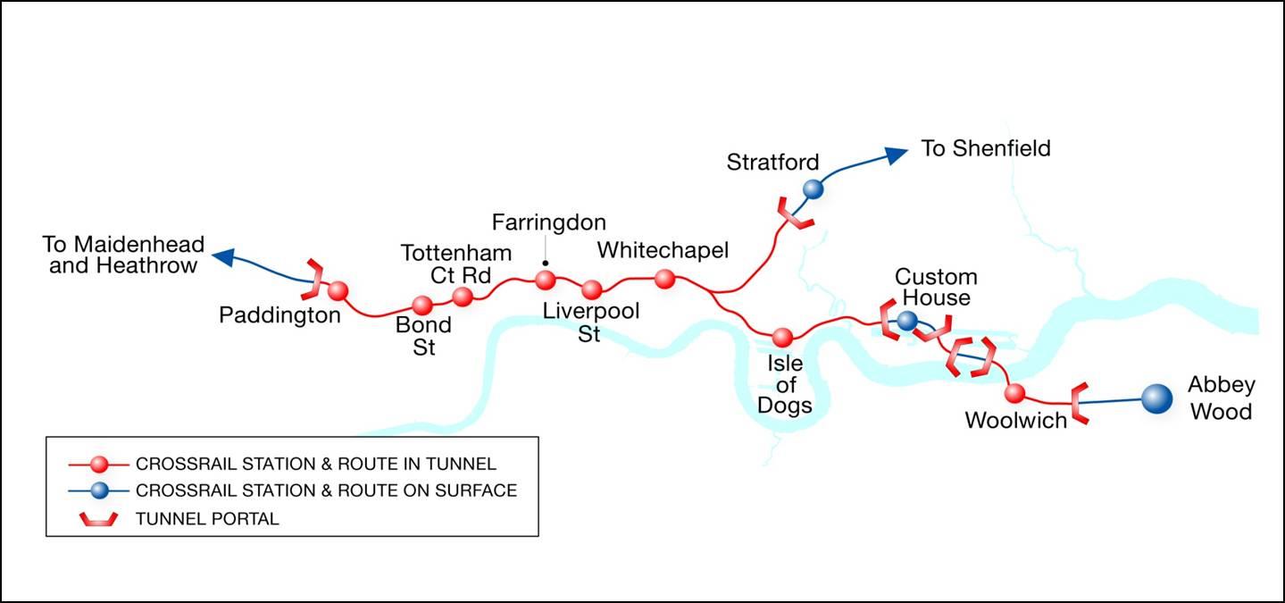
Crossrail Central includes 21km of new twin bore tunnels through central London and the construction of eight new underground stations, plus one new surface station. [Figure 1]. The purpose of this paper is to describe a number of key design features of the two underground stations at Paddington and at Farringdon. They have been selected as they are both to be constructed on constrained sites in central London adjacent to historic buildings. They both form key interchange stations and both have to address many of the same fundamental design issues. However there are major differences in layout and in the form & sequence of construction which are a direct consequence of their particular location and other constraints.

Figure 1 Crossrail central section
Also, while the two stations are more than 3 miles apart, they are connected in terms of the tunnelling works and the tunnelling construction programme, which have a significant impact on the design solutions.
This paper:
• Outlines some of the key design issues
• Describes the location and constraints of the two stations
• Explains how the two stations address particular key design issues
• Provides a table of key differences
• Shows how the solutions adopted are both appropriate and cost-effective.This paper concentrates on the civil & structural engineering aspects. The authors hope that this broad summary will be of assistance to designers of similar projects. In preparing this paper, it has been assumed that the reader is familiar with the key features of the overall Crossrail Project.
Paddington Station is the subject of a separate paper – which covers the design in detail; this paper therefore only outlines certain features of the design of Paddington to allow comparison with Farringdon Station design.
KEY DESIGN ISSUES
Summary
There are very many different factors that need to be considered in the design process. However, for the purpose of this report, the relevant factors are taken to be:
• Adjacent existing structures / urban context
• Rail infrastructure connections
• Oversite developments
• Integration with tunnelling works
• Ground conditions
• Form of wall construction
• Sequence of construction
• SpaceproofingThe final design of both stations is driven by safety, buildability, physical constraints and the need to provide a station appropriate to its location and historical setting. The key design objective has been to provide the travelling public with an excellent passenger experience while providing Crossrail with a design that offers value for money and that can be built safely within the overall Crossrail programme.
While this report concentrates on civil & structural design issues, the authors wish to emphasise that all disciplines have worked collaboratively with each other, as well as with Crossrail, third party stakeholders and contractors, to develop solutions which respond to these constraints and drivers. The decision to co-locate the design teams with the Crossrail client has been important in fostering this spirit of co-operation.
Adjacent Existing Structures / Urban Context
Both stations are to be constructed in densely populated areas on restricted sites and adjacent to listed buildings. Limiting ground movements is a key to minimising the risk of damage to adjacent properties, utilities and infrastructure. This is particularly important for safety-critical items such as certain utilities, London Underground or Network Rail lines, as well as for historic structures.
Rail Infrastructure Connections
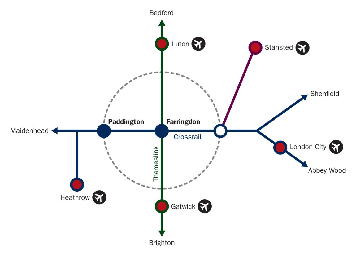
Both Paddington and Farringdon Crossrail Stations form key interchanges to London’s existing rail infrastructure.

Figure 2 Key transportation links
Paddington Crossrail Station, the most westerly of the Central Stations, links in with Network Rail’s terminus station at Paddington, as well as providing a direct link to London Underground’s (LU’s) Bakerloo Line.
Farringdon is located centrally in the heart of London. As well as providing links to the Circle, Hammersmith & City and Metropolitan LU lines, it also forms a major interchange with Thameslink – the only other cross-London mainline railway. On completion, Farringdon Station will provide direct rail links to four of London’s five airports.
Oversite Developments (OSDs)
Part of the funding for Crossrail is derived from commercial OSDs, which also play an important role in re-establishing the built environment.
At Paddington Station there is no OSD directly above the station, while at Farringdon there are two OSDs, one above the West Ticket Hall (WTH) and one above the East Ticket Hall (ETH).
The significance is that Paddington Station represents a completed, final architectural statement, while at Farringdon both sites rely on the subsequent OSDs for their full integration into the urban settings.
Integration with Tunnelling Works
One of the key design considerations for any underground station is the way it integrates with the tunnelling works – both the permanent structural connections and the construction phase (including the dismantling & removal of the Tunnel Boring Machines (TBMs)).
Platforms are typically either
• formed within a cut-and-cover box [Paddington], or are
• constructed as mined tunnels using Sprayed Concrete Lining (SCL) construction techniques [Farringdon]The choice of construction methodology depends on the alignment of the tunnels and the depth of construction. At Paddington, the depth from existing road to top of rail level is approximately 21m, while at Farringdon Station the depth varies from 27m to 32m.
Five twin-bore tunnels are to be constructed. Two of these twin-bore tunnels (X- and Y-Drives) affect the construction of Paddington and Farringdon Stations:
• The X-Drive (6.4 km long) commences at Royal Oak portal, just to the west of Paddington Station, proceeds in an easterly direction and terminates at Farringdon
• The Y-Drive (8.3 km long) commences at the Limmo shaft in east London and proceeds in a westerly direction also terminating at FarringdonConsequently Farringdon Station is the termination point for two drives (ie 4 TBMs) and has to accommodate their arrival, decommissioning and removal. Paddington Station is near the start of the X-Drive, and consequently the sequence and method of construction of the station has to accommodate the passage of two TBMs through the station box relatively early in the station’s construction sequence.
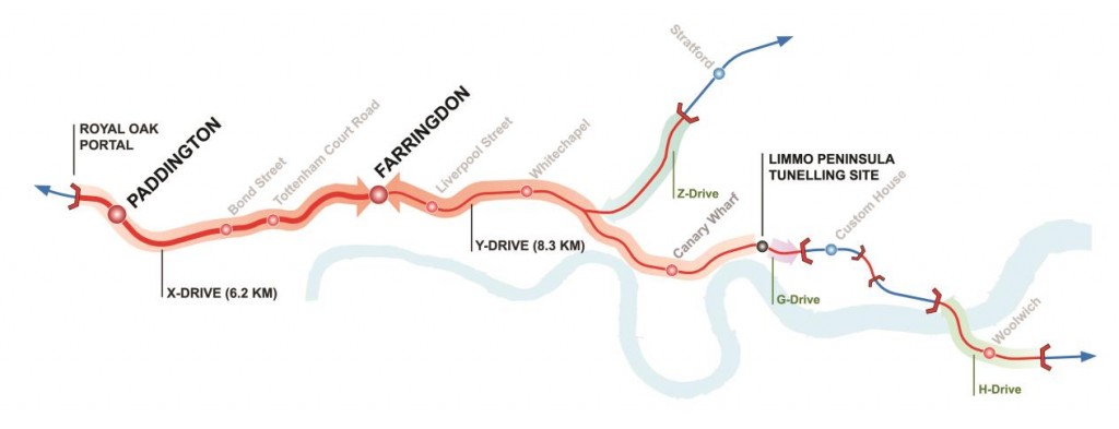
Figure 3 Crossrail central tunnelling drives
Ground Conditions
The ground conditions at the two stations are very different.
At Paddington, London Clay exists at shallow depth and extends well below the base of the excavation. These favourable ground conditions are beneficial to the tunnelling operation and can be exploited in the box construction methodology.
By contrast, at Farringdon, the ground is very complex and heavily faulted, with London Clay overlying Lambeth Group and Thanet Sands. Although, in terms of ground water levels, the site is under-drained at depth, there are perched water tables and water-bearing gravels which pose particular problems for the construction of mined SCL tunnels. [Figure 4] These ground conditions have had a major impact on the tunnelling strategy and a direct impact on the size, location and sequence of construction of the shafts.
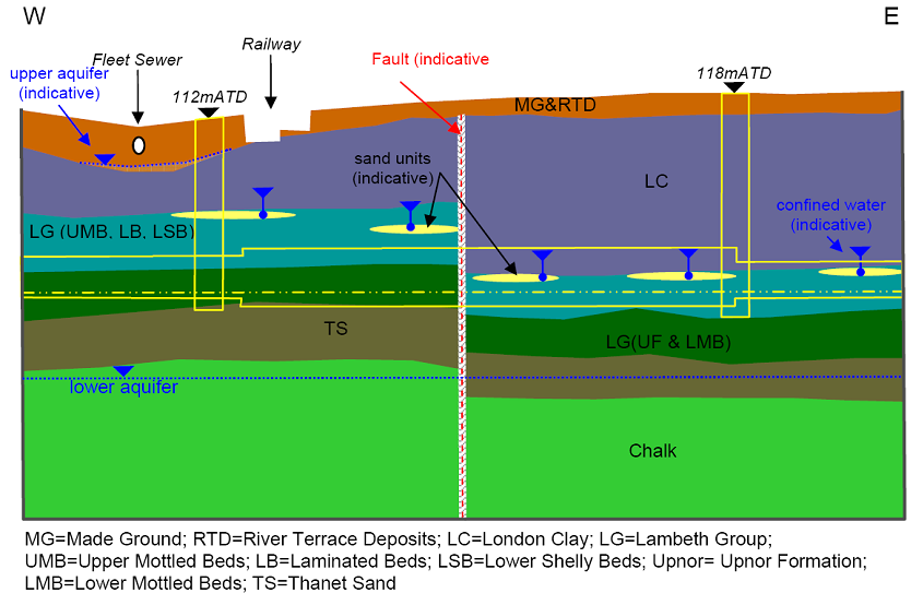
Figure 4 Farringdon diagrammatic geological section
Wall Construction
Deep basement construction is a feature of most Crossrail Central stations, whether in the form of a single cut-and-cover box or a series of discrete shafts & boxes.
While many methods of construction exist, perimeter walls are typically either
- diaphragm walled panel construction or
- secant or contiguous bored-pile walls.
While diaphragm-walled construction can offer considerable advantages, the size and type of plant means that it is not suitable for all sites.
Sequence of Construction
The sequence & method of construction for shafts and underground boxes is usually described as either “bottom-up” or “top-down”.
[These terms refer to the sequence in which the permanent works are cast within the perimeter walls, ie:
“Bottom-up” construction is when temporary propping (eg – steel frames or temporary anchors) is used to support the perimeter walls as excavation proceeds down to the bottom. The bottom levels of permanent works slabs are therefore constructed first and the other levels are constructed progressively upwards.
“Top-down” construction is when the upper level, permanent works slab is cast first, and the lower levels are constructed progressively as excavation proceeds. The slabs prop the perimeter walls as excavation proceeds and act as both permanent and temporary works props (ie the permanent works are constructed from the top down).] [Figure 5]
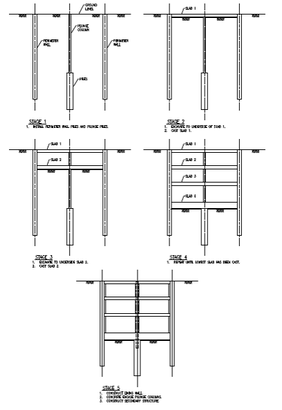
Figure 5 Top-down construction sequence
Either sequence of construction can be used with diaphragm walled or contiguous / secant bored pile wall construction.
Generally top-down construction is better at controlling ground movements. The top slab (which is cast first) can provide useful layout areas on congested sites and/or allow road access to be reinstated. While time to complete all of the permanent works can be similar for either method, the time to reach the base of the excavation using temporary steel props in bottom-up construction is usually quicker.
A feature of top-down construction is the use of plunge columns – steel columns plunged into bored piles to carry the weight of the slabs as excavation proceeds. Plunge columns can either be temporary (removed after construction of the permanent columns & walls), or permanent (cast into the permanent walls or columns).
Because the slabs are typically cast on the ground, there is a great advantage in simplifying the soffit shape and a flat soffit is generally preferable to a beam and slab arrangement. A clear route for horizontal loads in both the temporary and permanent condition is required.
Spaceproofing
The layout and configuration of a railway station has to respond to a complex range of requirements and constraints.
For deep underground stations, space-proofing is of particular importance. In addition to passenger flows, vertical circulation and associated space requirements, one of the key considerations is the space-proofing associated with tunnel ventilation, service risers, means of escape and fire-fighting access. Tunnel ventilation, in particular, requires risers with large cross-sectional areas and with a limited number of bends – with large fans requiring access for maintenance, repair and replacement.
Ultimately the purpose of the Crossrail project is to serve the travelling public. Key to that is to create routes with intuitive way-finding to improve the passenger experience for all users and to cater for growth in passenger demand. This has a big impact on the volumes and spaces created and hence on the structural layout.
STATION DESCRIPTIONS
The following descriptions should be read in conjunction with the following figures [Figures 6, 7, 8 & 9], which provide a direct visual comparison between the two stations.
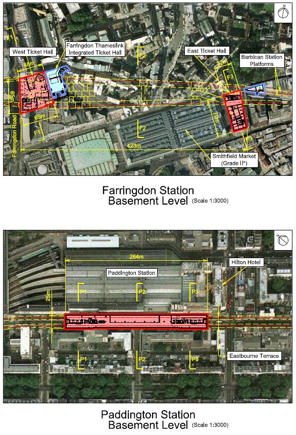
Figure 6 Farringdon and Paddington plans at basement level
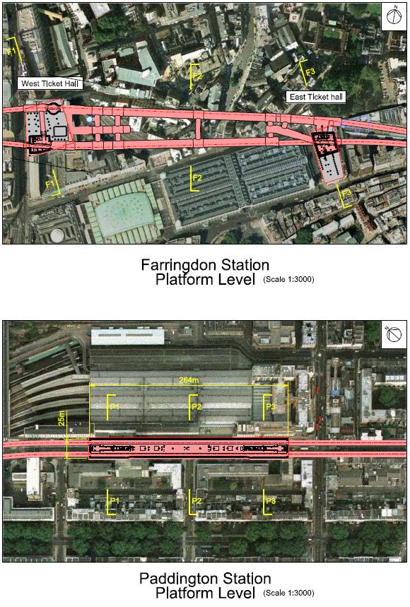
Figure 7 Farringdon and Paddington plans at platform level
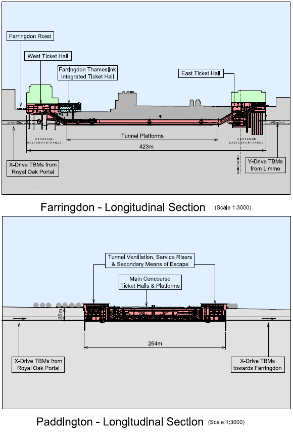
Figure 8 Farringdon and Paddington longitudinal sections

Figure 9 Farringdon and Paddington cross-sections
Paddington Station
Context
Paddington Crossrail Station is to be constructed under Eastbourne Terrace immediately adjacent to Paddington mainline station.
Paddington mainline station is the London terminus for frequent long-distance high-speed trains to the west of England as well as for local suburban trains, and is housed in Isambard Kingdom Brunel’s historic shed which dates from 1854 and is Grade I listed. Macmillan House, a terrace adjacent to Eastbourne Terrace is also Grade I listed, while the Hilton Hotel building which fronts Paddington Station is Grade II*.
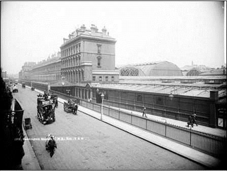
Figure 10 Paddington historic photograph of Eastbourne Terrace
As noted above, there is no oversite development directly above the station (although there is the option for an oversite development above the “bomb gap” in Macmillan House in the future). The design of Paddington station therefore creates a single architectural entity, the design of which needs to sit sensitively alongside the existing Grade I building.
Although, like other Crossrail Central stations, Paddington is to be constructed on a constrained site, it does have the benefit that the entire station can be constructed beneath an existing road, Eastbourne Terrace. The complete station, including ticket hall, concourse, platforms etc can therefore be contained within a single rectangular box at a relatively shallow depth.

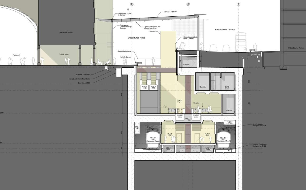
Figure 11 Paddington typical cross-section
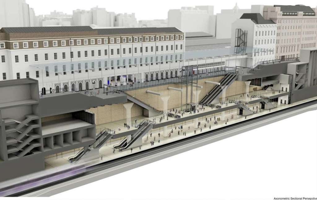
Figure 12 Paddington cut away section
(In contrast, at Farringdon, there is a split site; tunnel platforms are therefore required at considerable depth, as the platforms are located below existing buildings and infrastructure.)
Station Features
Some of the key features of the Paddington Station design are summarised to allow comparison with Farringdon Station – which is described in greater detail below.
There is a single island platform at track level for eastbound and westbound trains, with evacuation cores and ventilation & services risers at each end. The structure comprises a single elongated box running parallel to the existing mainline station (external dimensions 264m long x 25m wide). The large central void houses the two main escalator inclines. The concourse is protected by a glass canopy which replaces the existing Grade I listed canopy.
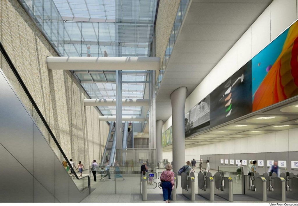
Figure 13 Paddington concourse image
There is a central row of 1800 x 1250mm elliptically shaped columns at 18.33m centres. The roof slab is just below ground level and the general excavation depth is approximately 24m below Eastbourne Terrace.
Form of Wall Construction / Sequence of Construction
The box is to be constructed top-down using 1.0m and 1.2m thick diaphragm wall panels around the entire perimeter. At each end of the box, the diaphragm wall is stopped short to allow the subsequent tunnelling works. The total length of diaphragm wall is 575m, and the typical depths are 40m.
Top-down construction is used to limit movements of the adjacent Grade I listed buildings and to allow Eastbourne Terrace to be reinstated at the earliest opportunity.
The primary slabs (roof, intermediate, concourse and base) prop the diaphragm walls both during excavation and in the permanent case. One level of temporary steel propping is required at an intermediary level to control movements and reduce bending moments, and to limit stresses in the already constructed tunnel linings. These props are removed after casting the concourse slab. The 1750mm deep base slab acts as a raft foundation for the columns and walls and also resists the upward loads due to long term hydrostatic pressures and soil heave. The base slab is connected to a central line of tension piles and the diaphragm walls, which resist the upward loads.
Integration with TBM construction
The method and sequence of construction has been integrated with the planned tunnelling works. The strategy adopted for Paddington station is to construct critical sections of diaphragm wall in advance of the arrival of the X-Drive TBMs. This avoids the risks associated with constructing the diaphragm walls close to the tunnels while tunnelling operations are in progress.
Excavation and top-down construction commences after the TBM drives have passed through. Careful consideration has been given to the risks associated with the un-propped open tunnel bores during the excavation works and the impact these would have on the structural behaviour of the diaphragm wall panels. The temporary props at intermediary level are to be preloaded to allow continued use of the tunnels by others during the excavation until such time as the concourse slab is installed. The tunnels are closed before excavation can proceed below the concourse slab (with the tunnels segments being demolished within the station footprint) during the main station works.
In addition to the permanent openings required for vertical circulation and service risers, large temporary openings are formed within the slabs, improving construction access between levels and reducing loads on the temporary plunge columns. 51 No 1800mm diameter bored piles are provided along the centre of the box to act as tension piles against uplift due to heave and flotation. 49 of these piles also act as compression piles to support the temporary steel plunge columns.
Early designs were based on a partial closure of Eastbourne Terrace. However, following a careful optioneering study, full closure of the road has now been agreed for the first two years of construction. This results in a larger, safer worksite during the piling and during the construction of diaphragm wall, and greatly reduced construction times.
Farringdon Station
Context
Farringdon Crossrail Station is located in an area of London with a rich history.
Unlike Paddington Station, there is no opportunity to construct a cut-and-cover box as Farringdon is split between two sites (the West Ticket Hall [WTH] site and the East Ticket Hall [ETH] site) which are over 300m apart. Tunnel platforms are required and a total of four discrete shafts, rather than a single box.
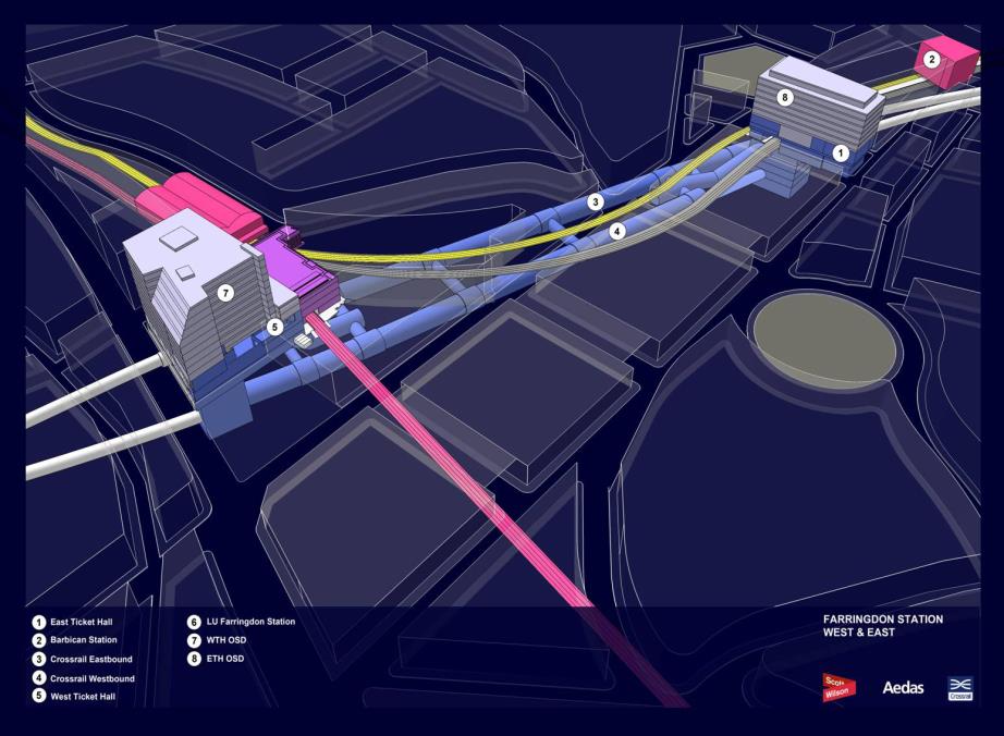
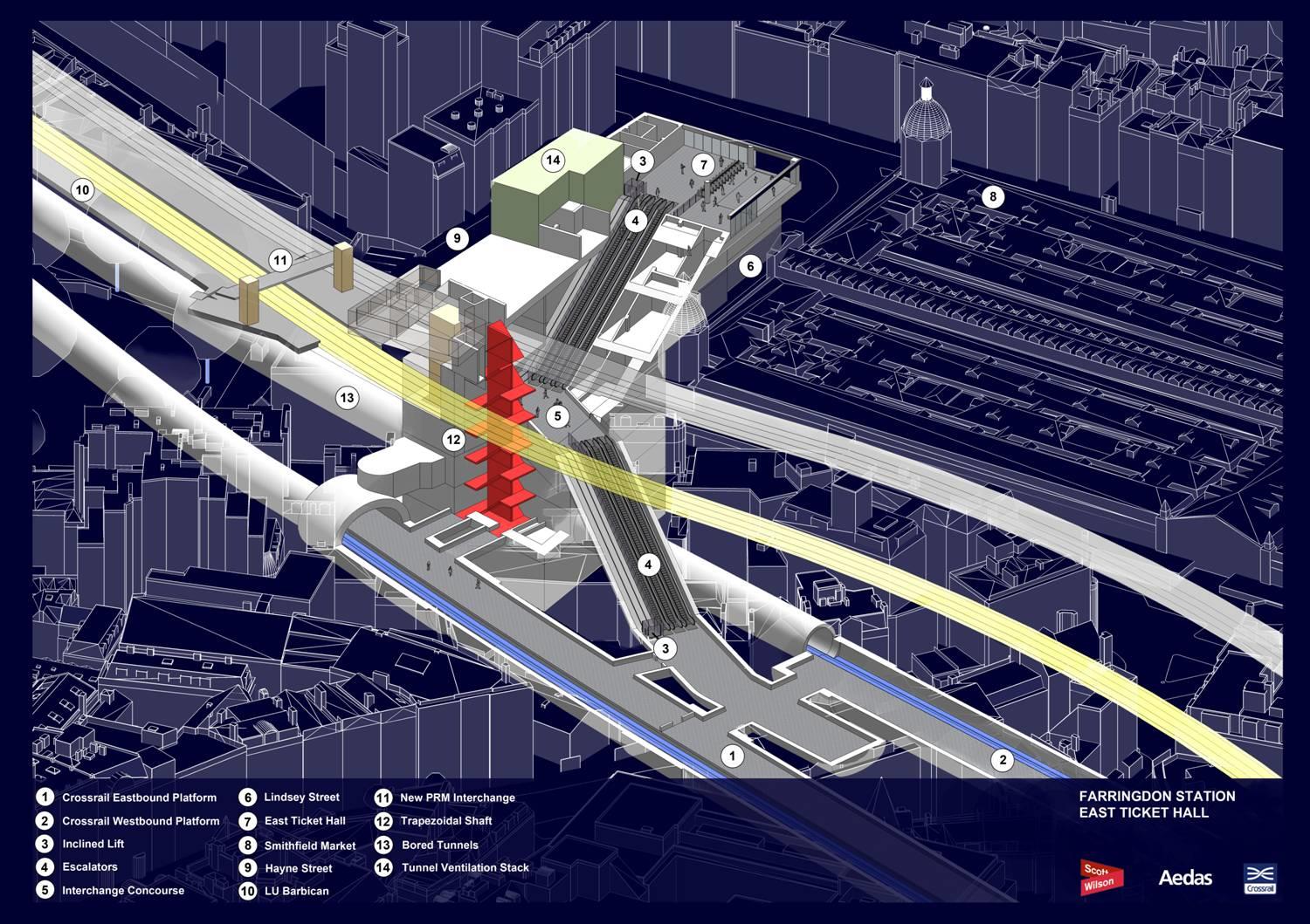
Figure 14 Farringdon – overall isometric view
Both sites were formerly occupied by buildings which have been demolished to allow construction of the ticket halls, shafts etc to take place. [Figures 15 & 16] At the WTH, there is a “collaborative” OSD (ie the developer is already established) while at the ETH there is a “non-collaborative” OSD where a scheme has been taken through to Planning Approval stage by the URS design team.
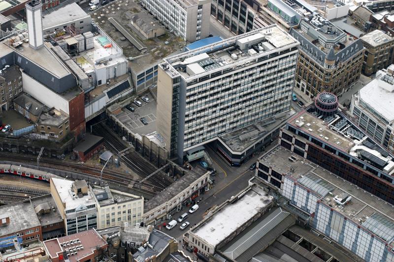
Figure 15 Farringdon western ticket hall – aerial view prior to demolition
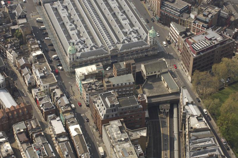
Figure 16 Farringdon eastern ticket hall – aerial view prior to demolition
Both ticket hall structures have been designed to accommodate vertical loads and stability loads from the proposed development, as well as making provision for ground level entrances, retail frontages, lift cores, connections to utilities etc.
One of the key buildings in the area is the Grade II* Smithfield Market, the east elevation of which is adjacent to the ETH site. At the WTH, the recently constructed Thameslink Ticket Hall has been designed to accommodate the future Crossrail station construction and to form an integrated Crossrail / Thameslink ticket hall and interchange.
Station Features
Platform Construction
As noted above, the ground at Farringdon is complex and heavily faulted, and the water-bearing gravels create extremely challenging conditions for the construction of the platform tunnels.
It was established early on in the design process that the platforms should be formed by SCL enlargements to lined pilot tunnels constructed using TBMs. [Figure 17] The pilot tunnel allows water-bearing channels to be depressurised via wells drilled out from the pilot tunnel, greatly reducing the risk of face collapse during the subsequent SCL enlargement works.
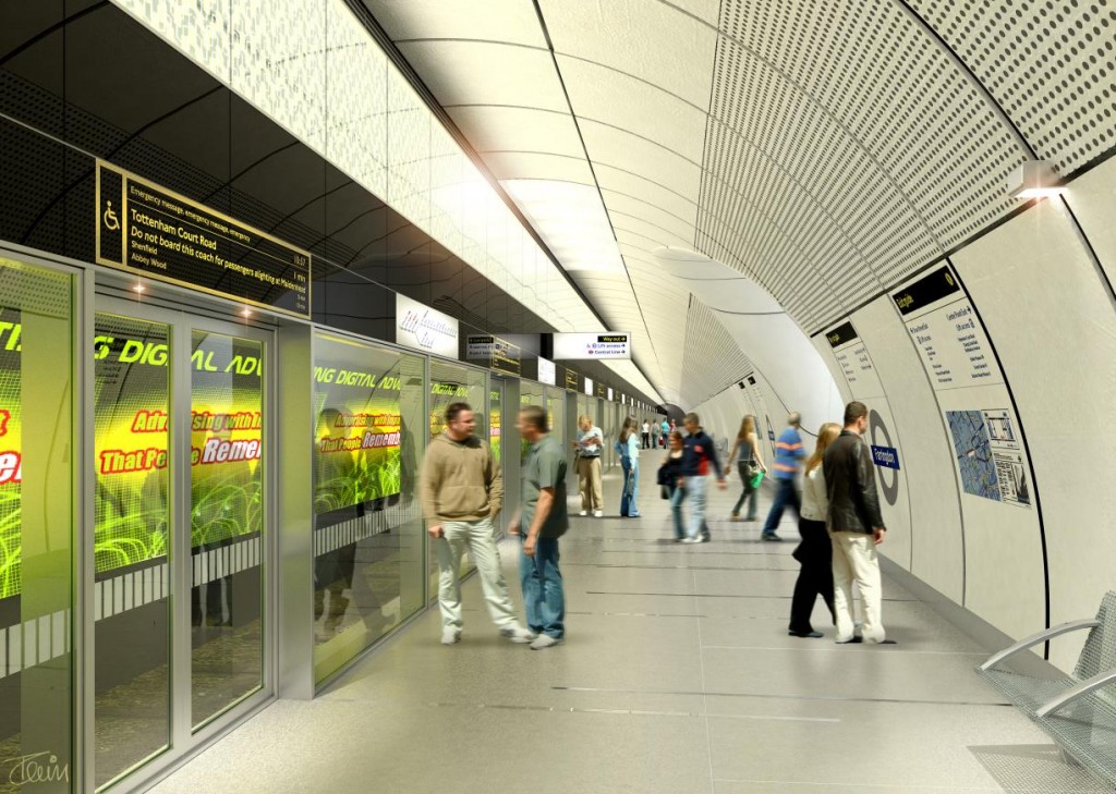
Figure 17 Typical mined station
Impact of tunnelling strategy
The impact of the tunnelling strategy at Farringdon is also very challenging as the station is the termination point for four TBMs.
The original strategy had been to terminate the X-Drive at the WTH site and the Y-Drive at the ETH, and to separately procure a smaller diameter TBM to construct the pilot tunnels. However, following a detailed study, it was decided to take the X-Drive through to the ETH and to use the standard diameter X-Drive tunnels as the pilot bores. Consequently the X-Drive passes through the WTH and on to the ETH. The ETH is now the termination point for all four TBMs.
Description of Ticket Hall Sites
Both ticket hall sites required the demolition of existing structures and both are bounded by roads, railways and structures, with original ground level typically 4 to 6m below road level.
The two sites are roughly rectangular and their overall dimensions are approximately:
- WTH: 65m x 48m
- ETH: 70m x 32m
The WTH site is bounded by:
- Farringdon Road to the west – Red Route
- Cowcross Street to the north – heavily-used / pedestrianised
- Recently demolished building to the south
- Newly constructed Thameslink ticket hall to the east (some loads from WTH are carried by the structure of the Thameslink Integrated ticket hall)
The ETH site is bounded by:
- LU lines to the north
- Barbican LU station to the north-east
- listed Smithfield Market to the west
- narrow street to the east and south
The suspended Moorgate spur of the Thameslink line passes through the site – to be reinstated on completion.
Form of Wall Construction / Sequence of Construction
The four shafts at Farringdon are irregular in shape, and are of different sizes and depths.
Access to the piling platforms, several metres below road level, is difficult. That and the size of the sites and their proximity to the rail infrastructure meant that diaphragm walled construction was considered inappropriate – leading to the choice of secant bored-pile wall construction.
WTH – 3No Shafts
Large rectangular shaft on the westbound tunnel (25m x 21m):
Provision for tunnel ventilation, service risers and emergency means of escape. It is necessary to excavate the shaft quickly to allow the westbound X-Drive TBM to pass through. The shaft is immediately adjacent to Farringdon Road, which contains major services – making it particularly important to limit ground movements. The need to excavate the shaft rapidly has dictated the use of bottom-up construction – but ground movements have been kept within specified limits by using stiff steel temporary frames at close centres.
Relatively shallow rectangular shaft (15m x 11m):
One level of temporary props and built bottom-up. Its primary function is to facilitate the construction of an inclined SCL escalator barrel.
Circular shaft on the eastbound tunnel (13m diameter)
Provides access for the construction of an SCL stub tunnel. The stub tunnel is required to enable the existing under-reamed piles from the now-demolished 1960’s building to be removed (these piles would otherwise have clashed with the passage of the incoming eastbound X-Drive TBM). It has circular concrete waling beams – subsequently cast integrally with the intermediary slabs. Rapid construction is required to allow for the construction of the stub tunnel prior to the arrival of the TBM. [Figures 18 & 19]
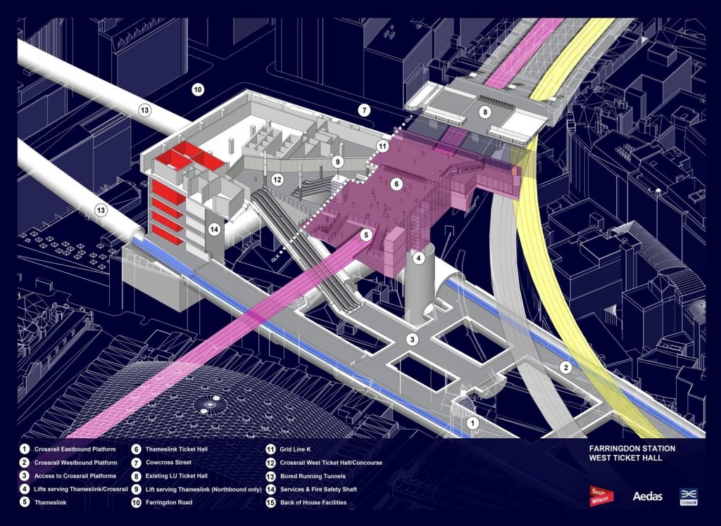
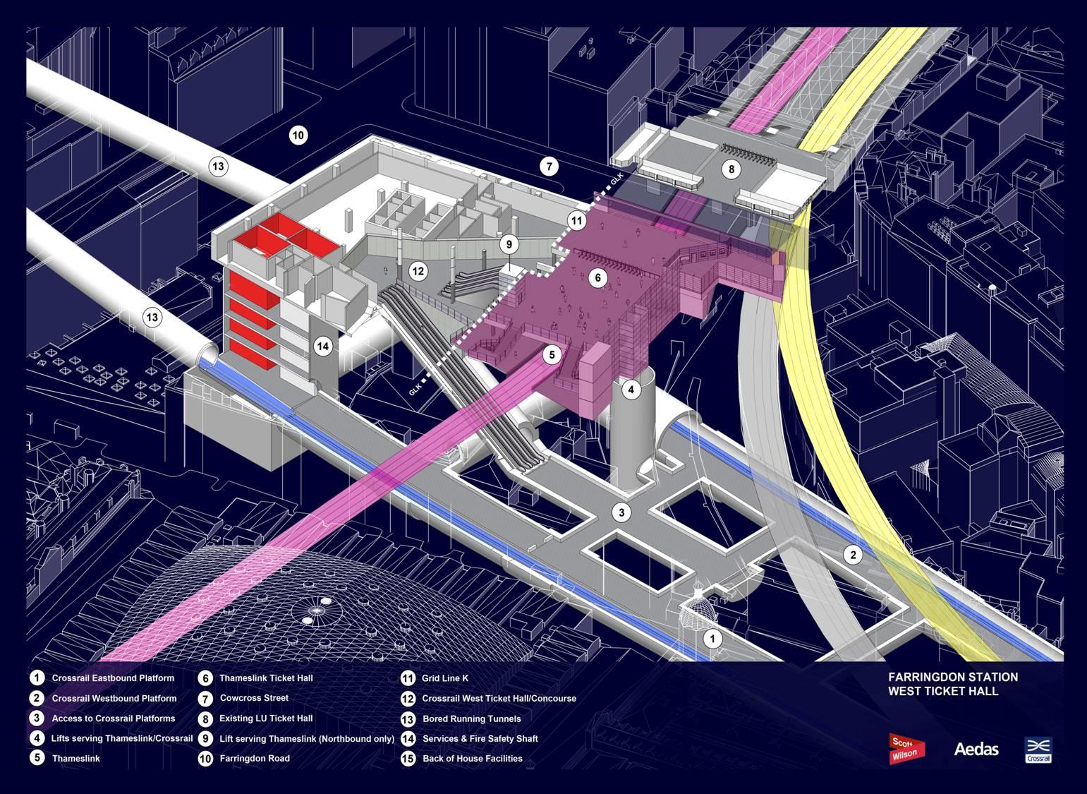
Figure 18 Farringdon western ticket hall isometric view
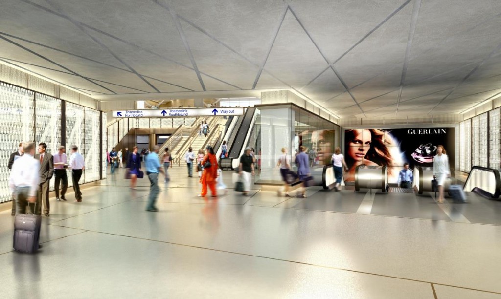
Figure 19 Farringdon integrated western ticket hall
ETH – 1No Shaft
Trapezoidal Shaft (30m x 25m)
A two-storey basement over the south half of the site houses M&E plant, while the north half of the site is occupied by a large deep trapezoidal shaft, which extends 35m below road level.
Its plan size is dictated by the need to accommodate tunnel ventilation, service risers, plant rooms, vertical transportation (two escalators and an inclined lift) and emergency means of escape. Space-proofing requirements have meant that the shaft extends to the site boundary on three sides.
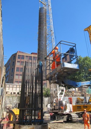
1.5m diameter secant bored piles are used in conjunction with top-down construction. Flat slabs prop the perimeter walls in the temporary and permanent condition – reducing wall displacements and hence controlling ground movements. These slabs are supported on the perimeter walls and internally on four steel columns, which are plunged into 1.5 m diameter piles. The steel plunge columns are subsequently cast into four 1.0 x 1.0m reinforced concrete columns, forming part of the permanent works. [Figure 20]
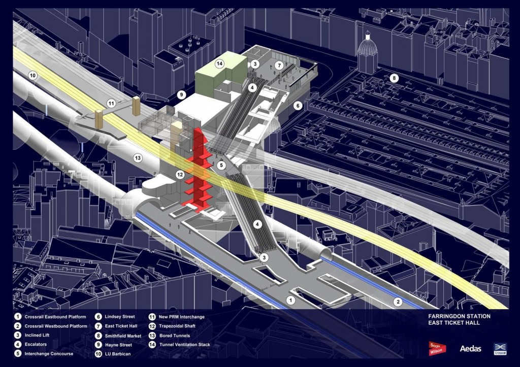
Figure 20 Farringdon eastern ticket hall isometric view
Integration with TBM Construction
The ETH trapezoidal shaft performs a vitally important role in terms of the tunnelling strategy as the termination point for four TBMs. Close collaboration was required with other consultants as well as with the two tunnelling contractors during the Optimal Contractor Involvement (OCI) phase.
X-Drive TBMs
- Large temporary voids are cast in the centre of the first three levels of permanent slab during the top-down construction. These voids allow the dismantled X-Drive TBM cutter heads to be craned out.
- A temporary SCL shaft is to be constructed within the trapezoidal shaft beneath the first three levels of slab.
- The westbound X-Drive TBM will bore through the west wall of the trapezoidal shaft and terminate within the temporary SCL shaft. The dismantled westbound X-Drive TBM cutter head will be taken out through the temporary voids.
- From the base of the temporary SCL shaft a temporary adit is to be mined out, passing through the north wall of the trapezoidal shaft to form a platform-sized reception chamber for the eastbound X-Drive, to the north of the trapezoidal shaft. The cutter head of this drive will also be removed through the ETH shaft.
- In both cases, the TBM train is taken back to the portal at Royal Oak, passing through Paddington Station.
Y-Drive TBMs
- The two Y-Drive TBMs arrive at the ETH approximately a year after the X-Drive, by which time the trapezoidal shaft will have been constructed
- The westbound Y-Drive TBM will therefore terminate in a platform sized reception chamber constructed immediately to the east of the trapezoidal shaft
- The eastbound Y-Drive TBM will terminate in the same platform-sized reception chamber as the eastbound X-Drive
- In both cases the whole of the TBM train, including cutter head, will return to the portal at Limmo, and will not be taken out through the ETH shaft. [Figure 21]
Figure 21 Farringdon eastern ticket hall temporary shaft and adits
The perimeter wall of the trapezoidal shaft is punctured by a total of six large openings:
- Two openings to accommodate the westbound running tunnel
- Three openings for tunnel ventilation and means of escape
- One opening for the inclined SCL escalator shaft.
Impact of OSDs
At both the WTH and ETH sites, the new ticket hall structures and their foundations are designed to support future oversite developments. Both ticket halls incorporate stub columns and a crash deck to allow construction at a future date. The Crossrail stations therefore do not form completed architectural entities but rely on the subsequent OSDs to re-establish the urban setting.
WTH OSD
The “collaborative” WTH OSD required close collaboration with the developer and their professional team to agree column & core locations. The developer’s consultants specified the vertical and horizontal loads to be carried by the ticket hall structure and foundations.
The presence of existing piles at the WTH from the demolished building and the area sterilised by the future tunnels imposes severe restrictions on the location of new piles. The vertical loads from the OSD are carried by a combination of the 2.1m diameter foundation piles and the three shafts. Some piles are sleeved to avoid load transfer from the piles to the tunnels and/or to reduce the impact of negative skin friction.
A deep raft slab, together with a series of transfer structures, transfer superstructure loads to the foundations.
ETH OSD
The “non-collaborative” ETH OSD has required the preparation of a design taken to planning approval stage. The OSD and ticket hall loads are carried by a combination of foundation piles and the raft slab of the trapezoidal shaft. [Figure 22]
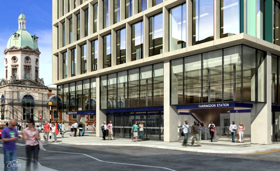
Figure 22 Farringdon eastern ticket hall hall image
DISCUSSION
While both stations:
- are on constrained inner city sites in highly developed areas of London,
- have links with major existing transportation infrastructure,
- are adjacent to historic listed structures,
- must integrate with the overall tunnelling strategy, and
- will provide a world-class railway,
it can be readily seen that the nature of the two sites has led to very different structural forms. The following table highlights some of the key differences:
Paddington Farringdon Entirely located beneath an existing road Located beneath existing buildings and major infrastructure Construction of ticket hall does not require demolition of major building structures (other than the taxi canopy) Construction of both ticket halls requires demolition of numerous existing buildings Single site Two sites (300m apart) Construction requires temporary closure of existing link road [Eastbourne Terrace] Construction adjacent to red route [Farringdon Road] – which cannot be closed. Adjacent to numerous roads which serve Smithfield Market Cut & cover platforms Mined SCL platforms with pilot TBM Relatively straightforward ground conditions. London Clay to depth Very complex, poor, faulted ground. Water bearing gravels Two TBMs pass through box, at an early stage in their journey. Station construction continues while tunnelling works progress eastward. Four TBMs terminate at site. Reception chambers required for dismantling and extracting cutter heads etc. Single Diaphragm-walled box – 1.0 & 1.2m thick panels.
Total length = 575m
Four separate secant bored-pile walled shafts – 1.2 & 1.5m diameter piles.
Total length = 400m (280 x 1.2m, 120 x 1.5m)
Top-down construction Mixture of top-down and bottom up construction. Temporary SCL shafts and adits to facilitate cutter head removal. Adjacent to Grade I listed building [Paddington Station & Macmillan House] Adjacent to Grade II* listed building [Smithfield Market] One local authority [City of Westminster] Three local authorities involved [Camden & Islington Boroughs and City of London] Adits linking to existing underground stations. Ground level connection to Paddington Mainline station. Shared concourse integrated with Thameslink. Indirect link to Circle, Hammersmith & City and Metropolitan LU Lines at Farringdon, and direct link to LU lines at Barbican. No OSD (other than potential for future OSD in the “bomb gap” in Macmillan House) Two OSDs (“collaborative” and “non-collaborative”). Construction of associated crash decks and the provision of additional foundation and substructure capacity. Ground movements are a function of wall deflection and these were controlled by a combination of the sequence of excavation and the stiffnesses of perimeter walls and of the horizontal props. Diaphragm walling is inherently stiffer than a secant bored pile wall of same overall thickness. This greater stiffness leads to smaller wall deflections and hence lower ground movements during excavation. However the size of plant required to construct the panels and to install the reinforcement can be very large. This, combined with need for bentonite storage, means that diaphragm walling is better suited to large sites with good access, and to wall layouts that are reasonably rectilinear.
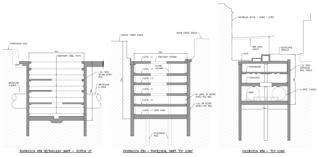
Figure 23 Paddington and Farringdon – comparison of shaft construction
In assessing the most appropriate form of wall construction at these two stations, it was considered that diaphragm walling techniques were best suited to the single regular box at Paddington. At Farringdon, however, the need to construct very deep, irregularly shaped shafts on sites with difficult access, close to rail infrastructure, meant that a secant bored pile solution was more appropriate. Top down construction was used except where ground movements were not critical or where programme requirements dictated the need to complete shaft excavation at the earliest opportunity (as is the case for the rectangular shaft at the WTH). In terms of the structural solutions, diagrams have been prepared to give a direct visual comparison of the resulting designs for the two major shafts at Farringdon Station and the main box at Paddington Station. [Figure 23] The key features of these three shafts / boxes are summarised in the table below:
Shaft / Box Dims: Depth x Width Construction Sequence Wall type Dimensions
Moment of Inertia
Prop type Farringdon WTH Rectangular Shaft 28m x 26m Bottom-up Secant bored-pile 1200mm Φ @ 1550 c/c
0.066 m4/m
Temporary steel props Farringdon ETH Trapezoidal Shaft 37m x 25m Top-down Secant bored-pile 1500mm Φ @ 1950 c/c
0.127 m4/m
Flat slab Paddington Main Box 25m x 25m Top-down Diaphragm wall 1200mm panels
0.144 m4/m
Flat slab (with coffers) CONCLUSION
Both stations share key issues. Both have to meet similar performance requirements, control ground movements and integrate with the tunnelling operations. However the particular constraints of the two sites have resulted in very different structural forms and different construction methodologies.
The underlying design philosophy and the key drivers of safety, economy and constructability remain the same [Figures 24 & 25], and the collaboration with other consultants, third party stakeholders and the contractor to develop these solutions to resolve design issues is vitally important for both stations.

Figure 24 Farringdon western ticket hall site progress photograph Sept 2012
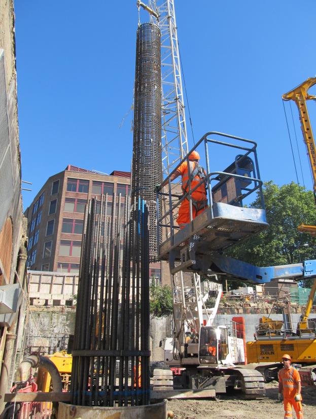
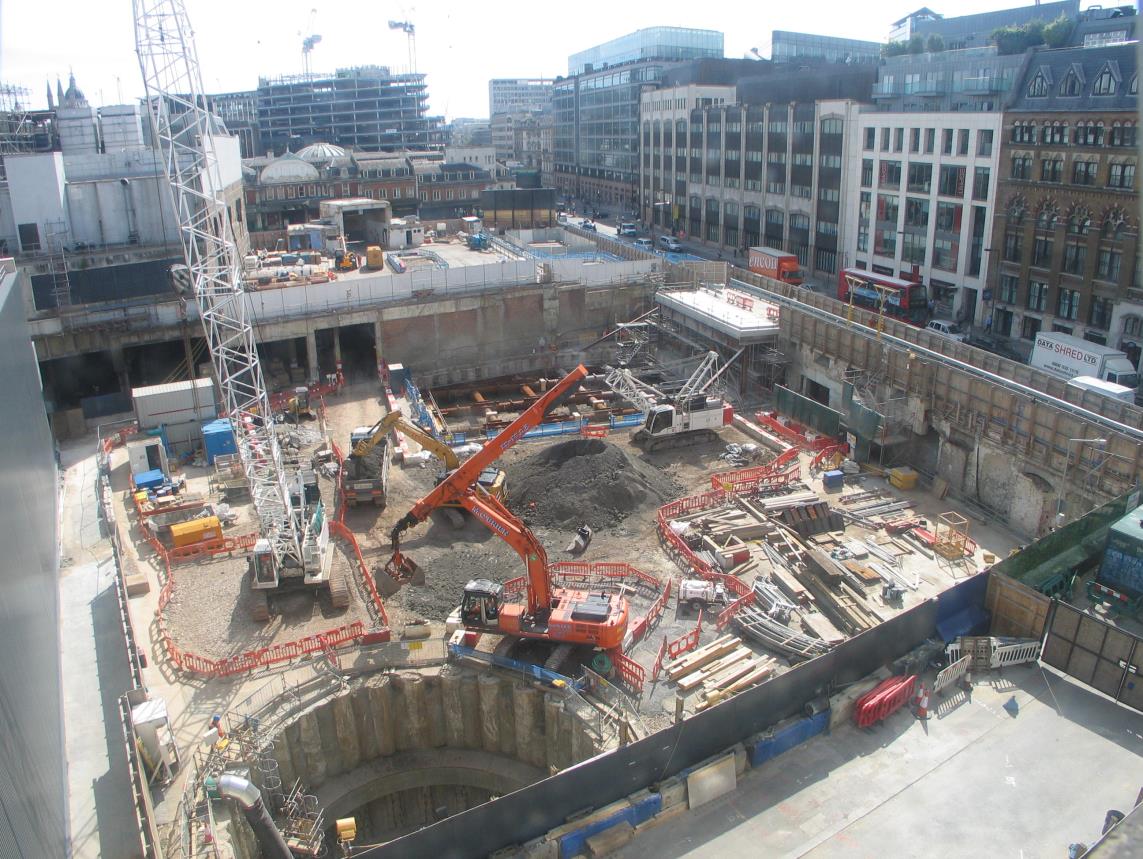
Figure 25 Farringdon eastern ticket hall site progress photograph Sept 2012
-
Authors

James Paterson MA MSc DIC CEng FICE MIStructE CPEng FIEAust - URS
Lead Civil and Structural Engineer for Farringdon Station, URS
Mark Raiss MA MSc DIC PhD CEng FICE FIStructE FCS - URS
Crossrail Programme Director, URS