Diaphragm Wall Construction at Woolwich Arsenal Station Box
Document
type: Technical Paper
Author:
Mark Pennington
Publication
Date: 10/11/2015
-
Read the full document
1.0 Introduction
The Woolwich Arsenal Station box is being constructed for Crossrail by Berkeley Homes. The station will provide access to a significant new development being constructed by Berkeley Homes at the Western End of the Crossrail route. The location of the site in relation to the crossrail scheme is shown in Figure 1.
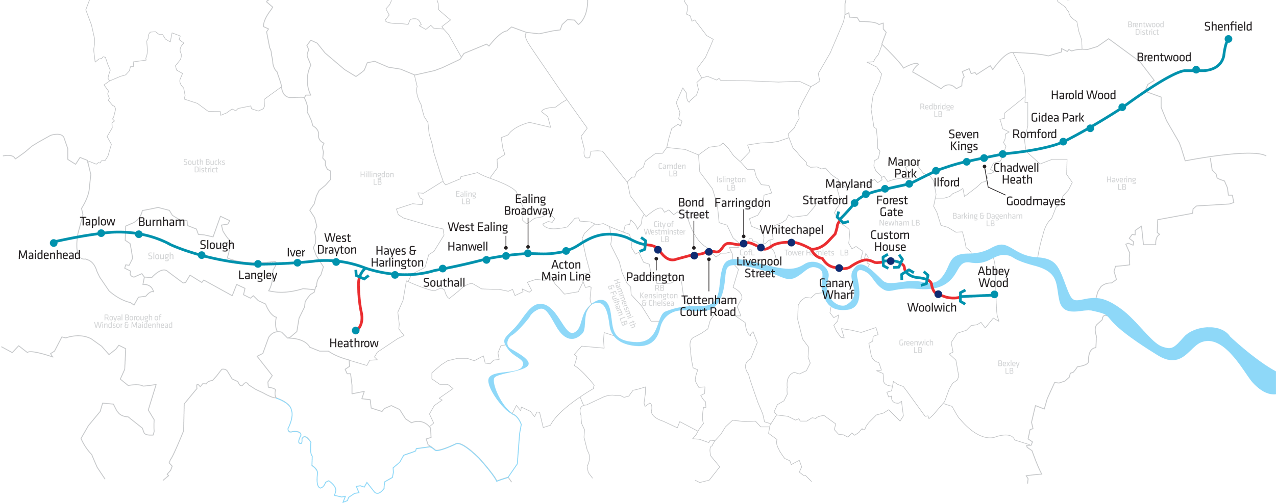
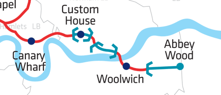
Figure 1 : Site location
This site is one of the few sections of the Crossrail structure that are south of the river Thames. It’s location is at the eastern end of the London Basin meaning the ground conditions are different too much of the tunnelled sections of Crossrail where significant depths of London Clay are present.
The piling and diaphragm walling works for the Station Box was constructed by Balfour Beatty Ground Engineering directly for Berkeley homes. The basic requirement was to provide a box approximately 260m long 23m to 29m wide and 12m to 13m deep to allow the tunnel boring machine for the South Western drive to pass through. For both tunnel drives, the TBM would enter the box from the Eastern end and then exit towards West. When the TBM had passed through for both of the tunnel drives the station could be constructed within the box.
2.0 Scope of the Piling Work and Method of Construction
2.1 Diaphragm Wall
The piling scope comprised the construction of 500 linear metres of 1000mm wide diaphragm wall. The wall was constructed out of 88 different panels which were up to 7.1m in length. The diaphragm wall panels were not particularly deep at 24.5m. This depth was adequate to allow the 12 to 14 metre excavation. The diaphragm wall provided the support to allow the station box to be excavated, was propped at the top and the basement slab level and did not need to provide a water cut-off in the temporary condition to allow the excavation as a temporary de-watering system was employed. This reduced the water pressure around the box to allow excavation of the box in a dry condition.
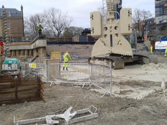
The diaphragm wall was constructed using Kelly Bar Grabs as shown in Photographs 1 and 2. These grabs excavate the panels in a standard manner (in bites), bringing the excavated material to the surface to be stock piled and then disposed off site. During excavation the panel needed to be supported by site mixed bentonite support fluid to avoid collapse.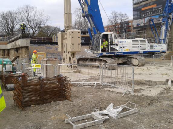

Photograph 1 and 2 : Diaphragm Wall Construction
At the ends of the box the diaphragm wall panels were constructed with fibre glass reinforcement cages to allow the TBM to easily excavate through the panels.
2.2 Bearing and Tension Piles
In addition to the diaphragm wall there were a number of piles both inside and outside the box:
The piles inside the box acted as tension piles within the box to prevent the box from lifting due to water pressure uplift. These comprised 51 piles, 1500mm to 1800mm in diameter with a bored length
of 32m to 46m. These piles were constructed from ground level with the concrete cut-off level at 12m to 14m below the platform at the mass excavation level. These piles were constructed using standard large diameter rotary piling and required the use of bentonite support fluid during construction.The piles outside the box were installed as foundation piles to support the superstructure associated with the station and the Berkeley Homes development. These comprised 418 piles, 750mm in diameter with depths of 16.5 to 33.5m. These piles were constructed using continuous flight auger piling. This meant that the piles could be constructed without the use of support fluid.
2.3 Temporary Works Piling
In addition to the permanent works piling there was a significant amount of temporary works piling required to enable construction. This included a slurry wall which allowed the box to be excavated in two halves, lean mix walls at the end of the box to allow the TBM’s to enter the box and stop for some time without water ingress or getting stuck and grouting to allow the diaphragm wall to be constructed – described in sections 4, 5 and 6.
Figure 2 shows diagrammatically the scope of works.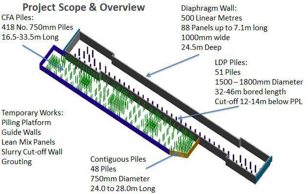
Figure 2 : Scope of Works
3.0 Ground Conditions
The ground conditions at the site are not typical of the standard London Basin strata that exists for much of the underground section of Crossrail.
The site comprises approximately 1.0m of made ground, overlying 2.5m of terrace gravel, overlying 11m of Thanet Sand, overlying a 1.0m band of Bull Head beds on top of Chalk (Figure 3). This strata did not provide any obvious water cut-off hence the requirement for temporary de-watering. All of the
strata is permeable and the need for support fluid to support any open excavation during piling or diaphragm wall construction was essential.Particular attention was given to the details of the Bullhead bed layer which was considered critical to the diaphragm wall construction for reasons discussed in Section 5.0 below. The site investigations had not particularly targeted this layer for investigation and so the information was not as complete as it should have been. In particular there was no information on the permeability of the layer. The Bullhead Bed is a distinctive unit that is commonly present at the base of the Thanet Formation and usually comprises small well-rounded flint gravel ranging in size and shape to cobbles and fine boulder of unworn nodular flint, within a dark greenish grey or black glauconitic sandy clay or clayey sand matrix. The flint nodules (the “bullheads”), which can be up to 0.3m in diameter, are characteristically green-coated. Fossils derived from the chalk occur in places. The unit is generally 0.5 to 1.0m thick.
The ground water levels from Geological information are stated to vary from 5m to 10m below ground level. This confirmed during pile construction on site. As discussed a de-watering system was employed prior to excavation of the box to locally draw the water table to below the excavation level.
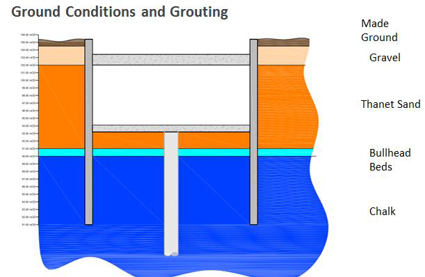
Figure 3 : Typical Ground Conditions
4.0 Existing Knowledge of the Area
The Balfour Beatty Ground Engineering team had recent experience of constructing a diaphragm wall approximately 200m to the South of this site. This was part of the TBM reception chamber for the Docklands Light Railway Extension – City Airport to Woolwich Arsenal. The relative location of the two projects is shown on Figure 4. During construction of this diaphragm wall, a significant amount of the bentonite support fluid was suddenly and unexpectedly lost when the diaphragm wall excavation reached the Bull Head beds. The support fluid apparently flowed into the Bull Head bed strata leaving an open and potentially unstable diaphragm wall trench above this level. It was not possible to recharge the excavation with more support fluid as this ran away.
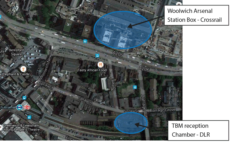
Figure 4 : Relative Position of DLR Diaphragm Wall and Crossrail Diaphragm Wall
This diaphragm wall panel was backfilled and a grouting operation quickly planned to seal the bull head beds either side of the diaphragm wall. Grouting was carried out using a continuous flight auger (CFA) piling ring casting concrete through the level of the Bull head beds and then back screwing out above this. This grouting was carried out using a 900mm diameter auger with piles at approximate 2000mm spacing c/c. This grouting operation proved successful and the diaphragm wall could be constructed.
There was no specific information from the site investigation carried out at the Woolwich Arsenal site to suggest that bentonite may be lost during construction. However, the bull head beds descriptions were very similar to those on the Docklands Light Railway Site and so it was considered prudent to carry out some grouting works of these beds.
5.0 Proposed Grouting Solution
The proposed grouting solution at the start of the project was to drill 114mm cased holes at 2.0m centres each side of the guidewall constructed for the diaphragm wall. The grout holes on each side of the wall would be staggered by 1.0m. This meant the grout holes would be spaced 2.0m in line with the diaphragm wall and 2.6m perpendicular to the wall. Grout would be pumped into the holes over the depth of the Bull Head Beds only and the holes would be backfilled above this with arisings. The pressure and the grout take would be measured and recorded during grouting. This proposal would utilise minimal grout but provide a seal. The general arrangement of the grouting proposal is set out in Figure 5.
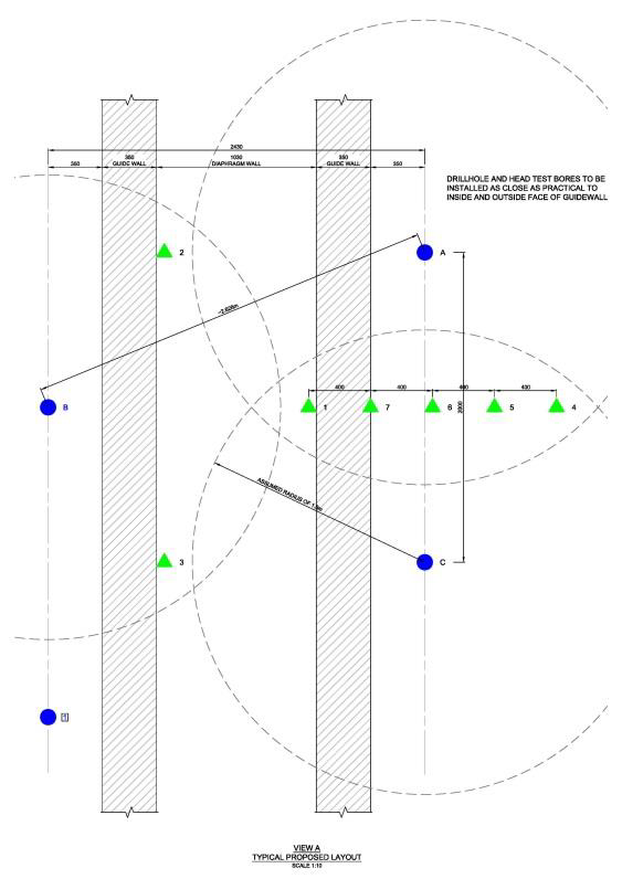
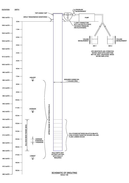
Figure 5 : Plan and Section through proposed Grouting
The assumption was that grout would extend 1.5m into the bull head beds from each grout hole location. The overlap of the grout positions would provide a barrier to prevent flow of the Bentonite support fluid into the Bull Head beds. In order to check the grouting was successful, a number of falling head permeability tests were proposed in between the grout holes.
No grouting was planned for the large diameter piles cast using support fluid within the station box.
6.0 Construction and Final Solution
During detailed planning of the diaphragm wall construction and grouting operation it was assessed that constructing the grouting operation using a 350mm diameter CFA auger would provide significant programme advantage providing cost savings in excess of the additional grout required. The 350mm diameter CFA piles were proposed at the same locations as the mini piled solution. As at DLR, grout was installed only through the layer of the bull head beads with the auger then back screwed out above this.
The CFA auger was extended through the Bull Head beds into the chalk in the usual manner. A pre-mixed grout with a 28 Day strength of 2 to 4 N/mm2 was then pumped through the hollow stem of the auger. The auger was then lifted in the usual manner to the top level of the Bull Head beds. The auger was then stopped and up to 2.0m3 of additional grout pumped into the holes.
Diaphragm Wall construction was programmed to commence in the South Western corner of the site. The grouting and falling head permeability testing was successfully carried out in the area and the first panel excavated under the bentonite support fluid. When the panel excavation reached the bull head bed layer, the support fluid suddenly dropped within the panel to the level of the Bull Head beds. It was clear that the grouting operation had not proved successful.
A revised grouting proposal was developed, using the same grout mix but closing up the spacings of the grouting holes. This comprised a full grout curtain around the affected panel (see Figure 6), tertiary grout holes in between the primary proposed holes and grouting in between the guide walls (see Figure 7).
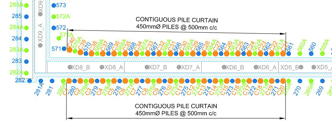
Figure 6 – Grout curtain around affected panel
The revised solution meant that primary and tertiary CFA grouting solution provided grout holes 1.0m centres along the line of the wall either side of the guidewall. The inclusion of grout holes on the line of the diaphragm wall meant that potential bentonite flow parallel to the line of the diaphragm wall also also cut-off.
Additional falling head permeability tests were carried out within each of the panels prior to construction to ensure the grouting operation had worked.

Figure 7 – Revised Grouting proposal
The revised grouting operation proved successful and allowed the diaphragm wall construction to proceed. As the diaphragm wall construction progressed from the western side of the box to the eastern side the grout take from the CFA piling was noted to reduce significantly. Maintaining the grouting in the line of the wall and carrying out falling head permeability tests it was possible to reduce the grouting along the line of the wall back to the primary locations only at a 2.0m spacing. The primary holes were used on their own where the grout take on these holes was less than 2.0m3.
No grouting was planned or used for the piles constructed under bentonite. These piles were constructed in the usual manner. The issue of bentonite loss during construction was for the diaphragm wall construction only. This must have meant is was either a function of the construction technique or the exposed area of bull head beds – or possibly a combination of the two.
7.0 Conclusion
It was clear from construction at the Woolwich Arsenal site that previous knowledge of the ground and in particular how the use of bentonite support fluid was influenced be the presence of the Bullhead Bed, was key in developing a constructible solution. Even with this previous knowledge problems were encountered during the construction phase. The ground and how this affected the construction varied across the length of the site.
This highlights a number of key points:
- Any previous experience of similar construction in similar ground is key.
- Good initial site investigation providing the correct information for the proposed construction can save significant time and cost during construction.
- In difficult ground conditions time and cost of temporary works to allow construction to proceed may be considerable.
- Particular care and thought needs to be taken when relying on support fluid for pile or wall construction
-
Authors