Digital Railway – Telecoms Technologies for the Elizabeth Line – An Infrastructure Manager’s Perspective
Document
type: Technical Paper
Author:
Philip Bartholomew MEng MSc CEng MIET MIRSE, Archana Radhakrishnan MSc MIET
Publication
Date: 02/12/2021
-
Read the full document
Introduction
It’s difficult to capture in a short technical article, the complex, intricate, inter-dependent, sometimes painful, but ultimately successful path of the technical development journey of the past fifteen years. In 2007, the first seeds of ideas of how Crossrail, ultimately to be branded the Elizabeth Line, would employ digital technologies in the communications arena were being formed. The original concept sought to take the best of technologies available in the day and then project forward approximately 10 years to predict how these would develop and new technologies emerge in the traditionally conservative railway industry.
It’s now 2021 and the predicted technologies of tomorrow have become the benchmark, expected technologies of today with a greater prediction of technological development in the next ten years. The Elizabeth Line has now entered the ‘Trial Running’ phase with much of the Digital capability in service for running the Central Operating Section (COS) routeway and stations capability progressively being added as the year unfolds. The vision has progressively morphed into reality and the telecoms technologies chosen installed, extensively tested, commissioned and brought into service.
So how does this look from an Infrastructure Manager’s perspective?
From 2007, the Systems and Rolling Stock team developed the concept design required to obtain approval for the hybrid bill along with the ‘Digital Vision’ of how the technology used would realise a new railway for London, offering a step change in technology application. ‘Predict and Prevent’ was the guiding principle to describe how the railway would be monitored to allow engineers to anticipate where problems had begun to occur before they became service affecting. Having successfully seen the Hybrid Bill through parliament and with the railway into full construction, the Rail for London Infrastructure (RFLI) team was setup, with the purpose of accepting, operating and maintaining the assets of the Elizabeth Line. Our role with respect to the assets through the design and build stages of the project was threefold:
- Oversee, review and accept the design of assets delivered by the Crossrail Project.
- Monitor the construction to ensure that the needs of Operations and Maintenance were met.
- Ensure that the testing was undertaken accurately, thoroughly, competently and with enough rigour to ensure that the integrated systems would be safe, operable, maintainable, and perform to the required level for a world class new railway for London.
One of the first things to hit me when starting on this journey was the sheer complexity of the new Elizabeth Line. With four distinct geographical sections (Great Western, Central Operating Section, Great Eastern and SouthEast Spur) each with its own combination of stations, Operators, IMs and stakeholders, all systems, and especially the Communications and Control (Telecoms) systems had to be extremely flexible and adaptable to cater for the differing requirements of each area and parties involved.
The Elizabeth Line has been described as a ‘Short and Wide’ railway, meaning that it packs a lot of functionality into a relatively small geographical area, compared to, for example, HS2 which is ‘long and thin’. To give an idea of the scale of the complexity that these dimensions bring, here are some of the numbers involved.
- More than 60,000 Comms and Control Assets
- More than 40,000 SCADA Points
- 6 Different radio systems across 12 different frequency bands
- More than 100 railway Control Points across 41 stations
- Over 250KM of Optical Fibre Cable
- A vast quantity of Copper Cable
All of this over 96KM of track, with 42KM of it new!
Having all of these assets and systems delivered new is, in some ways, an Infrastructure Manager’s dream! When you have experienced the real challenges of old assets, with limited spares availability and poor reliability, the thought of ‘all new’ is a welcome change. On the other hand, the need to work through the early days of the assets’ operation, ‘bedding in’ and dealing with ‘early life’ failures and difficulties, while in parallel writing the standards, procedures and processes necessary to achieve opening has been a massive challenge. Coupled with this, the development of the design, build and testing over 10 years or more has meant that obsolescence has become a problem far sooner into Operation than we may have expected for a typical rail project.
So in this paper, the aim is to present the Infrastructure Manager’s view of the implementation of the many telecoms technologies across the route. A factual coverage of the function and particular implementation of the systems will be presented along with an evaluation of the degree to which the digital vision has been realised.
Route Control Centre
At the heart of the Elizabeth Line operation is the Route Control Centre (RCC) at Romford which acts as the controlling and monitoring hub of the network. Naturally the Communications and Control systems have a focus at the RCC as many of the staff who operate these systems and monitor their health are based at this location. A large climate-controlled set of equipment rooms at the site provides a suitable environment for much of the headend equipment and provides a suitable landing point for the interface to the operating floor.
Central Management System (CMS) and Station Management System (SMS) – SCADA
The CMS and SMS SCADA systems, as their names suggests provide a supervisory control and data acquisition system both across the entire Elizabeth Line route and at individual stations respectively. The core of the system is a set of Siemens Railcom Manager (RCM) servers and workstations coupled with a significant quantity of Siemens fastflex RTUs distributed at stations, shafts, portals and other routeway sites. Together these provide a control and monitoring platform for the many thousands of field assets distributed along the route including all communications, traction and domestic power, mechanical, electrical, public health and security assets. Rather than a single system, this can be thought of as a ‘system of systems’ which allows the operators at the various sites to have ‘eyes and ears’ along the route and effectively operate the railway from an integrated headend. This provides an excellent way to consolidate monitoring and control decision making from a small number of discrete locations and individuals. One of the challenges this brings, however, is the complexity of the systems required to bring this technology together to support the route configuration.
This system ‘brain’ which controls and monitors the many thousands of field-based assets, like all assets forming part of the Elizabeth Line, has been designed to be: –
- Safe
- Reliable
- Maintainable
- Perform to the required standard
These four objectives are common to all assets deployed on the Elizabeth Line, but the CMS and SMS are systems which allow both Operators and Maintainers to see just how well these objectives are being met both in the short and long terms for all systems monitored. This is communicated through a number of distributed workstations and reports provided from the system data. At the time of writing the capabilities of the reporting function and the use of these in monitoring, predicting and improving performance are still being developed. However, it is believed that the capabilities offered will deliver a step change in railway asset monitoring and operation allowing a true ‘predict and prevent’ philosophy to be applied to the railway. The central goal of any asset management approach is to ensure that all assets play their part in achieving effective railway service for passengers to the required standard. The CMS and SMS systems greatly improve the capability of the Operator and Maintainer to achieve this goal in daily service.
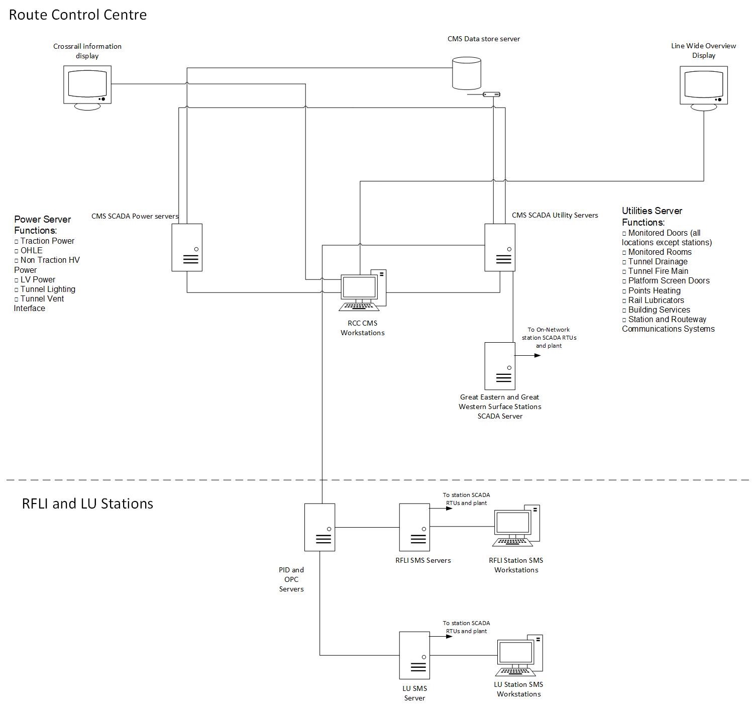
Figure 1. CMS and SMS System Schematic – The ‘Brain’
Crossrail Data Network
The fact that assets are distributed all along the Elizabeth Line route in just about every Operational location and need to be tied together into a common communication network, means that a common data ‘backbone’ is required. This is provided by the Crossrail Data Network (CDN) consisting of a large set of switches, routers, firewalls, modems and associated equipment plus a large quantity of optical fibre and copper cable, routed through all areas of the Elizabeth Line locations. The network is highly resilient, providing diversity at many levels of the architecture, ensuring that the system can continue to transport data in the event of one and, in some instances, more than one failure. The network provides a dual 10Gbit/s set of resilient rings distributed around the Elizabeth Line with 1Gbit/s and 100Mbit/s connections employed where capacity needs allow.
The CDN was one of the first of the Communications networks to be installed and tested as it forms the layer on which all other systems are built. It has proved to be highly reliable in its first years of operation, suffering very few failures. The key central assets of the network are installed into climate-controlled equipment rooms to provide the best possible dependability with those areas which are hard to reach or suffer with, for example, high electrical interference, supplied with specially ruggedised variants.
One of the great advantages of the CDN is its ability to interface with so many different manufacturers’ systems to provide data transport and to be intelligent enough to understand and optimise for its own state of health. It acts as the ‘data veins and arteries’ of the Elizabeth Line, providing something akin to an industrial grade broadband service.
As you would expect from an intelligent data network, the CDN reports its health status into the headend, raising critical alarms on the CMS and providing asset performance and monitoring data to maintainers through the use of a proprietary software and analytics package.
Telephony
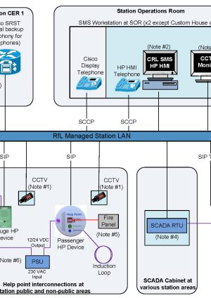
At the heart of any operating railway is the ability to communicate with persons remotely. With the rise of mobile and radio-based communications, a reasonable percentage of this communications has moved to systems offering this mobile capability, including GSM-R and other radio technologies. However, a fixed line telephony system still, maybe surprisingly, is still at the heart of person to person and person to group communications. A new telephony system has been provided for the COS based on Voice over Internet Protocol (VOIP). The system comprises telephone instruments, telephony servers, voice routers and gateways, voice recorders, help point servers and help point end user devices. These provide a system which connects every significant location along the COS and allows conventional push button full number routing, short code dialling and direct line communications to signallers, electrical control, stations operations rooms, platforms, tunnels, lifts, escalators and all equipment rooms.
The Route Control Centre staff naturally have a large need for voice communications, hence the telephone units employed at this location and the Backup Control Facility (BUCF) are a special type of unit offering enhanced facilities and a large number of pre-programmed keys to enable rapid selection of end calling points.
The telephony systems reports its health status and allows configuration changes to be made at the RCC using a similar technology platform to that used for the CDN.

Figure 2. Typical Station Telephony Schematic – The ‘Ears’ and ‘Mouth’
Radio Systems
Elizabeth Line radio systems provide the main means of mobile voice communications within the COS and beyond. Within the COS, a Private Mobile Radio (PMR) system using Radio Frequency over Fibre (RFOF) technology provides Global System for Mobile Communications – Railway (GSM-R), Airwave, London Fire and Emergency Planning Authority Channel 5 (LFEPA Ch5) and LU Connect services.
The radio systems report their health and performance to a dedicated platform which provides integration with the CMS for overview monitoring and reporting of critical alarms.
RFOF
PMR makes use of RFoF technology to transmit all radio signals from the base stations to the tunnels, cross passages, stations and supporting buildings. The RFoF system consists of two main components, an Optical Master Unit (OMU) and multiple Fibre Repeaters / Remote Units (RU). The OMU takes RF signals from the base stations and converts to optical signals to distribute remotely to fibre repeaters through the tunnel fibre optic cables. The RUs are geographically dispersed and positioned in suitable locations to provide comprehensive coverage. The RUs convert the optical signal back to RF for distribution through the radiating cables in the tunnels and in buildings using a coaxial Distributed Antenna System (DAS). As optical fibre cables are used to carry the radio signals, they can travel long distances without the need for powered RF amplifiers.
The RFoF system is self-monitoring allowing the status of OMUs and RUs to be monitored. In the event of an asset or optical fibre link failure, the affected OMU raises an alarm on the CMS.
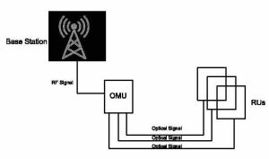
Figure 3. RFoF System Schematic
GSM-R
GSM-R is the National Standard radio system which provides secure and reliable communication between the train driver and signaller. The GSM-R system used in Elizabeth Line COS is an extension of the Network Rail GSM-R National Network and the coverage is provided by means of new GSM-R Base Transceiver Stations (BTS) located across the COS. Other than providing secure voice communications between train driver and signaller, GSM-R in Elizabeth Line COS is also used for providing radio services for:
- Railway maintenance staff
- Station staff radio at RFLI Managed Stations
The GSM-R radio coverage in the west and east surface sections is provided by the Network Rail system for those routes.
The GSM-R system in the COS is more resilient than the Network Rail GSM-R system as there are multiple base stations across the central section. The Central Section is divided into 5 sectors with each sector being fed from a single primary BTS/transceiver. A secondary BTS has been located within sectors 2 – 5 but in a different geographical location for resilience purpose. The RUs are connected to two separate base stations for resilience, providing continuous coverage in the event of failure with minimal disruption to service.
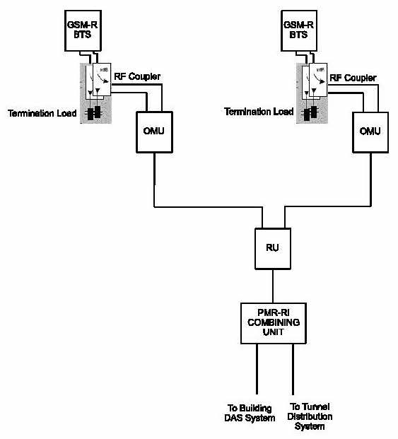
Figure 4. GSM-R System Schematic
The GSM-R base stations are monitored directly by NR National Network Telecoms Engineering Centre (TEC) through the 2Mbit/s link to each base station.
Airwave
The Airwave Crossrail (ACRL) system is a TETRA based service providing the Emergency Services with mobile communications and is designed to support the National Airwave TETRA service provided across the UK. Coverage within the COS is provided by Airwave Base Stations or the existing Airwave London Underground (ALU) systems from LU Connect.
There are 3 sectors in the Central Section with each sector being fed from a single BTS. There are no standby BTS provided for Airwave, different from the GSM-R system, due to the systems’ relative criticalities. The Airwave BTSs in the COS are connected to co-located OMUs and the signals presented to the OMUs through the RFoF infrastructure to RUs. RUs are located throughout the COS. The output of each RU is connected to the PMR-RI for the distribution of RF signals to the tunnels and DAS in the buildings.
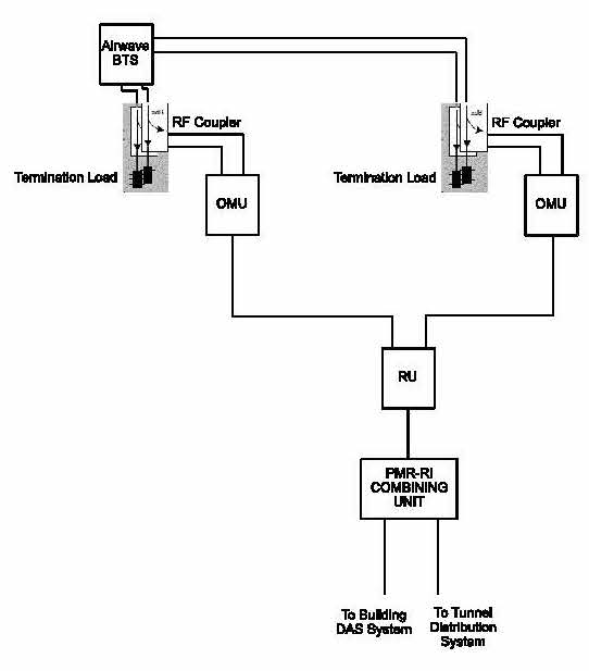
Figure 5. Airwave System Schematic
Resilience is provided to the ACRL radio system by connecting dual fibres on each RU to two separate OMUs. In the unlikely event an OMU fails, the affected RUs switch to the secondary path back to the standby OMU thus providing continuous coverage. Unlike the GSM-R system both primary and secondary OMUs are connected to the same BTS. Hence, in the event of a BTS failure the entire sector will be without coverage until the BTS is repaired. However, the BTS is a highly available unit.
LFEPA
The LFEPA Channel 5 Radio System is an analogue communication system that provides radio coverage for the London Fire Brigade. Coverage within the COS is provided either by new base stations or by enhancing existing LU LFEPA signals in LU interchange stations.
In some areas, new LFEPA BTSs are connected to co-located OMUs and fed via Rus are for Airwave and GSM-R. In some locations, the radiating infrastructure is directly fed. At LU Interchange Stations, it was originally intended that a channelized off-air repeater be used instead of a BTS for simplicity. However, this setup did not provide the required quality and reliability, hence the system was changed to a directly fed arrangement.
LFEPA resilience is provided by connecting dual fibres between OMU and RU. Unlike GSM-R and Airwave no secondary OMUs or base stations are deployed. Therefore, the loss of a base station, OMU or RU would result in a loss of that section of tunnel or station.
This lack of full resilience for a system which the emergency services rely on for search and rescue operations has meant that RFLI have had to pay careful attention to maintaining an available stock of spare BTS, OMU and RU, so that in the event of failure, a simple swap out of equipment can be performed to achieve the required 2-hour Mean Active Repair Time (MART).
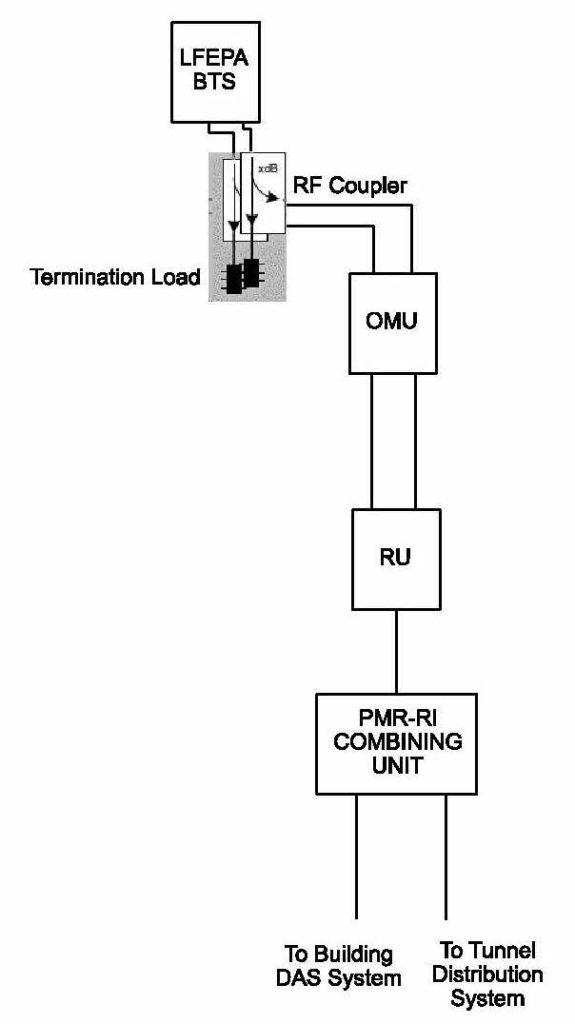
Figure 6. LFEPA System Schematic
Station Information and Security Systems (SISS)
The SISS systems provided for the Elizabeth Line are a similar offering for other metro style railways. The systems are described in more detail below and as they are mainly stations based, they generally report their status and have control from the SMS with a few exceptions.
CCTV
An IP based CCTV System is used in the Elizabeth Line (except for analytics cameras used in portal mouths and Plumstead Sidings) to provide real time video images, for the purposes of security, operations and public reassurance at stations, shafts, portals, traction power buildings, depot, sidings and external equipment rooms.
The main CCTV system consists of:
- CCTV Cameras
Full HD (1080p) IP based cameras have excellent low light performance and are powered by PoE/PoE+ through ethernet switches. Co-located cameras are connected to different CDN LAN switches, so that the loss of a switch does not result in the loss of all the camera images in an area, hence providing resilience.
- Network Video Recorders (NVR)
The video streams from the allocated cameras are recorded in NVRs at a continuous rate of 3fps rising to 25fps in “event” mode. Multiple NVRs are distributed across the COS to provide resilience and minimise bandwidth usage as the recording takes place at the edge of the network, local to the camera location.
- Video Management System (VMS)
The VMS is responsible for the assignment of cameras to recorders and handling of the playback and search functions. Operators are restricted by the assignment of privileges to which functions they can access, along with restricting access to cameras and monitors available on the system. A Station Operator is restricted to local cameras and monitors, whilst RCC Operators have access to all cameras and monitors across the COS at the RCC and Back-Up Control Facility (BUCF).
- CCTV Workstations
The access to CCTV live images and recorded footage is provided through integration with the CMS and SMS at each station. This is the primary means of access and provides:
-
- Access to live and recorded images from any camera at stations, shafts, portals, routeway sites, etc.
- Review recordings bookmarked as an event by the SMS/CMS
- View images in a single or split screen view, of up to 12 different cameras simultaneously
- Synchronised playback of images from different cameras in split screen viewing
- Rewind and fast forward video recordings in increment up to 32x speed
- Digital zoom on recorded images
- Review and accept alarms that have been generated within the VMS
- In the event of CMS or SMS failure, direct access to the VMS is obtained via local keyboard
- Portal Mouth Intruder Detection
Not strictly a SISS system but at the portal entrances an Intruder Detection system is provided to monitor tunnel portals and detect intruders and trespassers entering the tunnels. The Intruder Detection system consists of Laser Scan Detectors, CCTV Cameras and LED IR Light Sources. The laser scanner detects intruders entering the tunnel and switches the associated portal cameras allowing the operators at the RCC to view the intruder.
Detection of intrusion at each portal mouth is based on 2 laser scan detectors. Each detector monitoring 3 zones. Zone A1 monitoring the walkway, Zone B1 monitoring on track, Zone B2 monitoring a set height above B1. An alarm is not raised where an object is detected in both B1 and B2 as this indicates that a train has passed through the detection area. Refer to below Figure 5 for sensor zones.

Figure 7. Sensor zones
Public Address/ Voice Alarm System (PA/VA)
The PA/VA system in the COS stations provides live and pre-recorded messages for public and train-running information plus automatic alarm/emergency messages in the event of fire evacuation. The system comprises two racks located in station CERs containing amplification and routing equipment, speakers located throughout the station and field equipment such as microphones including platform radio microphones, RCC and SOR desk microphones, station intervention shaft fire microphone, SOR fire microphone, ambient noise sensors (ANS), and induction loops.
The system is integrated with the Station Management System (SMS) and Central Management System (CMS). This allows the operators at the SOR and RCC to control and monitor the PA/VA systems remotely.
Customer Information System (CIS)
The CIS provides train-running information to the public including next train arrival/departure time, information about any delays or disruptions and at which stations the trains will be stopping. The system comprises of Next Train Indicator (NTI) displays in platforms, Staff Information Displays (StID), Service Information Displays (SID), Electronic Service Update Board (ESUB), CIS Servers and PID Servers. Two PID servers (a hot standby pair) are located in the RCC and in each station and the information that needs to be displayed on the CIS screens are driven from these PID servers. The PID Servers also provide access to the status of the displays at each station to the CMS operators at the RCC and the SMS operators in the SORs. The operators at the RCC and SORs can also type freeform text messages to the station displays.
Driver Only Operated CCTV (DOO CCTV)
The DOO CCTV system provides the train driver a view of the platform to displays integrated to the train to assist the prevention of accidents, reducing the chance of passengers becoming trapped in the train doors or slipping down the gaps between the platform and the train. The system is designed to deliver images from platform to the train driver cab monitors via a modulated radio carrier signal, coupled through a radiating cable (Leaky Feeder) transmission cable and received by the train-borne equipment. The video signals from cameras are modulated onto low power RF carriers and fed into a radiating cable installed under the nosing of each platform. The train then receives these signals coupled via the antenna installed on the train. The RF signals are demodulated back to baseband video and displayed in the train driver’s cab monitor.
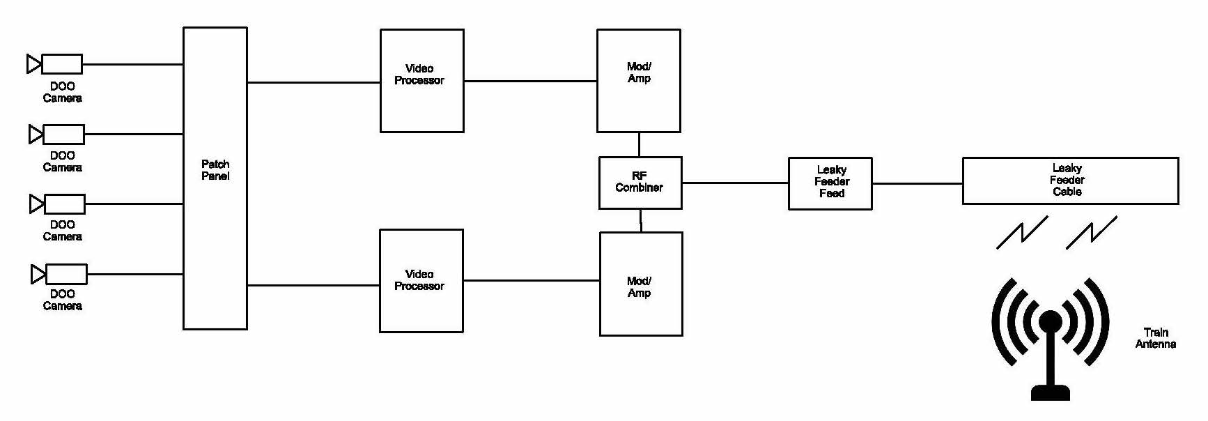
Figure 8. DOO CCTV System Schematic
The DOO System is divided into three parts:
- The Platform Imaging Sub-System
Cameras are installed at each platform to capture images of the Platform Train Interface (PTI). Analogue cameras are used due to low latency compared to IP cameras, an essential requirement for PTI safety. Images from the platform cameras are presented to the DOO cabinet for processing. A Retractable Mounting System (RMS) is used to install the cameras on the surface stations. This system accommodates up to two cameras on a retractable mounting arm which can be electrically lowered to a safe position for maintenance hence avoiding the need for possessions and isolations.
- The Platform Transmission Sub-System
The Video Modulator receives video signals from the camera feeds and modulates these onto a carrier signal. The output from the modulator is then passed to an RF combiner and radiating (leaky feeder) cable in the platform via feed coaxial cable. The radiating cable is mounted along the platform at a height that brings it into proximity to the train borne antennas as the train pulls into and out of the station.
- Train-borne DOO CCTV Sub-System Overview
The antennas installed on the train receive the RF video signals radiated from the cable mounted along the length of the platform and are connected to the train borne receivers. The receiver units demodulate the RF signals back to video signals and display the images on the in-cab monitors.
As a routeway system, the DOO CCTV system reports its health status into the CMS, providing checks on many of its component assets including power supplies, amplifiers, cabling, cameras images and is also monitored from the Class 345 Elizabeth Line rolling stock, which are the main ‘consumers’ of the images produced by the system.
Early Operating Experience
We are now at the stage of having installed and commissioned the majority of the Communications and Control systems for the Elizabeth Line and have now been operating them for a number of months. The immediate goal is to establish a stable enough set of systems which can support the entry into Trial Operations and then Revenue service in 2022 for the Central Operating Section. Naturally, the early weeks and months of operation have seen a number of failures, difficulties in systems and people operation and many lessons learned. This is to be expected for this stage of a new railway development and is part of achieving the goal of a reliable train service achieving 95% Passenger Performance Measure (PPM). The majority of the systems monitoring facilities are delivering operating data to the maintainers and asset managers, the longer term task now is to feed this into considered strategic asset interventions which maximise the effectiveness and efficiency of staff activities.
The Road Ahead
Once operating the COS reliably, the integration with the surface sections must take place to provide the full end to end 96km of Elizabeth Line route. The emphasis at this stage is likely to shift to innovation and improvement, looking to see where technology development, which never stands still, can bring further operating efficiencies and maintenance optimisation. Obvious candidates for inclusion are increasing use of wireless technologies to further automate tasks and increase the use of sensors and actuators for monitoring and system control. The further use of additional security and passenger facing technologies such as intelligent video analytics and passenger counting and measurement technologies will likely feature in a further rollout of technology. Within a short time horizon, it is probably likely that the use of Artificial Intelligence to drive better intervention outcomes and diagnosis of fault patterns will feature increasingly in the operation of railways globally and coupling this with the technology rich Elizabeth Line has massive potential to improve what should be by then, a UK and world leading railway performance.
Conclusion
The implementation of the chosen telecoms technologies on the Elizabeth Line has seen a step change in the use of detection technologies to help predict and prevent failures giving the Operator and Maintainer more ‘eyes and ears’ on the state of a UK railway than ever before. It is still early days in the operation of the line and the acquisition of the skills necessary to maximise efficiency and minimise railway downtime. As the reliability of the systems increases through Trial Running, Trial Operations and the early days of revenue service, personnel will acquire the necessary skills to ensure that the digital tools available provide the maximum advantage.
One of the challenges in the early days of operation has been to ensure that the information provided is understood well enough to allow timely and appropriate intervention to prevent failure. With much more information available than has been seen on existing railways, intelligent responses and deployment of staff for maximum benefit, is a set of skills in itself which have to be learned and acquired through experience and hard work. A comprehensive training programme and associated set of competencies for all technical staff has helped to put into place the appropriate skills necessary for diagnosing and responding to all types of status and health information.
To conclude then, has the implementation of the Elizabeth Line lived up to the original vision and delivered a technology rich infrastructure which provides optimised monitoring and control? The answer to that is probably a cautious ‘Yes’, acknowledging that there is still a way to go to develop to the required levels of system reliability and staff and process maturity for reliable train service. This is natural at this stage of a railway commissioning when the railway involved has this elevated level of complexity and technology deployment.
Abbreviations
Term Description
ALU Airwave London Underground
ANS Ambient Noise Sensor
BTS Base Transceiver Stations
ACRL Airwave Crossrail
BUCF Backup Control Facility
CCTV Closed Circuit Television
CDN Crossrail Data Network
CIS Customer Information System
COS Central Operating Section
CMS Central Management System
DAS Distributed Antenna System
DOO Driver Only Operated
ESUB Electronic Service Update Board
fps frames per second
GSM-R Global System for Mobile Communications – Railway
IP Internet Protocol
IR Infrared
LAN Local Area Network
LFEPA London Fire and Emergency Planning Authority
LU London Underground
MART Mean Active Repair Time
NVR Network Video Recorder
NTI Next Train Indicator
NR Network Rail
OMU Optical Master Unit
PA/VA Public Address/ Voice Alarm
PID Passenger Information Display
PMR-RI Private Mobile Radio – Radiating Infrastructure
PoE Power over Ethernet
PPM Passenger Performance Measure
PTI Platform Train Interface
RCC Route Control Centre
RCM Railcom Manager
RFLI Rail for London Infrastructure
RF Radio Frequency
RFoF Radio Frequency over Fibre
RMS Retractable Mounting System
RTU Remote Terminal Unit
RU Remote Unit
SCADA Supervisory Control and Data Acquisition
SISS Station Information and Security Systems
SOR Station Operations Room
SMS Station Management System
StID Staff Information Displays
TEC Telecom Engineering Centre
TETRA Terrestrial Trunk Radio
VMS Video Management System
VOIP Voice over Internet Protocol
-
Authors