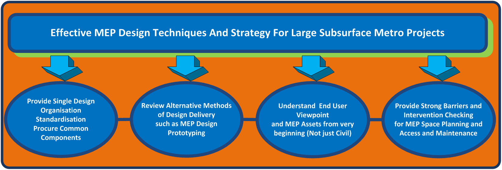
Effective MEP design techniques and strategy for large subsurface metro projects
Document
type: Technical Paper
Author:
Jonathan King FIET, ICE Publishing
Publication
Date: 30/09/2017
-
Read the full document
1. Optimum MEP Design Strategy and Common Components
1.1 Background
Mechanical, Electrical and Public Heath (MEP) design on large transport projects can be delivered in many different ways. The design strategy can be influenced from the projects procurement strategy which is based on selection and award mechanisms way beyond the focus of the final MEP offering to the RO (2). Large Railway projects are also burdened with a high level of political influence as mega projects are always on the political agenda. Therefore decisions can be made from a political perspective rather than from an Engineering one.
Large Subsurface Railway projects undertake very long programmes and early parts of construction tend to be pushed forward. It is widely acknowledged this is the case, especially for Tunnelling and Station contracts which need accelerating to achieve programme. This can impact the MEP quality for design and delivery, as decisions can be based on Civil Assets.
Performance, cost and time are the fundamental elements which make up the basis of most projects. Each element needs to be as balanced as much as practical to achieve a successful project (2). This can be seen below;
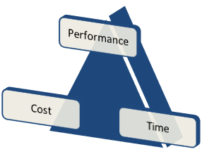
Figure 1: Time, Cost, and Performance Triangle
Having presented the three elements, cost is usually given high priority as guaranteeing the large funding is very difficult. Therefore by focusing on the finance it can allow projects to gain momentum and move forward in the early stages of development to secure act of parliament (3). However, that said, using commercial incentives and drivers through the delivery of the remainder of the programme can impact quality and final MEP offering to the RO.
MEP costs, complexity and emergence can be found later in a project due to procurement selection and contract incentives. Whichever the case when contracts are let contractors and suppliers are the main beneficiary of such items, and not the delivery organisation (DO) or indeed the RO. Therefore, MEP should be given focus and driven through the programme from the start. It has been quoted that Whole Life Costs (WLC), standardisation and commonality are moving up the agenda in mega projects and need to be in the future[1]. To allow a high quality final MEP product the MEP design delivery should be thought of in its entirety.
The Civil elements of large projects equate to more than the MEP Systems in terms of scale. This can be overwhelming and are thought about first, as the programme dictate, however they cannot be thought about in the same way as MEP. Civil elements do not have the same criteria needed for design and installation for the RO and don’t need the same frequency of operation and maintenance, as for MEP Systems. This is this main reason they are so different and must be thought about systematically for MEP design, procurement and delivery strategy.
1.2 Railway Operator Objectives
If we take a bottom up look into a MEP product offering in Figure 2, from the RO perspective it can point to aspects that are not readily thought about in the early stages of requirement planning, design and procurement in the DO. It is highlighted in the figure that the main theme emulating through is commonality, standardisation and quality for MEP design and procurement. These can critically help achieve the RO base objectives.
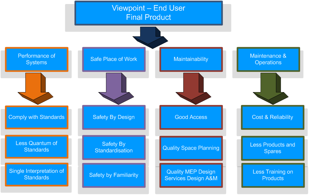
Figure 2: Infrastructure Manager Objectives and Route to Optimum Final MEP Product
When Infrastructure is handed over the RO needs to operate the systems, and the task of the DO is to provide a safe working environment for the RO to work. When infrastructure is designed and installed in a way that maintenance is hard to achieve, assets can be left unmaintained past their life expectancy. Failures can then occur, reducing performance of the Railway System. This type of scenario should be avoided as much as practical for projects involved in new design. Design also needs to comply with the Construction Design Management (CDM) regulations (4), where operations and especially maintenance and replacement is given much more focus in the latest revision of the regulations, from a design and delivery perspective. This puts more onerous on the DO to delivery such design.
1.3 MEP Design Model
The optimum MEP design model on a project to provide high MEP quality is arguably best placed with an SDO. This would be in one location to manage and develop the design at least a RIBA F (1)/Grip 6 (5), ideally before the engagement of MEP fit out contracts. The SDO make up could be a variety of different organisations, models and formats, but must be a singular group of Engineers whose objectives are the same.
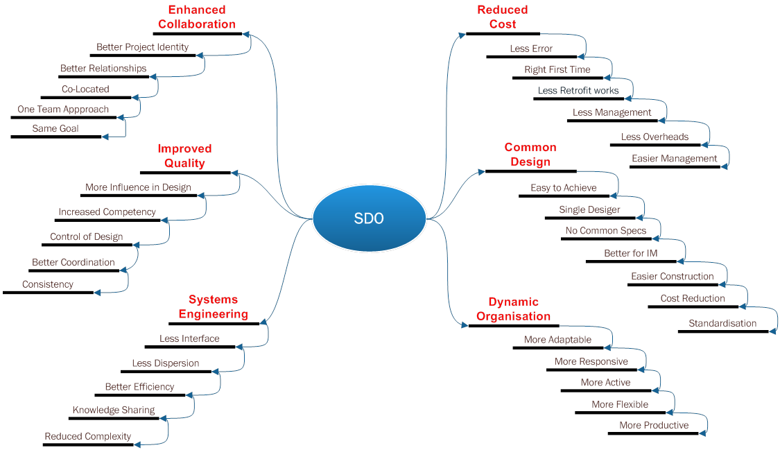
When construction contracts are let the influence of design change and quality is reduced. Designer’s incentives and mind set are usually to delivery best quality and endeavour to be collaborative with clients. However, a contractor’s incentive is usually the opposite and the driver is to achieve financial gain, thus restricting designers, especially when the programme is delayed. Therefore if a contractor slots in-between the designer and client this is arguably the less favourable position for a client and designer, and thus influence in design. Unfortunately nowadays this is usually the case in most contracts, but if there is a SDO then at least there will be better formed relationships to allow better quality to surface. Benefits of engaging a SDO model are shown in Figure 3.
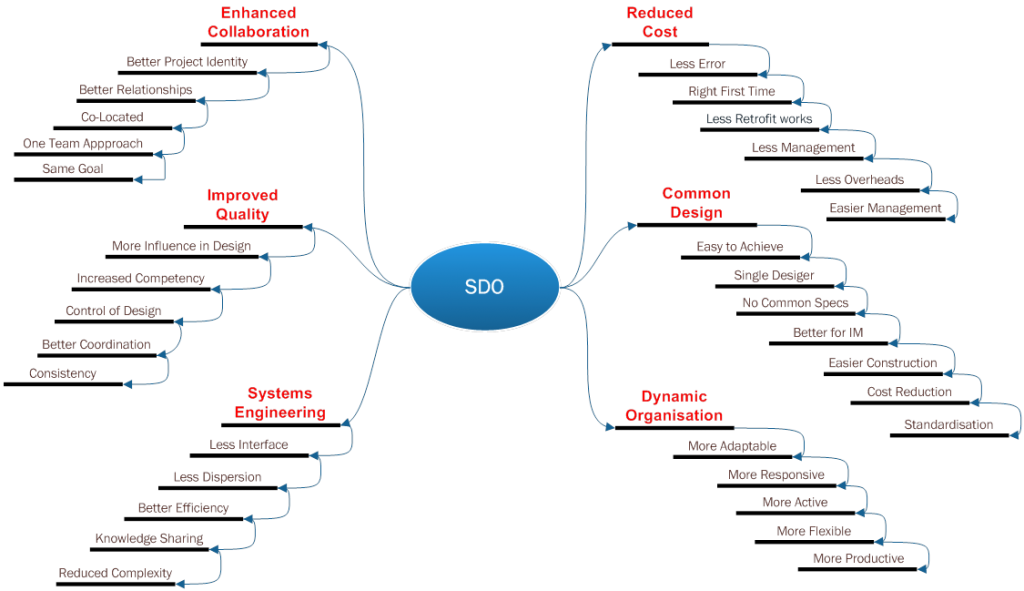
Figure 3: Preferred MEP Design Model with SDO
Recent UK major projects such as Jubilee Line Extension (JLE) (6) (7) and Chanel Tunnel (CTRL), Sections 1&2 were a SDO model. LU developed the JLE concept design who brought in consultants to assist and taken on by a single D&B contractor (7). CTRL concept design was undertaken by Rail Link Engineering (RLE) and taken on by a single D&B contractor. For a multiple route, the magnitude of different designers grow exponentially as projects evolve leading to designs becoming unmanageable and uncommon for the DO.
So, why should an SDO work better than a multiple design delivery?
- Enhanced Collaboration – physical proximity or co-locating design teams to work together allows quality and quantity of interactions. By working together for the same goal it brings about many advantages such as early decision making, project identity and project brand. Designers working in their own organisations are not as committed to a single project, where significant effort is constantly required to achieve milestones to keep up with programme on major projects. Communication is improved where much effort to go to meetings involving travelling distances are costly and time consuming. Working together in a real time environment creates a common understanding of the project.
- Improved Quality – will be improved due to the items mentioned above and will become better as teams are more efficient working together. When teams work together they can reach better consistency and coordination focusing on the same goal. Competency can be improved using knowledge sharing. Transparency of this aspect in organisations will be surfaced, and thus will be visible and can be improved where required. This is not the case when design teams are dispersed.
- Systems Engineering – less dispersion of staff and therefore interfaces easier to manage and control. System Engineering is coordination, integration and meeting of requirements. When there is better coordination between teams this aspect will naturally be improved. There can also be common engineering initiatives through knowledge sharing ideas to improve design efficiency and also document quantum. This can be especially with the Systems disciplines such as Reliability Availability Maintainability (RAM) modelling and Engineering Safety Management (ESM), Human Factors (HF) and Electromagnetic Compatibility (EMC). In a Multiple strategy each designer would prepare documents independently at each location, creating large amount of work and confusion. An SDO would produce generic ones and rolled out across the programme, reducing quantum and complexity for the DO.
- Reduced Cost – will be reduced due to design quality, less overheads and less middle management. If the quality is improved then there is less chance of error, rework and retrofit work. Less interface and formal meeting structures required resulting in quicker decision making. Using common design methods would improve efficiency and reduce work load, thus reducing cost. Efficient and tighter project controls would be provided, where physical proximity enhances management controls which allows management to effectively manage and lead, as it knows where and what everyone in the organisation is doing in the project.
- Common Design – will be automatically provided in a SDO, therefore not requiring common design initiatives. These add more effort and add complexity, confusion, cost and time. Common design improves efficiency, safety and standardisation.
- Dynamic Organisation – quicker to change and be much more dynamic to undertake changes reducing impacts on cost and programme. Technology changes such as recent advantages in LED lighting, statutory regulations such as the recent Eco Design Directive 2009, and CDM 2015 will be enforced. Changes required from final Railway Systems designs, such as final loads effecting power and HVAC requirements, i.e. Comms, Signalling and Tunnel Ventilation all impact MEP design.
Aspects from a SDO type model can be seen similar to aspects found in a procurement concept termed “Integrated Project Delivery” (IPD) (8). Adopting a more integrated approach to design and delivery such as a SDO will have similar benefits. The Macleamy curve illustrates an IPD approach (8). This shows the idea of making decisions early when using IPD where opportunity to influence positive outcomes is maximised and costs minimised, especially from the designer and client perspective. Curves showing the effort required to change design is shown along with the costs associated with the changes, and shows with an IPD application against a traditional approach.
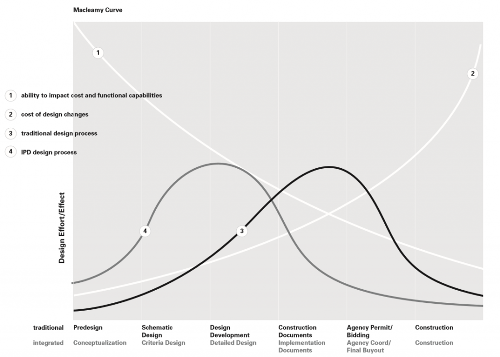
Figure 4: Macleamy curve showing IPD and traditional design
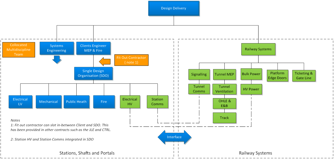
A typical organogram can be seen in Figure 5. SDO should be retained and engaged throughout E&F detailed design and on site to ensure retention of experience and responsibility. Station High Voltage (HV) and Station Communications (Comms) shown in the organogram is also included in the SDO as they are such a close interface with the stations infrastructure and best placed for coordination. It would be advantageous to provide a full BIM model to allow the fixing of costs and selection of the equipment for the fit out contractor. When the BIM model is provided this should be held on site. The 3D aspects of the BIM can allow the contractor to engage F design to J/K, and also providing the much needed construction A&M input to the 3D model on site. The MEP 3D model must be held on site with final changes and input from construction specialists alongside designers.
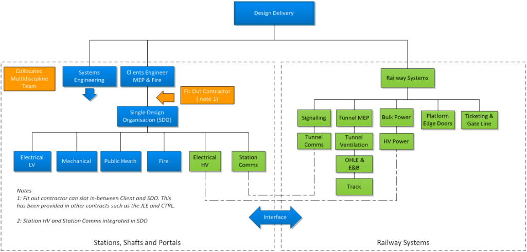
Figure 5: Organogram of Typical SDO Design Delivery Route
1.4 Common MEP Design
Common design is required on major subsurface projects for MEP systems to allow a better final product to hand over to the RO to maintain and replace over the life cycle. It is also much better for WLC purposes. Standardisation is an important aspect of MEP Engineering design and should be provided as much as practical to allow a much better end product (9). Common design is hard to infiltrate in the early parts of functional requirements, as its can be seen as a difficult requirement to formulate effectively.
Providing a common set of principles or specifications does not guarantee a common design. Multiple designers by their very nature will adopt and understand requirements and specifications very differently. Differences in the physical connections of the brain are at the root of what make people think and behave differently from one another (10). This is a scientific fact, and would be the same for multiple design Engineers, when interpreting requirements and standards on such projects.
The safest way to achieve a common design is to provide an SDO. To ensure a complete common design in all respects without compromise is to use a single designer per discipline. This can be seen in Figure 6;

Figure 6: IDEFO Diagram for MEP Common Design
1.5 Common MEP Products
The common design theme can also extend to the actual final MEP product usually selected by the MEP contractor. The main MEP products used in a project which has the same RO should effectively be the same where possible, i.e. standardised (9). Where multiple contractors are undertaking the MEP fit out then this is difficult to achieve, as they select their preferred equipment supplier due to cost and preferred business relationship. When this is the case a framework supplier approach can overcome the common component issues and can be specified by the DO. If a single MEP contractor is appointed for all the multiple station MEP works they are likely to procure from the same supplier due to cost, therefore the common component aspect can be fulfilled, using this method.
Common product selection doesn’t have to be for every piece of equipment, only items which effect operations and maintenance. This also has a safety feature where the same item of plant is expected to be the same in all site locations. Training and understanding of the same plant will be simpler, therefore should be safer in operation. Depending on the scale of the infrastructure project suppliers may not be able to supply the project due to company constraints and limits. If this is the case then a small number of suppliers of the same equipment maybe sort. In terms of scale, a rough guide would be 15 large underground stations could be considered a limit, based on items such as LV Switchgear and UPS. New projects such as Crossrail for example should be able to handle a single supplier for the majority of MEP plant and components. Whereas projects such as Riyadh metro (11) maybe too big for single source suppliers of equipment. A typical set of common components can be seen in Figure 7.
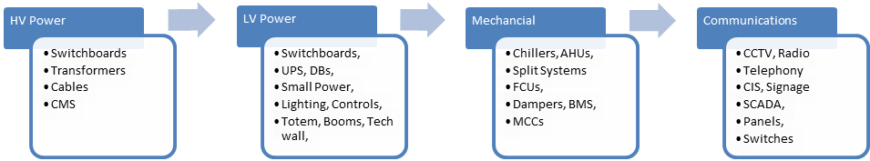
Figure 7: Common MEP Component Selection Equipment
Traditionally the fit out contractor selects equipment as liabilities remain with the contractor. However, these don’t tend to be realised with government due to publicity. If a client selects equipment then they could be made liable which can be seen as risk or exposure. Table 1 summarises both strengths and weaknesses for multiple and single design and component selection.
Table 1: Multiple and Single Designer and Component Selection
Model Type
Aspect
Multiple Designer Multiple Product Selection SDO Designer Single Component Selection Strength Spread Risk
Spread Cost
Wider Economic Gain
Loosely Coupled ORG[2]
Spread Risk
Enhanced Interface & Coordination
Reduced Cost & Retrofit
Common Design
Improves Project Identity, Collaboration, Quality and Project Control
Less Spares
Less Training
Safer
Competitive
More Reliable
Improved WLC
Reduced Complexity
Better Maintenance
Weakness Multiple Designs
Multiple Products
Larger Interfaces
More Design Corrections
Less Control
Bigger Management
Higher Overheads
More Spares
More Training
Less Safe
Less Reliable
Tightly Coupled ORG2 Monopoly
Tightly Coupled ORG 2
Liability
2 Prototyping MEP Design
2.1 Background
Prototyping is not a new technique but it is not normally associated with MEP design as a product. This would be quite novel. It can be considered in a programme to help MEP design to test and achieve its requirements. This can be provided where very large infrastructure projects have multiple similar items. A prime example is Sub-surface Railway projects, where SSP are very similar. Crossrail is a good example and other projects such as Riyadh (11). Templates are more used for Civil space planning in concept design but not so much in final MEP Systems or Layouts.
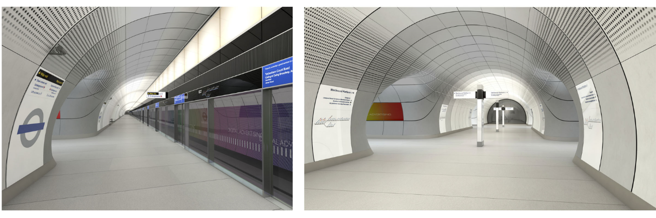
Prototyping a whole MEP installation in a station for subsurface stations is unrealistic, compared to small elements of manufactured equipment which are normally prototyped. Prototyping is mainly for its constructability, maintainability, appearance, functionality and compliance. The usual items for subsurface stations are; Platforms, Technology Walls, Lighting Booms, Platform Edge Doors (PED) and Totems. These are unique elements to projects themselves, and some of these items can be seen in Figure 8. Most standard MEP products are not prototyped, however samples are provided to the client and visits to manufactures premises to view products are conducted to view quality of production.

Figure 8: Platforms, Technology Wall and Totems
2.2 MEP Design Prototyping Method
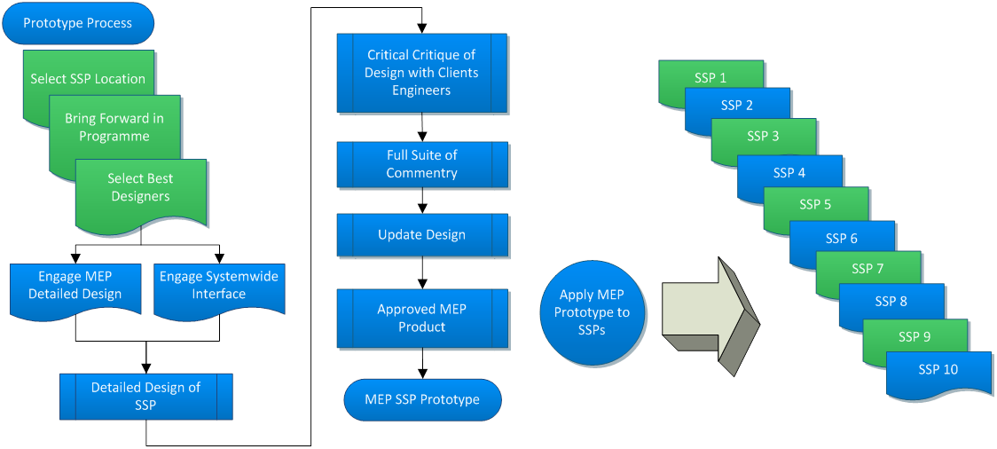
The method that can be provided is relatively simple. Bring forward part of the programme such as an SSP. These are the main typical infrastructure items where multiple items occur that can be tested in MEP design.
Undertake a design of a single location with Civil, Architecture, Structure and MEP along with Railway Systems Input where required. The other disciplines will be needed to allow the full integration and testing of design for the full complement of MEP services. The design can also be used as the real design when the specific site is required to be provided in a contract. It can also be brought up to date if the time lag is very long before its implementation. The process can be seen in Figure 9.

Figure 9: MEP Design Prototype Process
With design provided the completed design product can be tested with all the interfacing parties, Railway Systems, RO, Access and maintenance and Clients Engineering teams to test requirements. Systems Engineering EMC, RAMS can also be applied. From this test all the comments and reviews can be implemented into the final MEP design product at this location.
When the final product is designed and has achieved quality, compliance and meets the requirements it can be used as a prototype MEP design model at other locations. This can then almost replicate the product and fit as much as practical as a template. Designers use the design and make fit to the new location geometry. Obviously the different locations will have different geometry and arrangements. However these should be minor and the design should be very similar. The process is quite unusual and is more in line with manufacturers and their products but essentially this is what an SSP is, a product. If a SSP can be viewed as a product then the idea of design prototyping should be strongly looked at in subsurface railway projects, where multiple sites of the same product are provided.
3 MEP Space Planning, Service Routing and Access and Maintenance
3.1 Background
MEP space planning is a critical and complex element of design work at the start of Railway projects and further into the project lifecycle. There are guides in the market place which aid the MEP designer to apply good practice who also use their knowledge and experience. The guides tend to be from other industries but common MEP principles can be used from industry to industry to good measure.
Railways are unique to other industry and extra understanding needs to be applied due to the complexity of interfaces involved, mix of standards used and differing RO requirements. RO do have good standards to follow but are very limited in this respect and some RO standards force the designers into even more bespoke infrastructure requirements from existing and even emerging standards. A&M is coming into much more focus by the RO as their operations and availability of systems are increasing all the time i.e. the 24hr tube service.
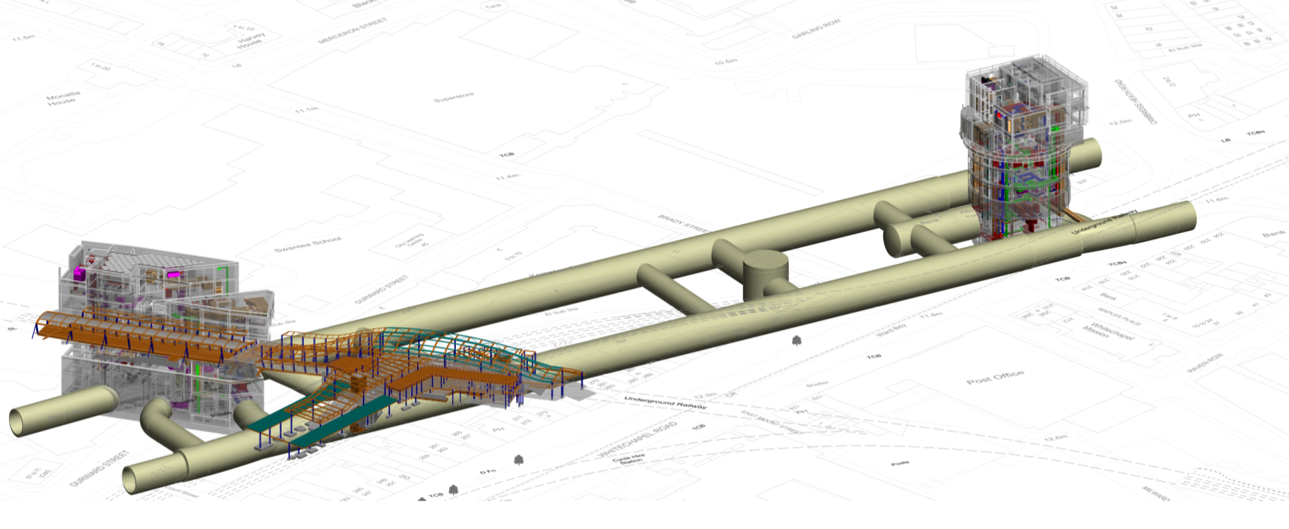
Coordination with other Engineering disciplines such as civil, structural and architectural are also challenging. Typical structures can be seen in Figure 10, and makes MEP space planning and service routing very complex and hard to get right first time. The challenge is even more so when the final information on equipment is not always known and Railway Systemwide design is usually later in the programme. Allowing for the optimum space is difficult to achieve as so many variables exist. Excessive space is seen as wastage and too little space puts pressure on the RO and contractor to work with the space left and compromise is usually sort. Assumptions are usually provided and need to be verified by the Clients Engineers throughout design.

Figure 10: Whitechapel Station Illustrates complex geometry and coordination
3.2 Guidance
Guidance can be used from many sources. Experience and competence based on previous projects where successful implementation has been provided to the RO is probably key. This includes A&M that has been proven by maintaining plant safely. Typical guides in the market place used by designers are the following;
- BSRIA TN 15/2001 Rules of Thumb Assessing Building Services(12)
- BSRIA BG 9/2011 Rules of Thumb Guidelines for Building Services(13)
- BSRIA BG 55/2014 Safety in Building Services design(14)
- MOD Design & Maintenance Guide 08 Space requirements for plant access, operation and maintenance 08(15).
- CIBSE Maintenance engineering and management CIBSE Guide M(9)
- CIBSE Electricity in Buildings CIBSE Guide K (16)
The MOD guide is particularly well detailed offering many plant applications. This is now recited in the building regulations and is endorsed by CIBSE. Designers should already be using these and others to endeavour to provide a good quality design. These can be enforced to guide the designers to provide a suitable design offering.
3.3 Delivery Measures
It is very difficult to set efficient space planning, good quality service route design and good access and maintenance within project functional requirements. Therefore additional methods need to be put in place to protect the DO and end user from issues arising these aspects of design and which hold such a critical place in the design development. A typical IDEFO illustrates the control measures and mechanism for optimum MEP design in Figure 11.
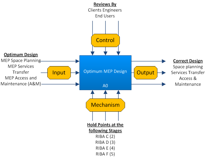
Figure 11: IDEFO MEP Design Control Measures
To ensure suitable space planning and service routing is achieved, intervention points can be put in place with certain criteria along the delivery route of design. The criteria can be a design template check. These create barriers of protection for the DO who then can ensure the quality of these items are guaranteed at the end of the project life cycle. The construction Engineers can also be involved during the later stages. This can be seen in Figure 12
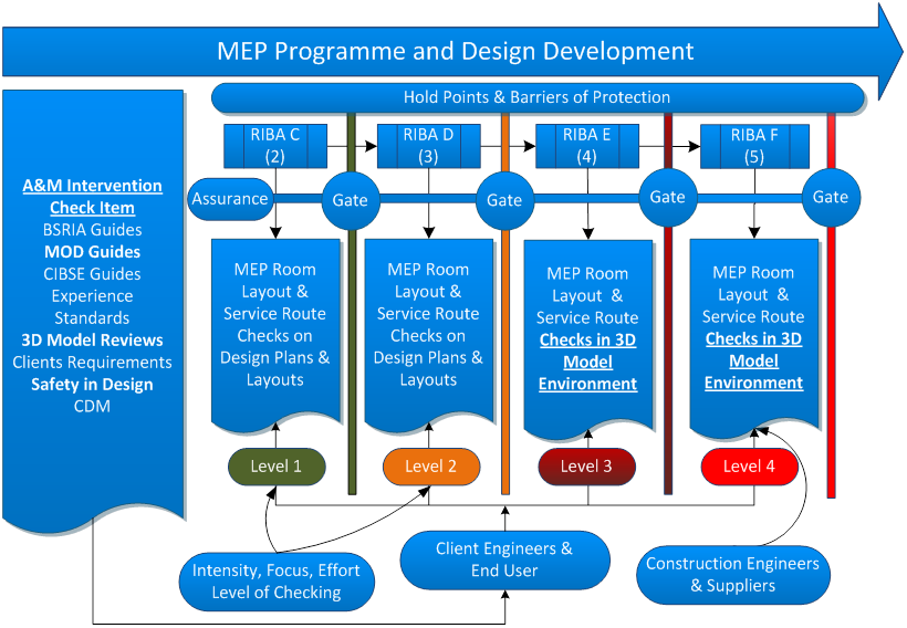
Figure 12: Design Checking For MEP Space Planning, Service Routing and A&M
4 Summary
To set optimum MEP design strategies in subsurface railway projects the DO is recommended to engage in initial review of how the MEP product will be finally received by the RO. The ROs objectives are unique and are not focused on time or cost which is at the top of the agenda at beginnings of major programmes. The DO should take a look from an RO viewpoint as it can be can be quite a different picture, and the picture needs to be known when making decisions on project procurement and MEP design strategy.
MEP assets are vastly different to Civil and Structural assets in terms of A&M and operations so they need to be viewed differently in terms of design strategy and even more so in product selection and design delivery. Traditionally large Railway subsurface projects are led by Civil disciplines and mind sets as major Civil decisions need to be made earlier in the programme. These decisions can have heavy MEP impacts to the project which can lay hidden and until later in the project when MEP and Systems fit out has more focus, which of course can be too late.
The SDO method of design delivery has a range advantages from all aspects of the project. This approach can be an encouraging design delivery route which can not only reduce cost but can vastly improve quality, and surprisingly programme. Many advantages can be seen similar to that of an IPD approach which are known about in other industry. Collaboration being the most prominent alongside common design. Common design principles should be provided to allow standardisation in design. This theme should be extend to the MEP component selection. This will offer improved maintenance policy and operations procedures and finally WLC for the RO.
Alternative design strategy and templates should be researched such as design prototyping. This method can also overcome the challenges of providing route to optimum MEP design. The concept is not easy to grasp, as it’s not a build prototype but design only. However, it makes sense for design of multiple units of the same type. The main advantages are the same as normal advantages brought about by prototyping. Costs are very little to change one design, rather than 10s of numbers of designs late in the programme. Only by undertaking a full design to a very detailed level where all design and interface related issues will be truly tested and uncovered.
The design for MEP space planning, services transfer and Access and Maintenance is a long and complex undertaking. For the DO it is hard to measure and not usually easily found in project functional requirements. Perhaps stronger statements are needed in such documents at early stages to refocus the issue. The challenge is for the designer to deliver a quality undertaking and for the DO to offer design guidance and perform measures to assess quality and compliance. The measures proposed are one of a more direct approach at each stage, in which intrusive reviews and interventions are necessary. This is using guidance from industry, experience, best practice, and assumptions. The client’s engineers and RO input is necessary at each stage. Finally, intensive detailed 3D review checking is critical through RIBA E and F1 & F2 stages.
In Summary, to overcome the MEP challenges for large subsurface Railway projects the methods and techniques described in this paper should be considered and adopted. Other routes selected can be achieved using multiple design strategy and procurement; however, this paper argues that there is a much better alternative to achieving the same outcome. This method also highlights the many advantages such as more manageable, more accurate, more cost effective and less challenging overall for the DO. It also recognised that a multiple approach is arguably less risk to the project as a whole, however this could be argued this is for construction rather than design. The DO and the RO will have most gain where advantages using a common design route and standardised product installation for maintenance practice and WLC are realised.
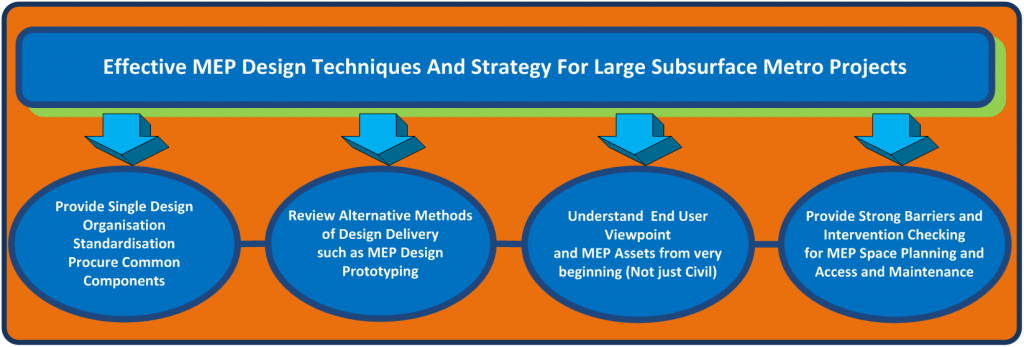
In summary the below should be followed for large subsurface metro projects;
5 Acknowledgements
Thanks goes to Rhys Williams (Crossrail) and Peter Toseland (Costain) for support and guidance on different elements in the technical paper.
6 References
- A Design Framework For Building Services BG 6/2104 . BISRA . 4th Edittion , s.l. : BISRIA, 2014.
- Standards, British. Construction procurement policies, strategies and procedures – Code of practice. s.l. : British Standards , 2011. BS 8534.
- www.parliament.uk. www.parliament.uk. [Online] http://www.parliament.uk/about/how/laws/bills/hybrid/.
- CDM Regulations. Statutory Instrument, Law, European and British. s.l. : British Standards, 2015, Construction Design Regulations. 51.
- The Guide To Investment Projects – Policy Manual . Network Rail . 2006.
- Tosland, Peter. Interview with Peter Tosland MEP Project Manager on Jubilee line . 23 September 2016.
- Michell, Bob. Jubilee Line Extension Concept to Completion . s.l. : Thomas Telford , 2003.
- Integrated Project Delivery : A Guide. AIA American Instutution of Architects . 2007.
- CIBSE Guide M Maintenance Engineering and Management . CIBSE. 2008.
- Liu, Dr. Hesheng. https://www.sciencedaily.com/releases. Science Daily . [Online] https://www.sciencedaily.com/releases/2013/02/130206131048.htm.
- Railway Technology . [Online] Railway Technology . http://www.railway-technology.com/projects/-riyadh-metro-saudi-arabia/.
- BSRIA. BSRIA TN 15/2001 Rules of Thumb for Assessing Building Services. 2001.
- —. BSRIA BG 9/2011 Rules of Thumb Guidelines for Building Services.
- —. BSRIA BG 55/2014 Safety in Building Services design.
- Space Requirements for Plant and Access, Operation and Maintenance . Ministry of Defence . 1996.
- CIBSE. CIBSE Electricity in Buildings CIBSE Guide K .
- Michael J. Papa, Tom D. Daniels, Barry K. Spiker. Organizational Communication: Perspectives and Trends.
- BSRIA Technical Note TN 10/92 Space Allowances For Building Services Distrubution Systems – Detail Design Stage. BSRIA. 1992.
[1] Quote taken from Professor Peter Hansford UCL at the next Generation of UK Mega Project Seminar September 2016
[2] A loosely coupled Organisation (ORG) is where any failure of part of the organisation could be absorbed more easily, whereas a tightly coupled organisation failure would be more catastrophic.
-
Authors

Jonathan King FIET - Crossrail Ltd
Jonathan has been working on the Crossrail project from 2006, firstly as a Crossrail supplier MDC, and FDC and more recently for Crossrail as an Engineering Manager and Engineering Safety Manager. Jonathan’s responsibility has mainly covered systems design, delivery, construction, and safety engineering aspects.
Jonathan has been in the Railway Industry for nearly two decades, working on projects such as CTRL section 2, Thames Link and SSL 4LM. Jonathan is also undertaking research on the Crossrail project under a programme affiliated with the University of Birmingham (UOB) for Reliability, Availability, and Safety (RAMS) and Integration.